EP1125660B1 - Schneidplatte - Google Patents
Schneidplatte Download PDFInfo
- Publication number
- EP1125660B1 EP1125660B1 EP01101033A EP01101033A EP1125660B1 EP 1125660 B1 EP1125660 B1 EP 1125660B1 EP 01101033 A EP01101033 A EP 01101033A EP 01101033 A EP01101033 A EP 01101033A EP 1125660 B1 EP1125660 B1 EP 1125660B1
- Authority
- EP
- European Patent Office
- Prior art keywords
- cutting plate
- reversible
- cutting
- plate according
- cutting edge
- Prior art date
- Legal status (The legal status is an assumption and is not a legal conclusion. Google has not performed a legal analysis and makes no representation as to the accuracy of the status listed.)
- Expired - Lifetime
Links
- 230000002441 reversible effect Effects 0.000 claims abstract description 27
- 239000000463 material Substances 0.000 claims abstract description 7
- 238000003754 machining Methods 0.000 claims abstract description 5
- 229910010293 ceramic material Inorganic materials 0.000 claims abstract description 3
- 210000000078 claw Anatomy 0.000 claims description 5
- 239000000919 ceramic Substances 0.000 description 2
- 229910001018 Cast iron Inorganic materials 0.000 description 1
- 238000005299 abrasion Methods 0.000 description 1
- 238000005266 casting Methods 0.000 description 1
- 229910052574 oxide ceramic Inorganic materials 0.000 description 1
- TWNQGVIAIRXVLR-UHFFFAOYSA-N oxo(oxoalumanyloxy)alumane Chemical compound O=[Al]O[Al]=O TWNQGVIAIRXVLR-UHFFFAOYSA-N 0.000 description 1
- RVTZCBVAJQQJTK-UHFFFAOYSA-N oxygen(2-);zirconium(4+) Chemical compound [O-2].[O-2].[Zr+4] RVTZCBVAJQQJTK-UHFFFAOYSA-N 0.000 description 1
- 229910001928 zirconium oxide Inorganic materials 0.000 description 1
Images

Classifications
-
- B—PERFORMING OPERATIONS; TRANSPORTING
- B23—MACHINE TOOLS; METAL-WORKING NOT OTHERWISE PROVIDED FOR
- B23B—TURNING; BORING
- B23B27/00—Tools for turning or boring machines; Tools of a similar kind in general; Accessories therefor
- B23B27/14—Cutting tools of which the bits or tips or cutting inserts are of special material
- B23B27/16—Cutting tools of which the bits or tips or cutting inserts are of special material with exchangeable cutting bits or cutting inserts, e.g. able to be clamped
- B23B27/1644—Cutting tools of which the bits or tips or cutting inserts are of special material with exchangeable cutting bits or cutting inserts, e.g. able to be clamped with plate-like cutting inserts of special shape clamped by a clamping member acting almost perpendicularly on the chip-forming plane and at the same time upon the wall of a hole in the cutting insert
- B23B27/1651—Cutting tools of which the bits or tips or cutting inserts are of special material with exchangeable cutting bits or cutting inserts, e.g. able to be clamped with plate-like cutting inserts of special shape clamped by a clamping member acting almost perpendicularly on the chip-forming plane and at the same time upon the wall of a hole in the cutting insert characterised by having a special shape
-
- B—PERFORMING OPERATIONS; TRANSPORTING
- B23—MACHINE TOOLS; METAL-WORKING NOT OTHERWISE PROVIDED FOR
- B23B—TURNING; BORING
- B23B2200/00—Details of cutting inserts
- B23B2200/08—Rake or top surfaces
- B23B2200/086—Rake or top surfaces with one or more grooves
- B23B2200/087—Rake or top surfaces with one or more grooves for chip breaking
-
- B—PERFORMING OPERATIONS; TRANSPORTING
- B23—MACHINE TOOLS; METAL-WORKING NOT OTHERWISE PROVIDED FOR
- B23B—TURNING; BORING
- B23B2200/00—Details of cutting inserts
- B23B2200/08—Rake or top surfaces
- B23B2200/086—Rake or top surfaces with one or more grooves
- B23B2200/088—Rake or top surfaces with one or more grooves for clamping
-
- Y—GENERAL TAGGING OF NEW TECHNOLOGICAL DEVELOPMENTS; GENERAL TAGGING OF CROSS-SECTIONAL TECHNOLOGIES SPANNING OVER SEVERAL SECTIONS OF THE IPC; TECHNICAL SUBJECTS COVERED BY FORMER USPC CROSS-REFERENCE ART COLLECTIONS [XRACs] AND DIGESTS
- Y10—TECHNICAL SUBJECTS COVERED BY FORMER USPC
- Y10T—TECHNICAL SUBJECTS COVERED BY FORMER US CLASSIFICATION
- Y10T407/00—Cutters, for shaping
- Y10T407/23—Cutters, for shaping including tool having plural alternatively usable cutting edges
- Y10T407/235—Cutters, for shaping including tool having plural alternatively usable cutting edges with integral chip breaker, guide or deflector
-
- Y—GENERAL TAGGING OF NEW TECHNOLOGICAL DEVELOPMENTS; GENERAL TAGGING OF CROSS-SECTIONAL TECHNOLOGIES SPANNING OVER SEVERAL SECTIONS OF THE IPC; TECHNICAL SUBJECTS COVERED BY FORMER USPC CROSS-REFERENCE ART COLLECTIONS [XRACs] AND DIGESTS
- Y10—TECHNICAL SUBJECTS COVERED BY FORMER USPC
- Y10T—TECHNICAL SUBJECTS COVERED BY FORMER US CLASSIFICATION
- Y10T407/00—Cutters, for shaping
- Y10T407/24—Cutters, for shaping with chip breaker, guide or deflector
- Y10T407/245—Cutters, for shaping with chip breaker, guide or deflector comprising concave surface in cutting face of tool
-
- Y—GENERAL TAGGING OF NEW TECHNOLOGICAL DEVELOPMENTS; GENERAL TAGGING OF CROSS-SECTIONAL TECHNOLOGIES SPANNING OVER SEVERAL SECTIONS OF THE IPC; TECHNICAL SUBJECTS COVERED BY FORMER USPC CROSS-REFERENCE ART COLLECTIONS [XRACs] AND DIGESTS
- Y10—TECHNICAL SUBJECTS COVERED BY FORMER USPC
- Y10T—TECHNICAL SUBJECTS COVERED BY FORMER US CLASSIFICATION
- Y10T407/00—Cutters, for shaping
- Y10T407/27—Cutters, for shaping comprising tool of specific chemical composition
Definitions
- the invention relates to an indexable insert made of ceramic for clamping in a cutting tool for machining cast materials according to the preamble of claim 1.
- a ceramic insert for clamping in a cutting tool for machining cast materials, in particular cast iron is known.
- the cutting plate includes on its upper side a star-shaped trough with four teeth for engagement of a clamping claw or a clamping finger of the cutting tool, wherein each corner of the insert has a minor cutting edge and a main cutting edge.
- the cutting tool consists of a clamping holder and a replaceable insert to be inserted into the clamping holder.
- the cutting plate is the part that engages the workpiece and this machined.
- the cutting plate must therefore be made of extremely hard material, which has the lowest possible abrasion when machining metallic workpieces.
- oxide-ceramic materials such as aluminum oxide or zirconium oxide. Such ceramic materials have a very high hardness and compressive strength, but only a limited tensile strength.
- the invention has for its object to improve an indexable insert according to the preamble of claim 1 so that the cast chips are removed from the cutting edge and thereby the cutting edge is relieved.
- this object is achieved in that the corners are ground in about 1 ⁇ 4 of the diagonal plane, pressed or injected and so on Form triangular surface or chip forming step and the triangular surface has at least one inclination.
- the castings are removed from the cutting edge corner to the center of the insert and thereby relieve the cutting edge. It is created by these measures a positive chip forming stage.
- the triangular surface is inclined by the secondary cutting edge in the direction of the side center at an angle ⁇ .
- An alternative embodiment is characterized in that the triangular surface is divided by the diagonal into two partial surfaces and at least one partial surface of the main cutting edge or the minor cutting edge is inclined at right angles through an angle ⁇ to the symmetry center.
- both partial surfaces are inclined towards the center of symmetry.
- Symmetry center is understood as the intersection of the diagonals of the cutting plate with the hypotenuse of the triangular surface.
- the angle ⁇ is preferably between 3 and 12 °. With a plate thickness d of 5 mm, z. B. a preferred maximum reduction x of 1.5 mm.
- the secondary cutting edges are preferably provided at their outer edge with a flat bearing surface which relieves the main cutting edge located on the other side when turning the cutting plate.
- the cutting plate is formed as an indexable insert, wherein the minor cutting edges and main cutting edges are arranged offset on both sides by 90 °, so that a main cutting edge on one side of a secondary cutting edge on the other side and vice versa , The main cutting edge is thus supported on the other side by the planar contact surface along the minor cutting edge.
- the planar contact surface preferably extends over the entire length of the minor cutting edge and has a width of preferably 1 mm.
- Each corner is divided into two triangles by the corresponding diagonal.
- the main cutting edge When viewed topically on an upper side, the main cutting edge is arranged in the clockwise direction in front of the diagonal and the secondary cutting edge is arranged behind the diagonal. This applies to clockwise cutting inserts. For left-hand cutting inserts this is the reverse case.
- the cutting plate For attachment of the cutting plate in the cutting tool, the cutting plate in a preferred embodiment, a star-shaped trough with four teeth, wherein the tines are each aligned with the center of a longitudinal side. In the trough engages a clamping finger of a clamping claw of the cutting tool so that it is fixed in position.
- all four corners of an upper side of the cutting plate can be used for cutting.
- an identical trough is arranged, so that a total of eight corners are available for cutting.
- a hole for engagement of a clamping bolt of the cutting tool in the cutting plate is arranged instead of the trough.
- the indexable insert can also have a smooth surface except the inventively formed corners. These inserts are also referred to as smooth inserts.
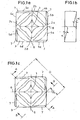
- FIG. 1a shows a side of an indexable insert with a star-shaped depression 1 with four points 2a, 2b, 2c, 2d which are each aligned with the middle 6 of a longitudinal side.
- the trough 1 is shaped such that a clamping finger of a clamping claw of a cutting tool fixes the indexable insert in exciting contact in the cutting tool (see FIG. 4).
- the corners of the indexable insert are respectively ground or pressed and form a chip forming step in the form and shape of a triangular surface 3.
- the main cutting edges are denoted by the reference numerals 4a, 4b, 4c, 4d and the minor cutting edges by the reference numerals 5a, 5b, 5c, 5d. It is assumed here by a clockwise plate.
- the chip forming step or triangular surface 3 extends approximately 1 ⁇ 4 of the length of the diagonal D of the cutting insert into the plate (see FIG. 1c).
- the chip forming stage 3 forms a triangular surface which slopes from the secondary cutting edge 5a, 5b, 5c, 5d in the direction of the center of the side 6 at an angle ⁇ .
- This angle ⁇ is between 3 and 12 °, preferably between 8 and 12 °. In this particular case, the angle ⁇ is 11 ° (see also Fig. 3).
- Fig. 1c shows the indexable insert of FIG. 1a from the bottom.
- the secondary cutting edges 5a, 5b, 5c, 5d and main cutting edges 4a, 4b, 4c, 4d are each offset by 90 ° on the two sides of the indexable insert so that a main cutting edge 4a , 4b, 4c, 4d on the one side a secondary cutting edge 5a, 5b, 5c, 5d on the other side opposite.
- the minor cutting edges 5a, 5b, 5c, 5d are provided at their outer edge with a flat bearing surface 7, which is the main cutting edge 4a, 4b, 4c, 4d located on the other side of the cutting insert relieved.
- Figure 2 shows a section along the line A - A in Fig. 1c.
- Fig. 4 shows the view of a clamping holder with a clamping claw 8, which fixes an indexable insert 9 according to the invention exciting.
- the clamping angle in this embodiment is -8 ° and the inclination angle is -7 °.
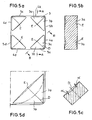
- FIG. 5a-d show an indexable insert according to the invention, in which the triangular surface 3 is divided by the diagonal D into two partial surfaces 3a, 3b.
- the two partial surfaces of the main cutting edge (4a, 4b, 4c, 4d) and the secondary cutting edge (5a, 5b, 5c, 5d) are inclined at right angles by an angle ⁇ to the center of symmetry E.
- Fig. 5d shows a corner of the cutting plate enlarged.
- 5b shows a section along the line AA of FIG. 5a
- FIG. 5c shows a section along the line BB of FIG. 5a.
- the angle ⁇ of the two slopes is in this case at 3 °. However, other angles can be used, if this ensures sufficient chip removal.
Landscapes
- Engineering & Computer Science (AREA)
- Mechanical Engineering (AREA)
- Cutting Tools, Boring Holders, And Turrets (AREA)
- Polishing Bodies And Polishing Tools (AREA)
- Processing Of Stones Or Stones Resemblance Materials (AREA)
- Milling Processes (AREA)
Description
- Die Erfindung betrifft eine Wendeschneidplatte aus Keramik zum Einspannen in ein Schneidwerkzeug zum Zerspanen von Gußwerkstoffen nach dem Oberbegriff des Anspruchs 1.
- Aus der EP 0 075 177 ist eine Wendeschneidplatte aus Keramik zum Einspannen in ein Schneidwerkzeug zum Zerspanen von Gußwerkstoffen, insbesondere Gußeisen, bekannt. Die Schneidplatte enthält auf ihrer Oberseite eine sternförmige Mulde mit vier Zacken zum Eingriff einer Spannpratze bzw. eines Klemmfingers des Schneidwerkzeugs, wobei jede Ecke der Wendeschneidplatte eine Nebenschneide und eine Hauptschneide aufweist.
- Das Schneidwerkzeug besteht demnach aus einem Klemmhalter und einer in den Klemmhalter einzusetzenden auswechselbaren Schneidplatte. Die Schneidplatte ist dasjenige Teil, das an dem Werkstück angreift und dieses spanend bearbeitet. Die Schneidplatte muß daher aus extrem hartem Material bestehen, das bei der Bearbeitung metallischer Werkstücke einen möglichst geringen Abrieb hat.
- Werkstoffe, die diesen Anforderungen genügen, sind oxidkeramische Werkstoffe, wie beispielsweise Aluminium-Oxid oder Zirkon-Oxid. Solche keramischen Werkstoffe haben eine sehr hohe Härte und Druckfestigkeit, jedoch eine nur begrenzte Zugfestigkeit.
- Der Erfindung liegt die Aufgabe zugrunde, eine Wendeschneidplatte nach dem Oberbegriff des Anspruchs 1 so zu verbessern, dass die Gußspäne von der Schneidkante abgeführt werden und dadurch die Schneidkante entlastet wird.
- Erfindungsgemäß wird diese Aufgabe dadurch gelöst, dass die Ecken in ca. ¼ der diagonalen Ebene eingeschliffen, eingepresst oder eingespritzt sind und so eine Dreiecksfläche bzw. Spanformstufe bilden und die Dreiecksfläche zumindest eine Neigung aufweist. Hierdurch werden die Gußspäne von der Schneidkantenecke zur Mitte der Schneidplatte hin abgeführt und entlasten dadurch die Schneidkante. Es wird durch diese Maßnahmen eine positive Spanformstufe geschaffen.
- In einer bevorzugten Ausführungsform ist die Dreiecksfläche von der Nebenschneide in Richtung Seitenmitte mit einem Winkel α geneigt.
- Eine alternative Ausführungsform ist dadurch gekennzeichnet, dass die Dreiecksfläche von der Diagonalen in zwei Teilflächen geteilt ist und zumindest eine Teilfläche von der Hauptschneide bzw. der Nebenschneide rechtwinklig um einen Winkel α zur Symmetriemitte hin geneigt ist. Vorteilhafterweise sind beide Teilflächen zur Symmetriemitte hin geneigt. Mit Symmetriemitte ist der Schnittpunkt der Diagonalen der Schneidplatte mit der Hypothenuse der Dreiecksfläche verstanden.
- Der Winkel α liegt bevorzugt zwischen 3 und 12°. Bei einer Plattendicke d von 5 mm ergibt sich z. B. eine bevorzugte maximale Absenkung x von 1,5 mm.
- Erfindungsgemäß sind die Nebenschneiden an ihrem äußeren Rand bevorzugt mit einer Planauflagefläche versehen, die beim Wenden der Schneidplatte die auf der anderen Seite befindliche Hauptschneide entlastet.
- Es ist ein wichtiges Merkmal der Erfindung, dass die Schneidplatte als Wendeschneidplatte ausgebildet ist, wobei die Nebenschneiden und Hauptschneiden auf den beiden Seiten jeweils um 90° versetzt angeordnet sind, so dass eine Hauptschneide auf der einen Seite einer Nebenschneide auf der anderen Seite gegenüberliegt und umgekehrt. Durch die Planauflagefläche entlang der Nebenschneide ist somit die Hauptschneide auf der anderen Seite abgestützt.Die Planauflagefläche erstreckt sich bevorzugt über die gesamte Länge der Nebenschneide und weist eine Breite von bevorzugt 1 mm auf.
- Jede Ecke wird von der zugehörigen Diagonalen in zwei Dreiecke unterteilt. Bei Draufsicht auf eine Oberseite ist in Uhrzeigerrichtung gesehen vor der Diagonalen die Hauptschneide und hinter der Diagonalen die Nebenschneide angeordnet. Dies gilt für rechtslaufende Schneidplatten. Für linkslaufende Schneidplatten ist dies umgekehrt der Fall.
- Zur Befestigung der Schneidplatte im Schneidwerkzeug weist die Schneidplatte in einer bevorzugten Ausführungsform eine sternförmige Mulde mit vier Zacken auf, wobei die Zacken jeweils auf die Mitte einer Längsseite ausgerichtet sind. In die Mulde greift ein Klemmfinger einer Spannpratze des Schneidwerkzeugs so ein, daß diese in ihrer Lage fixiert ist.
- Erfindungsgemäß können alle vier Ecken einer Oberseite der Schneidplatte zum Schneiden verwendet werden. Auf der Rückseite der Schneidplatte ist eine identische Mulde angeordnet, so dass insgesamt acht Ecken zum Schneiden zur Verfügung stehen.
- In einer alternativen Ausführungsform ist an Stelle der Mulde ein Loch zum Eingriff eines Spannbolzens des Schneidwerkzeugs in der Schneidplatte angeordnet.
- Die Wendeschneidplatte kann auch außer den erfindungsgemäß ausgebildeten Ecken eine glatte Oberfläche aufweisen. Diese Schneidplatten werden auch als glatte Schneidplatten bezeichnet.
- Weitere Merkmale ergeben sich aus den Figuren, die nachfolgend beschrieben sind. Es zeigt:
- Fig. 1a, b, c
- eine erfindungsgemäße Wendeschneidplatte mit Blickrichtung von oben, unten und von der Seite,
- Fig. 2
- einen Schnitt entlang der Linie A - A in Fig. 1c,
- Fig. 3
- einen Schnitt entlang der Linie B - B in Fig. 1c,
- Fig. 4
- eine Ansicht eines Klemmhalters mit eingesetzter erfindungsgemäßer Wendeschneidplatte und
- Fig. 5a, b, c, d
- eine erfindungsgemäße Wendeschneidplatte mit zwei geneigten Teilflächen der Dreiecksfläche.
- Figur 1a zeigt eine Seite einer Wendeschneidplatte mit einer sternförmigen Mulde 1 mit vier Zacken 2a, 2b, 2c, 2d, die jeweils auf die Mitte 6 einer Längsseite ausgerichtet sind. Die Mulde 1 ist so geformt, dass ein Klemmfinger einer Klemmpratze eines Schneidwerkzeugs die Wendeschneidplatte in spannender Berührung im Schneidwerkzeug fixiert (siehe hierzu Fig. 4).
- Die Ecken der Wendeschneidplatte sind jeweils eingeschliffen oder eingepresst und bilden eine Spanformstufe in Form und Gestalt einer Dreiecksfläche 3. Die Hauptschneiden sind nachfolgend mit den Bezugszeichen 4a, 4b, 4c, 4d bezeichnet und die Nebenschneiden mit den Bezugszeichen 5a, 5b, 5c, 5d. Es wird hierbei von einer rechtslaufenden Platte ausgegangen.
- Von einer Ecke aus gesehen erstreckt sich die Spanformstufe bzw. Dreiecksfläche 3 zu ca. ¼ der Länge der Diagonalen D der Schneidplatte in die Platte hinein (siehe Fig. 1c).
- Die Spanformstufe 3 bildet dabei eine Dreiecksfläche, die sich von der Nebenschneide 5a, 5b, 5c, 5d in Richtung Seitenmitte 6 mit einem Winkel α neigt. Dieser Winkel α liegt zwischen 3 und 12°, bevorzugt zwischen 8 und 12°. In diesem Speziellen Fall liegt der Winkel α bei 11° (siehe hierzu auch Fig. 3).
- Fig. 1c zeigt die Wendeschneidplatte gemäß Fig. 1a von der Unterseite. Im Vergleich der Figuren 1a und 1c ist gut zu erkennen, dass die Nebenschneiden 5a, 5b, 5c, 5d und Hauptschneiden 4a, 4b, 4c, 4d auf den beiden Seiten der Wendeschneidplatte jeweils um 90° versetzt angeordnet sind, so dass einer Hauptschneide 4a, 4b, 4c, 4d auf der einen Seite eine Nebenschneide 5a, 5b, 5c, 5d auf der anderen Seite gegenüberliegt.
- Zur Abstützung der Hauptschneiden 4a, 4b, 4c, 4d sind die Nebenschneiden 5a, 5b, 5c, 5d an ihrem äußeren Rand mit einer Planauflagefläche 7 versehen, welche die auf der anderen Seite der Schneidplatte befindliche Hauptschneide 4a, 4b, 4c, 4d im Einsatzfall entlastet.
- Figur 2 zeigt einen Schnitt entlang der Linie A - A in Fig. 1c.
- Fig. 4 zeigt die Ansicht eines Klemmhalters mit einer Spannpratze 8, die eine erfindungsgemäße Wendeschneidplatte 9 spannend fixiert. Der Spannwinkel beträgt in dieser Ausführungsform -8° und der Neigungswinkel -7°.
- Fig. 5a - d zeigen eine erfindungsgemäße Wendeschneidplatte, bei der die Dreiecksfläche 3 von der Diagonalen D in zwei Teilflächen 3a, 3b geteilt wird. Zur Abführung der Späne sind die beiden Teilflächen von der Hauptschneide (4a, 4b, 4c, 4d) bzw. der Nebenschneide (5a, 5b, 5c, 5d) rechtwinklig um einen Winkel α zur Symmetriemitte E hin geneigt. Fig. 5d zeigt eine Ecke der Schneidplatte vergrößert. Fig. 5b zeigt einen Schnitt entlang der Linie A-A von Fig. 5a und Fig. 5c einen Schnitt entlang der Linie B-B von Fig. 5a. Der Winkel α der beiden Neigungen liegt in diesem Fall bei 3°. Es können jedoch auch andere Winkel angewendet werden, wenn hierdurch eine ausreichende Spanabfuhr gewährleistet ist.
Claims (15)
- Wendeschneidplatte (9) aus Keramik zum Einspannen in ein Schneidwerkzeug zum Zerspanen von Gußwerkstoffen, wobei jede Ecke der Wendeschneidplatte (9) eine Nebenschneide (5a, 5b, 5c, 5d) und eine Hauptschneide (4a, 4b, 4c, 4d) aufweist, dadurch gekennzeichnet, dass die Ecken der Wendeschneidplatte (9) in ca. ¼ der diagonalen Ebene (D) eingeschliffen, eingepreßt oder eingespritzt sind und eine Dreiecksfläche (3) bilden und die Dreiecksfläche (3) zumindest eine Neigung aufweist.
- Wendeschneidplatte nach Anspruch 1, dadurch gekennzeichnet, dass die Dreiecksfläche (3) von der Nebenschneide (5a, 5b, 5c, 5d) in Richtung Seitenmitte (6) mit einem Winkel α geneigt ist.
- Wendeschneidplatte nach Anspruch 1, dadurch gekennzeichnet, dass die Dreiecksfläche (3) von der Diagonalen (D) in zwei Teilflächen (3a, 3b) geteilt ist und zumindest eine Teilfläche (3a, 3b) von der Hauptschneide (4a, 4b, 4c, 4d) bzw. der Nebenschneide (5a, 5b, 5c, 5d) rechtwinklig um einen Winkel α zur Symmetriemitte (E) hin geneigt ist.
- Wendeschneidplatte nach Anspruch 3, dadurch gekennzeichnet, dass beide Teilflächen (3a, 3b) zur Symmetriemitte (E) hin geneigt sind.
- Wendeschneidplatte nach einem der Ansprüche 1 bis 5, dadurch gekennzeichnet, dass der Winkel α zwischen 3° und 12° liegt.
- Wendeschneidplatte nach einem der Ansprüche 1 bis 5, dadurch gekennzeichnet, dass die Nebenschneiden (5a, 5b, 5c, 5d) und Hauptschneiden (4a, 4b, 4c, 4d) auf den beiden Seiten der Wendeschneidplatte (9) um 90° versetzt angeordnet sind, so dass eine Hauptschneide (4a, 4b, 4c, 4d) auf der einen Seite einer Nebenschneide (5a, 5b, 5c, 5d) auf der anderen Seite gegenüberliegt und umgekehrt.
- Wendeschneidplatte nach einem der Ansprüche 1 bis 6, dadurch gekennzeichnet, dass die Nebenschneiden (5a, 5b, 5c, 5d) an ihrem äußeren Rand mit einer Planauflagefläche (7) versehen sind.
- Wendeschneidplatte nach Anspruch 7, dadurch gekennzeichnet, dass sich die Planauflagefläche (7) über die gesamte Länge der Nebenschneide (5a, 5b, 5c, 5d) erstreckt.
- Wendeschneidplatte nach Anspruch 7 oder 8, dadurch gekennzeichnet, dass sich die Planauflagefläche (7) über die gesamte Länge der Nebenschneide (5a, 5b, 5c, 5d) erstreckt.
- Wendeschneidplatte nach einem der Ansprüche 1 bis 9, dadurch gekennzeichnet, dass für linkslaufende Schneidplatten (9) bei Draufsicht auf eine Seite der Wendeschneidplatte (9) in Uhrzeigerrichtung gesehen vor der Diagonalen (D) die Hauptschneide (4a, 4b, 4c, 4d) und hinter der Diagonalen (D) die Nebenschneide (5a, 5b, 5c, 5d) angeordnet ist und dies bei rechtslaufenden Schneidplatten umgekehrt der Fall ist.
- Wendeschneidplatte nach einem der Ansprüche 1 bis 10, dadurch gekennzeichnet, dass auf jeder Seite der Wendeschneidplatte (9) eine Mulde (1) zum Eingriff einer Spannpratze (8) des Schneidwerkzeugs angeordnet ist.
- Wendeschneidplatte nach Anspruch 11, dadurch gekennzeichnet, dass die Mulde (1) sternförmig ausgebildet ist und vier Zacken (2a, 2b, 2c, 2d) aufweist.
- Wendeschneidplatte nach Anspruch 12, dadurch gekennzeichnet, dass die Zacken (2a, 2b, 2c, 2d) der Mulde (1) auf die Mitte (6) der Längsseiten ausgerichtet sind.
- Wendeschneidplatte nach einem der Ansprüche 1 bis 10, dadurch gekennzeichnet, dass in der Wendeschneidplatte (9) ein Loch zum Eingriff eines Spannbolzens des Schneidwerkzeugs angeordnet ist.
- Wendeschneidplatte nach einem der Ansprüche 1 bis 10, dadurch gekennzeichnet, dass die Wendeschneidplatte (9) außer den erfindungsgemäß ausgebildeten Ecken eine glatte Oberfläche aufweist.
Applications Claiming Priority (8)
| Application Number | Priority Date | Filing Date | Title |
|---|---|---|---|
| DE10005268 | 2000-02-05 | ||
| DE10005268 | 2000-02-05 | ||
| DE10022199 | 2000-05-06 | ||
| DE10022199 | 2000-05-06 | ||
| DE10036464 | 2000-07-25 | ||
| DE10036464 | 2000-07-25 | ||
| DE10041023A DE10041023A1 (de) | 2000-02-05 | 2000-08-22 | Schneidplatte |
| DE10041023 | 2000-08-22 |
Publications (3)
| Publication Number | Publication Date |
|---|---|
| EP1125660A2 EP1125660A2 (de) | 2001-08-22 |
| EP1125660A3 EP1125660A3 (de) | 2002-06-26 |
| EP1125660B1 true EP1125660B1 (de) | 2006-11-08 |
Family
ID=27437766
Family Applications (1)
| Application Number | Title | Priority Date | Filing Date |
|---|---|---|---|
| EP01101033A Expired - Lifetime EP1125660B1 (de) | 2000-02-05 | 2001-01-18 | Schneidplatte |
Country Status (5)
| Country | Link |
|---|---|
| US (1) | US6695550B2 (de) |
| EP (1) | EP1125660B1 (de) |
| AT (1) | ATE344705T1 (de) |
| DE (1) | DE50111396D1 (de) |
| ES (1) | ES2276719T3 (de) |
Families Citing this family (5)
| Publication number | Priority date | Publication date | Assignee | Title |
|---|---|---|---|---|
| EP2446989B1 (de) * | 2010-10-29 | 2016-12-14 | Seco Tools Ab | Axialer Einstechschneideinsatz, axiales Einstechschneidwerkzeug und Verfahren zum axialen Einstechschneiden |
| CN102744431B (zh) * | 2012-07-24 | 2014-01-22 | 哈尔滨理工大学 | 一种极端超重载条件下握型车铣复合专用刀片 |
| ES3034079T3 (en) * | 2018-08-02 | 2025-08-12 | Us Synthetic Corp | Cutting tool with pcd inserts, systems incorporating same and related methods |
| US11453065B2 (en) * | 2019-05-24 | 2022-09-27 | Iscar, Ltd. | Cutting insert having lower anti-slip recess, insert holder and cutting tool |
| JP6919824B2 (ja) * | 2020-01-15 | 2021-08-18 | 株式会社タンガロイ | 切削インサート及び該切削インサートを用いた旋削工具 |
Family Cites Families (11)
| Publication number | Priority date | Publication date | Assignee | Title |
|---|---|---|---|---|
| IL47571A (en) * | 1974-11-29 | 1978-12-17 | Kennametal Inc | Molded cutting insert |
| DE3136549A1 (de) * | 1981-09-15 | 1983-03-31 | Feldmühle AG, 4000 Düsseldorf | Schneidwerkzeug |
| GB2116082A (en) * | 1982-02-26 | 1983-09-21 | Gen Electric | Inserts for cutting tools |
| DE3303263C2 (de) * | 1983-02-01 | 1985-12-19 | Fried. Krupp Gmbh, 4300 Essen | Neuneckige Wendeschneidplatte |
| US4606679A (en) * | 1983-08-29 | 1986-08-19 | Gte Valeron Corporation | Cutting insert with chip control |
| US5032050A (en) * | 1987-09-04 | 1991-07-16 | Kennametal Inc. | On-edge cutting insert with chip control |
| DE4411475A1 (de) * | 1994-04-01 | 1995-10-05 | Walter Ag | Schneidplatte, insbesondere Wendeschneidplatte |
| DE4415425A1 (de) * | 1994-05-03 | 1995-11-09 | Krupp Widia Gmbh | Spanendes Werkzeug |
| SE509219C2 (sv) * | 1994-10-21 | 1998-12-21 | Sandvik Ab | Frässkär |
| DE19627990C5 (de) * | 1996-07-11 | 2004-07-01 | MAPAL Fabrik für Präzisionswerkzeuge Dr. Kress KG | Als Vieleck ausgebildete Schneidplatte |
| SE512253C2 (sv) * | 1997-06-30 | 2000-02-21 | Sandvik Ab | Vändskär |
-
2001
- 2001-01-18 AT AT01101033T patent/ATE344705T1/de not_active IP Right Cessation
- 2001-01-18 DE DE50111396T patent/DE50111396D1/de not_active Expired - Fee Related
- 2001-01-18 ES ES01101033T patent/ES2276719T3/es not_active Expired - Lifetime
- 2001-01-18 EP EP01101033A patent/EP1125660B1/de not_active Expired - Lifetime
- 2001-02-05 US US09/775,661 patent/US6695550B2/en not_active Expired - Fee Related
Also Published As
| Publication number | Publication date |
|---|---|
| ATE344705T1 (de) | 2006-11-15 |
| DE50111396D1 (de) | 2006-12-21 |
| EP1125660A3 (de) | 2002-06-26 |
| EP1125660A2 (de) | 2001-08-22 |
| ES2276719T3 (es) | 2007-07-01 |
| US6695550B2 (en) | 2004-02-24 |
| US20020034425A1 (en) | 2002-03-21 |
Similar Documents
| Publication | Publication Date | Title |
|---|---|---|
| DE10085433B4 (de) | Schneideinsatz und Werkzeughaltervorrichtung dafür | |
| DE112015006941B4 (de) | Schneidplatte und Wende-Drehschneidwerkzeug | |
| EP1879714B1 (de) | Wendeschneidplatte | |
| EP1536903B1 (de) | Schneidplatte mit doppelmulde | |
| EP0958085B1 (de) | Schneideinsatz und fräswerkzeug | |
| EP1599307B1 (de) | Zusammenstellung eines Fräskopfs und einer Wendeplatte zum fasen | |
| AT12630U1 (de) | Doppelseitiger schneideinsatz zum fräsen | |
| EP1309418B1 (de) | Schneideinsatz | |
| DE3714533A1 (de) | Fraeser mit schneideinsaetzen | |
| DE112007002652T5 (de) | Multifunktions-Schneidewerkzeug | |
| DE2734095C2 (de) | Schneidwerkzeug zum Schälen auf einer Drehbank | |
| DE102019128697A1 (de) | Drehwerkzeug | |
| EP1213080B1 (de) | Werkzeug zur spanabtragenden Bearbeitung von Bohrungsoberflächen | |
| DE19517311A1 (de) | Schneidplattenanordnung für Bohrwerkzeug | |
| DE2637757A1 (de) | Prismenfoermige wendeschneidplatte | |
| DE2334547B2 (de) | Wendeschneidplatte | |
| DE1552544A1 (de) | Als Wendeschneidplatte ausgebildetes,vorzugsweise aus Hartmetall bestehendes Schneidelement zur Bestueckung von rundlaufenden,mit Spanneinrichtungen ausgeruesteten Werkzeugen,insbesondere fuer die Metallbearbeitung sowie mit diesen Wendeschneidplatten bestueckte Werkzeuge | |
| DE19704931C1 (de) | Schneideinsatz und Fräswerkzeug | |
| EP0804986B1 (de) | Schneidelement | |
| EP1125660A2 (de) | Schneidplatte | |
| DE3114104A1 (de) | Schneideinsatz zum gewindeschneiden | |
| DE60016935T2 (de) | Methode zum spannen eines schneideinsatzes, schneideinsatz und schneidwerkzeug | |
| EP2420337B1 (de) | Verwendung einer Wendeplatte zum Fasen, und Zusammenstellung eines konischen oder zylindrischen Fräskopfs und einer Wendeplatte zum Fasen | |
| DE10041023A1 (de) | Schneidplatte | |
| DE3807165A1 (de) | Umstellbarer schneideinsatz |
Legal Events
| Date | Code | Title | Description |
|---|---|---|---|
| PUAI | Public reference made under article 153(3) epc to a published international application that has entered the european phase |
Free format text: ORIGINAL CODE: 0009012 |
|
| AK | Designated contracting states |
Kind code of ref document: A2 Designated state(s): AT BE CH CY DE DK ES FI FR GB GR IE IT LI LU MC NL PT SE TR |
|
| AX | Request for extension of the european patent |
Free format text: AL;LT;LV;MK;RO;SI |
|
| PUAL | Search report despatched |
Free format text: ORIGINAL CODE: 0009013 |
|
| AK | Designated contracting states |
Kind code of ref document: A3 Designated state(s): AT BE CH CY DE DK ES FI FR GB GR IE IT LI LU MC NL PT SE TR |
|
| AX | Request for extension of the european patent |
Free format text: AL;LT;LV;MK;RO;SI |
|
| 17P | Request for examination filed |
Effective date: 20021227 |
|
| AKX | Designation fees paid |
Designated state(s): AT BE CH CY DE DK ES FI FR GB GR IE IT LI LU MC NL PT SE TR |
|
| GRAP | Despatch of communication of intention to grant a patent |
Free format text: ORIGINAL CODE: EPIDOSNIGR1 |
|
| GRAS | Grant fee paid |
Free format text: ORIGINAL CODE: EPIDOSNIGR3 |
|
| GRAA | (expected) grant |
Free format text: ORIGINAL CODE: 0009210 |
|
| AK | Designated contracting states |
Kind code of ref document: B1 Designated state(s): AT BE CH CY DE DK ES FI FR GB GR IE IT LI LU MC NL PT SE TR |
|
| PG25 | Lapsed in a contracting state [announced via postgrant information from national office to epo] |
Ref country code: NL Free format text: LAPSE BECAUSE OF FAILURE TO SUBMIT A TRANSLATION OF THE DESCRIPTION OR TO PAY THE FEE WITHIN THE PRESCRIBED TIME-LIMIT Effective date: 20061108 Ref country code: IE Free format text: LAPSE BECAUSE OF FAILURE TO SUBMIT A TRANSLATION OF THE DESCRIPTION OR TO PAY THE FEE WITHIN THE PRESCRIBED TIME-LIMIT Effective date: 20061108 Ref country code: FI Free format text: LAPSE BECAUSE OF FAILURE TO SUBMIT A TRANSLATION OF THE DESCRIPTION OR TO PAY THE FEE WITHIN THE PRESCRIBED TIME-LIMIT Effective date: 20061108 |
|
| REG | Reference to a national code |
Ref country code: GB Ref legal event code: FG4D Free format text: NOT ENGLISH |
|
| REG | Reference to a national code |
Ref country code: CH Ref legal event code: EP |
|
| REG | Reference to a national code |
Ref country code: IE Ref legal event code: FG4D Free format text: LANGUAGE OF EP DOCUMENT: GERMAN |
|
| REF | Corresponds to: |
Ref document number: 50111396 Country of ref document: DE Date of ref document: 20061221 Kind code of ref document: P |
|
| PG25 | Lapsed in a contracting state [announced via postgrant information from national office to epo] |
Ref country code: CH Free format text: LAPSE BECAUSE OF NON-PAYMENT OF DUE FEES Effective date: 20070131 Ref country code: MC Free format text: LAPSE BECAUSE OF NON-PAYMENT OF DUE FEES Effective date: 20070131 Ref country code: LI Free format text: LAPSE BECAUSE OF NON-PAYMENT OF DUE FEES Effective date: 20070131 |
|
| PG25 | Lapsed in a contracting state [announced via postgrant information from national office to epo] |
Ref country code: DK Free format text: LAPSE BECAUSE OF FAILURE TO SUBMIT A TRANSLATION OF THE DESCRIPTION OR TO PAY THE FEE WITHIN THE PRESCRIBED TIME-LIMIT Effective date: 20070208 |
|
| REG | Reference to a national code |
Ref country code: SE Ref legal event code: TRGR |
|
| GBT | Gb: translation of ep patent filed (gb section 77(6)(a)/1977) |
Effective date: 20070207 |
|
| PG25 | Lapsed in a contracting state [announced via postgrant information from national office to epo] |
Ref country code: PT Free format text: LAPSE BECAUSE OF FAILURE TO SUBMIT A TRANSLATION OF THE DESCRIPTION OR TO PAY THE FEE WITHIN THE PRESCRIBED TIME-LIMIT Effective date: 20070409 |
|
| NLV1 | Nl: lapsed or annulled due to failure to fulfill the requirements of art. 29p and 29m of the patents act | ||
| ET | Fr: translation filed | ||
| REG | Reference to a national code |
Ref country code: IE Ref legal event code: FD4D |
|
| REG | Reference to a national code |
Ref country code: ES Ref legal event code: FG2A Ref document number: 2276719 Country of ref document: ES Kind code of ref document: T3 |
|
| PLBE | No opposition filed within time limit |
Free format text: ORIGINAL CODE: 0009261 |
|
| REG | Reference to a national code |
Ref country code: CH Ref legal event code: PL |
|
| STAA | Information on the status of an ep patent application or granted ep patent |
Free format text: STATUS: NO OPPOSITION FILED WITHIN TIME LIMIT |
|
| 26N | No opposition filed |
Effective date: 20070809 |
|
| BERE | Be: lapsed |
Owner name: CERAMTEC A.G. INNOVATIVE CERAMIC ENGINEERING Effective date: 20070131 |
|
| PG25 | Lapsed in a contracting state [announced via postgrant information from national office to epo] |
Ref country code: BE Free format text: LAPSE BECAUSE OF NON-PAYMENT OF DUE FEES Effective date: 20070131 |
|
| PG25 | Lapsed in a contracting state [announced via postgrant information from national office to epo] |
Ref country code: GR Free format text: LAPSE BECAUSE OF FAILURE TO SUBMIT A TRANSLATION OF THE DESCRIPTION OR TO PAY THE FEE WITHIN THE PRESCRIBED TIME-LIMIT Effective date: 20070209 |
|
| PGFP | Annual fee paid to national office [announced via postgrant information from national office to epo] |
Ref country code: ES Payment date: 20080130 Year of fee payment: 8 |
|
| PGFP | Annual fee paid to national office [announced via postgrant information from national office to epo] |
Ref country code: GB Payment date: 20080124 Year of fee payment: 8 Ref country code: IT Payment date: 20080123 Year of fee payment: 8 Ref country code: SE Payment date: 20080114 Year of fee payment: 8 |
|
| PG25 | Lapsed in a contracting state [announced via postgrant information from national office to epo] |
Ref country code: AT Free format text: LAPSE BECAUSE OF NON-PAYMENT OF DUE FEES Effective date: 20070118 |
|
| PGFP | Annual fee paid to national office [announced via postgrant information from national office to epo] |
Ref country code: DE Payment date: 20080325 Year of fee payment: 8 Ref country code: FR Payment date: 20080111 Year of fee payment: 8 |
|
| PG25 | Lapsed in a contracting state [announced via postgrant information from national office to epo] |
Ref country code: LU Free format text: LAPSE BECAUSE OF NON-PAYMENT OF DUE FEES Effective date: 20070118 Ref country code: CY Free format text: LAPSE BECAUSE OF FAILURE TO SUBMIT A TRANSLATION OF THE DESCRIPTION OR TO PAY THE FEE WITHIN THE PRESCRIBED TIME-LIMIT Effective date: 20061108 |
|
| EUG | Se: european patent has lapsed | ||
| GBPC | Gb: european patent ceased through non-payment of renewal fee |
Effective date: 20090118 |
|
| PG25 | Lapsed in a contracting state [announced via postgrant information from national office to epo] |
Ref country code: TR Free format text: LAPSE BECAUSE OF FAILURE TO SUBMIT A TRANSLATION OF THE DESCRIPTION OR TO PAY THE FEE WITHIN THE PRESCRIBED TIME-LIMIT Effective date: 20061108 |
|
| PG25 | Lapsed in a contracting state [announced via postgrant information from national office to epo] |
Ref country code: DE Free format text: LAPSE BECAUSE OF NON-PAYMENT OF DUE FEES Effective date: 20090801 |
|
| REG | Reference to a national code |
Ref country code: FR Ref legal event code: ST Effective date: 20091030 |
|
| PG25 | Lapsed in a contracting state [announced via postgrant information from national office to epo] |
Ref country code: GB Free format text: LAPSE BECAUSE OF NON-PAYMENT OF DUE FEES Effective date: 20090118 |
|
| REG | Reference to a national code |
Ref country code: ES Ref legal event code: FD2A Effective date: 20090119 |
|
| PG25 | Lapsed in a contracting state [announced via postgrant information from national office to epo] |
Ref country code: FR Free format text: LAPSE BECAUSE OF NON-PAYMENT OF DUE FEES Effective date: 20090202 Ref country code: ES Free format text: LAPSE BECAUSE OF NON-PAYMENT OF DUE FEES Effective date: 20090119 |
|
| PG25 | Lapsed in a contracting state [announced via postgrant information from national office to epo] |
Ref country code: IT Free format text: LAPSE BECAUSE OF NON-PAYMENT OF DUE FEES Effective date: 20090118 |
|
| PG25 | Lapsed in a contracting state [announced via postgrant information from national office to epo] |
Ref country code: SE Free format text: LAPSE BECAUSE OF NON-PAYMENT OF DUE FEES Effective date: 20090119 |