EP1124505B2 - Greffes endoluminales comportant des formes de fil curvilignes continues - Google Patents
Greffes endoluminales comportant des formes de fil curvilignes continues Download PDFInfo
- Publication number
- EP1124505B2 EP1124505B2 EP99951621A EP99951621A EP1124505B2 EP 1124505 B2 EP1124505 B2 EP 1124505B2 EP 99951621 A EP99951621 A EP 99951621A EP 99951621 A EP99951621 A EP 99951621A EP 1124505 B2 EP1124505 B2 EP 1124505B2
- Authority
- EP
- European Patent Office
- Prior art keywords
- graft
- wireform
- apices
- radially
- curvilinear
- Prior art date
- Legal status (The legal status is an assumption and is not a legal conclusion. Google has not performed a legal analysis and makes no representation as to the accuracy of the status listed.)
- Expired - Lifetime
Links
Images


Classifications
-
- A—HUMAN NECESSITIES
- A61—MEDICAL OR VETERINARY SCIENCE; HYGIENE
- A61F—FILTERS IMPLANTABLE INTO BLOOD VESSELS; PROSTHESES; DEVICES PROVIDING PATENCY TO, OR PREVENTING COLLAPSING OF, TUBULAR STRUCTURES OF THE BODY, e.g. STENTS; ORTHOPAEDIC, NURSING OR CONTRACEPTIVE DEVICES; FOMENTATION; TREATMENT OR PROTECTION OF EYES OR EARS; BANDAGES, DRESSINGS OR ABSORBENT PADS; FIRST-AID KITS
- A61F2/00—Filters implantable into blood vessels; Prostheses, i.e. artificial substitutes or replacements for parts of the body; Appliances for connecting them with the body; Devices providing patency to, or preventing collapsing of, tubular structures of the body, e.g. stents
- A61F2/02—Prostheses implantable into the body
- A61F2/04—Hollow or tubular parts of organs, e.g. bladders, tracheae, bronchi or bile ducts
- A61F2/06—Blood vessels
- A61F2/07—Stent-grafts
-
- A—HUMAN NECESSITIES
- A61—MEDICAL OR VETERINARY SCIENCE; HYGIENE
- A61F—FILTERS IMPLANTABLE INTO BLOOD VESSELS; PROSTHESES; DEVICES PROVIDING PATENCY TO, OR PREVENTING COLLAPSING OF, TUBULAR STRUCTURES OF THE BODY, e.g. STENTS; ORTHOPAEDIC, NURSING OR CONTRACEPTIVE DEVICES; FOMENTATION; TREATMENT OR PROTECTION OF EYES OR EARS; BANDAGES, DRESSINGS OR ABSORBENT PADS; FIRST-AID KITS
- A61F2/00—Filters implantable into blood vessels; Prostheses, i.e. artificial substitutes or replacements for parts of the body; Appliances for connecting them with the body; Devices providing patency to, or preventing collapsing of, tubular structures of the body, e.g. stents
- A61F2/95—Instruments specially adapted for placement or removal of stents or stent-grafts
-
- A—HUMAN NECESSITIES
- A61—MEDICAL OR VETERINARY SCIENCE; HYGIENE
- A61F—FILTERS IMPLANTABLE INTO BLOOD VESSELS; PROSTHESES; DEVICES PROVIDING PATENCY TO, OR PREVENTING COLLAPSING OF, TUBULAR STRUCTURES OF THE BODY, e.g. STENTS; ORTHOPAEDIC, NURSING OR CONTRACEPTIVE DEVICES; FOMENTATION; TREATMENT OR PROTECTION OF EYES OR EARS; BANDAGES, DRESSINGS OR ABSORBENT PADS; FIRST-AID KITS
- A61F2/00—Filters implantable into blood vessels; Prostheses, i.e. artificial substitutes or replacements for parts of the body; Appliances for connecting them with the body; Devices providing patency to, or preventing collapsing of, tubular structures of the body, e.g. stents
- A61F2/82—Devices providing patency to, or preventing collapsing of, tubular structures of the body, e.g. stents
- A61F2/86—Stents in a form characterised by the wire-like elements; Stents in the form characterised by a net-like or mesh-like structure
- A61F2/89—Stents in a form characterised by the wire-like elements; Stents in the form characterised by a net-like or mesh-like structure the wire-like elements comprising two or more adjacent rings flexibly connected by separate members
-
- A—HUMAN NECESSITIES
- A61—MEDICAL OR VETERINARY SCIENCE; HYGIENE
- A61F—FILTERS IMPLANTABLE INTO BLOOD VESSELS; PROSTHESES; DEVICES PROVIDING PATENCY TO, OR PREVENTING COLLAPSING OF, TUBULAR STRUCTURES OF THE BODY, e.g. STENTS; ORTHOPAEDIC, NURSING OR CONTRACEPTIVE DEVICES; FOMENTATION; TREATMENT OR PROTECTION OF EYES OR EARS; BANDAGES, DRESSINGS OR ABSORBENT PADS; FIRST-AID KITS
- A61F2/00—Filters implantable into blood vessels; Prostheses, i.e. artificial substitutes or replacements for parts of the body; Appliances for connecting them with the body; Devices providing patency to, or preventing collapsing of, tubular structures of the body, e.g. stents
- A61F2/02—Prostheses implantable into the body
- A61F2/04—Hollow or tubular parts of organs, e.g. bladders, tracheae, bronchi or bile ducts
- A61F2/06—Blood vessels
- A61F2/07—Stent-grafts
- A61F2002/075—Stent-grafts the stent being loosely attached to the graft material, e.g. by stitching
-
- A—HUMAN NECESSITIES
- A61—MEDICAL OR VETERINARY SCIENCE; HYGIENE
- A61F—FILTERS IMPLANTABLE INTO BLOOD VESSELS; PROSTHESES; DEVICES PROVIDING PATENCY TO, OR PREVENTING COLLAPSING OF, TUBULAR STRUCTURES OF THE BODY, e.g. STENTS; ORTHOPAEDIC, NURSING OR CONTRACEPTIVE DEVICES; FOMENTATION; TREATMENT OR PROTECTION OF EYES OR EARS; BANDAGES, DRESSINGS OR ABSORBENT PADS; FIRST-AID KITS
- A61F2250/00—Special features of prostheses classified in groups A61F2/00 - A61F2/26 or A61F2/82 or A61F9/00 or A61F11/00 or subgroups thereof
- A61F2250/0004—Special features of prostheses classified in groups A61F2/00 - A61F2/26 or A61F2/82 or A61F9/00 or A61F11/00 or subgroups thereof adjustable
- A61F2250/001—Special features of prostheses classified in groups A61F2/00 - A61F2/26 or A61F2/82 or A61F9/00 or A61F11/00 or subgroups thereof adjustable for adjusting a diameter
Definitions
- the present invention relates generally to medical devices, and more particularly to a radially expandable, endoluminal grafts which may be implanted within the lumen of a luminal anatomical structure.
- radially expandable grafts and similar devices within body lumens (e.g., blood vessels, esophagus, common bile duct, ureter, urethra, fallopian tube, etc.)
- body lumens e.g., blood vessels, esophagus, common bile duct, ureter, urethra, fallopian tube, etc.
- Self-expanding intraluminal grafts are formed of resilient or shape-memory material such as spring steel or NitinolTM. Self-expanding material is capable of being formed in a configuration from which it may be compressed to a radially compact diameter for placement within a damaged vessel. At the time of use, the memory feature of these materials causes them to self-expand from the radially compact diameter to the expanded operative diameter.
- Pressure-expandable intraluminal grafts are formed of plastically deformable material such as stainless steel that is initially formed in its radially compact diameter. This type of material does not have memory, and will remain in the radially compact diameter until manually expanded. Typically, outwardly directed pressure is exerted upon the graft through use of a balloon so as to cause radial expansion and resultant plastic deformation of the material to its operative diameter.
- endovascular grafts typically comprise: a tube of pliable material (e.g., expanded polytetrafluoroethylene (ePTFE) or woven polyester) in combination with a graft anchoring component (e.g., a wireform, a frame, a series of wire rings, hooks, barbs, clips, staples, etc.) which operates to hold the tubular graft in its intended position within the blood vessel.
- a tube of pliable material e.g., expanded polytetrafluoroethylene (ePTFE) or woven polyester
- a graft anchoring component e.g., a wireform, a frame, a series of wire rings, hooks, barbs, clips, staples, etc.
- the graft anchoring component is formed of a radially expandable frame (e.g., one or more radially-expandable wireforms of the type described hereabove) which is either a) incorporated into the body of the tubular graft or b) formed separately from the graft and positioned within the graft lumen, such frame being expandable to exert outwardly directed radial pressure against the surrounding blood vessel wall-thereby frictionally holding the graft in place.
- endovascular grafts which incorporate radially expandable graft anchoring devices are initially disposed in a radially collapsed configuration which is sufficiently compact to allow the graft to be transluminally advanced through the vasculature until it reaches the intended site of implantation. Thereafter, the graft (and the accompanying graft anchoring device) expands to a radially expanded configuration which is large enough to exert the desired outwardly-directed pressure against the blood vessel wall.
- hooks, barbs, or other projections formed on the graft anchoring device will insert into the wall of the blood vessel to ensure that the graft will be firmly held in its desired position, without slipping or migrating after implantation.
- the radially expandable anchoring devices e.g., frames or wireforms
- the radially expandable anchoring devices are generally classifiable as either a.) self-expanding or b) pressure-expandable.
- Graft anchoring devices of the self-expanding type are usually formed of a resilient material (e.g., spring metal) or shape memory alloy which automatically expands from a radially collapsed configuration to a radially expanded configuration, when relieved of surrounding constraint (e.g., a surrounding tubular sheath or catheter wall).
- a resilient material e.g., spring metal
- shape memory alloy which automatically expands from a radially collapsed configuration to a radially expanded configuration, when relieved of surrounding constraint (e.g., a surrounding tubular sheath or catheter wall).
- those of the pressure-expandable variety are typically formed of malleable wire or other plastically deformable material which will deform to a radially expanded configuration in response to the exertion of outwardly directed pressure thereagainst--as by inflation of a balloon or actuation of another pressure-exerting apparatus which has been positioned within the graft anchoring device.
- the diameter of the graft In order to facilitate the transluminal, catheter based implantation of endoluminal grafts, it is typically desirable to minimize the diameter of the graft while in its radially compact configuration, thereby minimizing the required diameter of the delivery catheter used for delivery and implantation of the graft.
- the smaller the diameter of the delivery catheter the smaller the size of the percutaneous puncture tract required for introduction of the catheter.
- the act of radially compressing or collapsing a graft can result in the introduction of stress within the wireform. In some cases, the introduction of such stresses can adversely affect the performance of the graft following implantation.
- EP 0 701 800 (C.R. Bard, Inc. ) describes an endoprosthesis assembly adapted to be securely positioned within a body lumen using anchor hooks adapted to engage the tissue of the lumen.
- the prosthesis includes a resilient self-expanding anchor attached to the tubular graft.
- the hooks are constructed to enable the endoprosthesis to be recaptured in a delivery device to enable repositioning or removal of the endoprosthesis.
- WO 97/17910 (Endogard Research Pty Ltd ) relates to a method for positioning an intraluminal graft within a branching vessel such as an artery. The method particularly applies to the positioning of trouser grafts.
- the present invention provides new grafts which are constructed to be radially collapsed and/or radially compressed to a small diameter.
- the wireforms of the present invention generally comprise a wire deformed into generally annular configuration and consisting of a plurality of curvilinear wave forms.
- the wave forms have a plurality of first apices in linear alignment with each other, a plurality of second apices in linear alignment with each other, and a plurality of curvilinear segments traversing back and forth between said first and second apices.
- This graft is i) initially disposable in a radially compact configuration of a first diameter and ii) subsequently expandable to a radially expanded configuration of a second diameter, said second diameter being larger than said first diameter.
- the adjacent curvilinear segments of the wireforms will nest or seat in abutting contact with one another, thereby minimizing the diameter of the graft while in its radially compact configuration.
- endoluminal or endovascular grafts which comprise one or more wireforms of the foregoing character, affixed to a pliable tubular graft such that the wireforms will act as a radially expandable graft anchoring device to frictionally anchor and hold the graft at its desired position within the lumen of a blood vessel or other anatomical conduit.
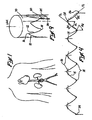
- Figures 1-6 show an endoluminal graft 100 of the present invention, which comprises a pliable tube 22 having a plurality of radially expandable ring members 10 affixed thereto.
- the radially expandable ring members 10 combine to form a graft anchoring system (i.e., a series of individual ring members 10) which, when radially expanded within the lumen of an anatomical conduit, will exert outward force against the surrounding wall of the anatomical conduit to hold the endoluminal graft 100 in a substantially fixed position therewithin.
- each ring member 10 comprises a series of curvilinear segments 12, 14 which extend, in zig-zag fashion, between apices 16, 18.
- a tangent line TL is projectable in relation to each curvilinear segment 12 or 14, and the direction in which the curvilinear segment 12, 14 diverges from its tangent line TL is herein referred to as its direction of curvature DC.
- a center of radius CR is definable within each apex 16, 18, and a longitudinal apical axis LAA may be projected through each center of radius CR, as shown.
- An internal angle A 1 of preferably about 37.5 degrees, and an external angle A 2 of preferably about 70 degrees, are defined between each longitudinal apical axis LAA and the adjacent tangent lines TL which relate to the curvilinear segments 12, 14 on either side of that longitudinal apical axis LAA.
- the values of the internal angle A 1 and the external angle A 2 are not limited to the described preferred embodiments and it will be understood by those skilled in the art that other values also within the scope of the present invention.
- each ring member 10 As shown in Figure 9 , the individual curvilinear segments 12, 14 of each ring member 10 are affixed to or continuous with one another, and are formed about a longitudinal axis LA to form a ring. Depending on the physical properties of the material of which the ring members 10 are formed, the ring members 10 may be either pressure expandable or self expanding.
- Ring members 10 of the pressure-expandable (i.e., "passive expandable”) variety may be formed of plastically deformable material (e.g., stainless steel or ElgiloyTM) which is compressible and plastically deformable to a first (radially compact) diameter and remains stable in such first diameter until such time as outwardly directed pressure is applied thereto (e.g., by inflation of a balloon positioned within the interior of the radially collapsed ring member) to cause radial expansion and resultant plastic deformation to a second (operative) diameter.
- plastically deformable material e.g., stainless steel or ElgiloyTM
- Ring members 10 of the self-expanding variety may be formed of resilient or shape memory material (e.g., spring steel or NitinolTM) which is capable of self-expanding from its first (radially compact) diameter to its second (operative) diameter without the exertion of outwardly directed force thereagainst
- resilient or shape memory material e.g., spring steel or NitinolTM
- Each ring member 10 may thus be used individually as a radially expandable intraluminal stent, whereby the alternating zig-zag configuration of the curvilinear members 12, 14 will form a support scaffold which will prevent surrounding tissue from invading the interior thereof.
- the ring members 10 comprise stents which may be implanted in blood vessels or other luminal anatomical structures to maintain patency thereof.
- the ring member 10 When it is desired to use a ring member 10 as a stent, the ring member 10 may be initially mounted upon or within a delivery catheter for introduction into, and implantation within, the desired anatomical structure. In pressure-expandable embodiments, by way of example and not limitation this may be accomplished by mounting the ring member 10 in a radially compressed state upon a balloon catheter, while the balloon of the catheter is deflated. Thereafter, the catheter is inserted and advanced through the body lumens (e.g., blood vessels) until the ring member 10 is positioned at the desired site of implantation. Thereafter, the balloon of the catheter is inflated causing the ring member 10 to radially expand until it engages the surrounding wall of the anatomical structure (e.g., blood vessel).
- the body lumens e.g., blood vessels
- the balloon is deflated and the catheter is removed, leaving the ring member implanted as a stent within the luminal anatomical structure (e.g., blood vessel).
- a stent within the luminal anatomical structure (e.g., blood vessel).
- Self-expanding embodiments and any known methods of their implantation are also within the scope of the present invention.
- FIGS 1-3 and 5-6 show an endoluminal graft 100 wherein a plurality of the ring members 10 of the present invention are used to form a graft anchoring system.
- the endoluminal graft 100 comprises a pliable tube graft 22 having a series of the ring members 10 affixed to the tube graft 22 at spaced-apart locations or intervals, as shown.
- the apices 16, 18 of the ring members 10 are preferably in direct alignment with one another and the curvilinear segments 12, 14 are also substantially aligned and are of the substantially the same direction of curvature DC.
- the pliable tube graft 22 may be formed of any suitable material, including but not limited to woven polyester, expanded polytetrafluoroethylene (ePTFE), etc.
- the tube graft 22 is formed of woven polyester and the individual ring members 10 are threaded through slits 40 formed in the tube graft 22 such that the ring members 10 will be held in substantially fixed positions within the tube graft 22.
- the ring members 10 may be unconnected to one another other than by way of their common attachment to the pliable tube graft. On the other hand, if desired, they may be attached to one another other than by way of their common attachment to the pliable tube graft.
- terminal ring members 10 E located at either end of the endoluminal graft 100 such that their first apices 16 protrude beyond the end of the tube graft 22, as particularly shown in Figures 5 and 6 .
- the protruding portions of the terminal ring members 10 E may be bent outwardly in the manner indicated by phantom lines on Figure 5 , to enhance the frictional engagement of those terminal ring members 10 E with the tissue of the surrounding wall of the anatomical structure.
- the protruding portions 10 E are described in great details in U.S. Patent No. 5,782,904 to White et al. , which is incorporated herein by reference.
- a ring member 10 of the present invention is formed from a single piece of wire 57, using the fixture apparatus and method shown in figures 7-9 .
- the preferred fixture apparatus 50 comprises a backboard 52 which has a flat surface 53 and a plurality of wire-forming block members 54 mounted on such flat surface 56.
- Each block member 54 has a curved wire-abutting edge 56, an apical tip 58, and an apical trough 60.
- the block members 54 are mounted on the back board 52 such that the apical tip 58 of one block member 54 is in close-spaced juxtaposition with the apical trough 60 of the next block member 54, as shown.
- the distance between the apical tip 58 of one block member 54 and the apical trough 60 of the next block member 54 is approximately equal to the diameter of the wire 57.
- a preferred wire 57 for use in forming the ring members 10 is an alloy wire available commercially as ElgiloyTM wire from Elgiloy, Elgin, Illinois.
- Other wires which may be useable include stainless steel wire and other implantable metals.
- the wire 57 is threaded between the block members 54 such that the wire 57 abuts against the curved surfaces 56 to form the curvilinear segments 12, 14, and is interposed between the adjacent apical tips 58 and apical troughs 60 to form the first and second apices 16, 18. In this manner, the wire 57 assumes the desired flattened wireform configuration shown in Figure 4 .
- the wire 57 is removed from the fixture apparatus 52 and is the formed about a cylindrical mandrel 70 to impart the desired ring configuration.
- the free ends tails 24, 26 of the wire 57 are in side by side juxtaposition.
- Such free end tails 24, 26 are then twined about one another to overlap and a sleeve member 30 is crimped thereabout to firmly connect the twined portions of the free end tails 24, 26 immediately adjacent the associated second apex 18.
- any portions of the free end tails 24, 26 which protrude from the crimped sleeve member 30 may be cut away, and the finished ring member 10 is removed from the mandrel 70.
- the plurality of curvilinear segments of each ring member may be initially formed as separate, curvilinear segments and subsequently connected to one another to form that ring member.
Landscapes
- Health & Medical Sciences (AREA)
- Engineering & Computer Science (AREA)
- Biomedical Technology (AREA)
- Heart & Thoracic Surgery (AREA)
- Public Health (AREA)
- Transplantation (AREA)
- Cardiology (AREA)
- Veterinary Medicine (AREA)
- Oral & Maxillofacial Surgery (AREA)
- Vascular Medicine (AREA)
- Life Sciences & Earth Sciences (AREA)
- Animal Behavior & Ethology (AREA)
- General Health & Medical Sciences (AREA)
- Gastroenterology & Hepatology (AREA)
- Pulmonology (AREA)
- Prostheses (AREA)
- Media Introduction/Drainage Providing Device (AREA)
Abstract
Claims (11)
- Forme de fil (10) pour stents ou greffons médicaux, comprenant :une forme de fil (10) annulaire définissant un axe central et incluant un fil distinct façonné avec une pluralité de formes en ondes curvilignes, les formes d'onde ayant une pluralité de premiers sommets (16) coplanaires et une pluralité de seconds sommets (18) coplanaires, les premiers et seconds sommets étant alternés et s'étendant en des directions opposées, et une pluralité de segments curvilignes (12, 14) s'étendant entre et raccordant les premiers et seconds sommets alternés,caractérisée par le fait que les segments curvilignes ont chacun la même direction de courbure, de telle sorte que lorsque la forme de fil est écrasée en une configuration écrasée radialement, les segments curvilignes (12, 14) adjacents soient nichés les uns dans les autres en contact en about.
- Forme de fil (10) selon la revendication 1, dans laquelle les premiers et seconds sommets (16, 18) sont curvilignes et ont des rayons de courbure et un centre de rayon correspondant.
- Forme de fil (10) selon la revendication 2, dans laquelle chaque segment curviligne (12, 14) se raccorde aux premiers et seconds sommets adjacents au niveau de points de tangence le long des rayons de courbure respectifs des premiers et seconds sommets (16, 18).
- Greffon intraluminal, comprenant :un tube pliable biocompatible (22), etau moins l'une des formes de fil (10) annulaires selon l'une quelconque des revendications précédentes, raccordée au tube pliable.
- Greffon selon la revendication 4, dans lequel la forme de fil (10) est formée au moins en partie de matériau élastique de telle sorte que ladite forme de fil s'étende automatiquement en une configuration étendue radialement lorsqu'elle n'est pas contrainte.
- Greffon selon la revendication 4, dans lequel la forme de fil (10) est formée d'un matériau à mémoire de forme.
- Greffon selon la revendication 4, dans lequel ladite forme de fil (10) est au moins en partie formée d'un matériau malléable qui est initialement formé en ladite configuration compacte radialement, et est plastiquement déformable pour prendre ladite configuration étendue radialement.
- Greffon selon la revendication 4, dans lequel l'échafaudage de support inclut une pluralité de formes de fil (10) écartées les unes des autres.
- Greffon selon la revendication 8, dans lequel le greffon est droit et les axes centraux de la pluralité de formes de fil (10) sont co-linéaires.
- Greffon selon la revendication 8, dans lequel les premiers sommets de la pluralité de formes de fil (10) sont alignés axialement.
- Greffon selon la revendication 4, dans lequel la forme de fil (10) est vissée par des fentes formées dans le tube pliable (22), de telle sorte que la forme de fil (10) est maintenue dans une position substantiellement fixée dans le tube (22).
Applications Claiming Priority (3)
| Application Number | Priority Date | Filing Date | Title |
|---|---|---|---|
| US163831 | 1998-09-30 | ||
| US09/163,831 US6071307A (en) | 1998-09-30 | 1998-09-30 | Endoluminal grafts having continuously curvilinear wireforms |
| PCT/US1999/022400 WO2000018324A2 (fr) | 1998-09-30 | 1999-09-24 | Greffes endoluminales comportant des formes de fil curvilignes continues |
Publications (3)
| Publication Number | Publication Date |
|---|---|
| EP1124505A2 EP1124505A2 (fr) | 2001-08-22 |
| EP1124505B1 EP1124505B1 (fr) | 2005-03-23 |
| EP1124505B2 true EP1124505B2 (fr) | 2009-01-28 |
Family
ID=22591772
Family Applications (1)
| Application Number | Title | Priority Date | Filing Date |
|---|---|---|---|
| EP99951621A Expired - Lifetime EP1124505B2 (fr) | 1998-09-30 | 1999-09-24 | Greffes endoluminales comportant des formes de fil curvilignes continues |
Country Status (7)
| Country | Link |
|---|---|
| US (1) | US6071307A (fr) |
| EP (1) | EP1124505B2 (fr) |
| JP (2) | JP2002531148A (fr) |
| AU (1) | AU762866B2 (fr) |
| CA (1) | CA2345962C (fr) |
| DE (1) | DE69924400T3 (fr) |
| WO (1) | WO2000018324A2 (fr) |
Families Citing this family (63)
| Publication number | Priority date | Publication date | Assignee | Title |
|---|---|---|---|---|
| US6331188B1 (en) * | 1994-08-31 | 2001-12-18 | Gore Enterprise Holdings, Inc. | Exterior supported self-expanding stent-graft |
| US6626938B1 (en) * | 2000-11-16 | 2003-09-30 | Cordis Corporation | Stent graft having a pleated graft member |
| US6887268B2 (en) * | 1998-03-30 | 2005-05-03 | Cordis Corporation | Extension prosthesis for an arterial repair |
| US7314477B1 (en) | 1998-09-25 | 2008-01-01 | C.R. Bard Inc. | Removable embolus blood clot filter and filter delivery unit |
| AUPQ302999A0 (en) | 1999-09-23 | 1999-10-21 | Endogad Research Pty Limited | Pre-shaped intraluminal graft |
| US6849088B2 (en) * | 1998-09-30 | 2005-02-01 | Edwards Lifesciences Corporation | Aorto uni-iliac graft |
| US6325820B1 (en) | 1998-11-16 | 2001-12-04 | Endotex Interventional Systems, Inc. | Coiled-sheet stent-graft with exo-skeleton |
| US6322585B1 (en) | 1998-11-16 | 2001-11-27 | Endotex Interventional Systems, Inc. | Coiled-sheet stent-graft with slidable exo-skeleton |
| AU2007200411B2 (en) * | 1999-01-22 | 2008-05-29 | W. L. Gore & Associates, Inc. | Low profile stent and graft combination |
| US6278079B1 (en) * | 1999-02-09 | 2001-08-21 | Edwards Lifesciences Corp. | Laser cutting of fabric grafts |
| US6805704B1 (en) | 2000-06-26 | 2004-10-19 | C. R. Bard, Inc. | Intraluminal stents |
| US7229472B2 (en) * | 2000-11-16 | 2007-06-12 | Cordis Corporation | Thoracic aneurysm repair prosthesis and system |
| US20040106972A1 (en) * | 2000-11-20 | 2004-06-03 | Deaton David H. | Fenestrated endovascular graft |
| US6641607B1 (en) | 2000-12-29 | 2003-11-04 | Advanced Cardiovascular Systems, Inc. | Double tube stent |
| AUPR847301A0 (en) * | 2001-10-26 | 2001-11-15 | Cook Incorporated | Endoluminal prostheses for curved lumens |
| US7331992B2 (en) * | 2002-02-20 | 2008-02-19 | Bard Peripheral Vascular, Inc. | Anchoring device for an endoluminal prosthesis |
| US9204956B2 (en) | 2002-02-20 | 2015-12-08 | C. R. Bard, Inc. | IVC filter with translating hooks |
| US6939369B2 (en) * | 2002-04-03 | 2005-09-06 | Cook Incorporated | Intraluminal graft assembly and vessel repair system |
| MXPA05001845A (es) | 2002-08-15 | 2005-11-17 | Gmp Cardiac Care Inc | Injerto de espiral con rieles. |
| US20040059406A1 (en) | 2002-09-20 | 2004-03-25 | Cully Edward H. | Medical device amenable to fenestration |
| US6929663B2 (en) * | 2003-03-26 | 2005-08-16 | Boston Scientific Scimed, Inc. | Longitudinally expanding medical device |
| DE10337739B4 (de) * | 2003-08-12 | 2009-11-26 | Jotec Gmbh | Stent zur Implantation in ein Blutgefäß, insbesondere im Bereich des Aortenbogens |
| US11596537B2 (en) | 2003-09-03 | 2023-03-07 | Bolton Medical, Inc. | Delivery system and method for self-centering a proximal end of a stent graft |
| US11259945B2 (en) | 2003-09-03 | 2022-03-01 | Bolton Medical, Inc. | Dual capture device for stent graft delivery system and method for capturing a stent graft |
| US20080264102A1 (en) | 2004-02-23 | 2008-10-30 | Bolton Medical, Inc. | Sheath Capture Device for Stent Graft Delivery System and Method for Operating Same |
| US8292943B2 (en) | 2003-09-03 | 2012-10-23 | Bolton Medical, Inc. | Stent graft with longitudinal support member |
| US7763063B2 (en) | 2003-09-03 | 2010-07-27 | Bolton Medical, Inc. | Self-aligning stent graft delivery system, kit, and method |
| US9198786B2 (en) | 2003-09-03 | 2015-12-01 | Bolton Medical, Inc. | Lumen repair device with capture structure |
| US8500792B2 (en) | 2003-09-03 | 2013-08-06 | Bolton Medical, Inc. | Dual capture device for stent graft delivery system and method for capturing a stent graft |
| US20070198078A1 (en) | 2003-09-03 | 2007-08-23 | Bolton Medical, Inc. | Delivery system and method for self-centering a Proximal end of a stent graft |
| US7704267B2 (en) | 2004-08-04 | 2010-04-27 | C. R. Bard, Inc. | Non-entangling vena cava filter |
| CA3029306C (fr) | 2005-05-12 | 2020-12-29 | C.R. Bard Inc. | Filtre amovible pour caillot sanguin ou embole |
| CA2616818C (fr) | 2005-08-09 | 2014-08-05 | C.R. Bard, Inc. | Filtre pour caillots de sang generateurs d'embolie et systeme de mise en place |
| CA2940038C (fr) | 2005-11-18 | 2018-08-28 | C.R. Bard, Inc. | Filtre de veine cave dote d'un filament |
| EA013625B1 (ru) * | 2006-01-13 | 2010-06-30 | И.Б.С. Интернэшнл Байомедикал Системз С.П.А. | Эндоваскулярный протез и способ его изготовления |
| US8333785B2 (en) * | 2006-05-02 | 2012-12-18 | C. R. Bard, Inc. | IVC filter with translating hooks |
| US10188496B2 (en) | 2006-05-02 | 2019-01-29 | C. R. Bard, Inc. | Vena cava filter formed from a sheet |
| CA2655158A1 (fr) | 2006-06-05 | 2007-12-13 | C.R. Bard Inc. | Filtre pour caillots sanguins generateurs d'embolie utilisable avec un systeme de mise en place unique ou un systeme de retrait unique via un acces femoral ou jugulaire |
| ATE461675T1 (de) * | 2006-10-24 | 2010-04-15 | Cook Inc | Stentelement |
| US9622888B2 (en) * | 2006-11-16 | 2017-04-18 | W. L. Gore & Associates, Inc. | Stent having flexibly connected adjacent stent elements |
| US8142490B2 (en) * | 2007-10-24 | 2012-03-27 | Cordis Corporation | Stent segments axially connected by thin film |
| WO2009082718A1 (fr) * | 2007-12-21 | 2009-07-02 | Feinstein Ara J | Dispositifs, systèmes et procédés permettant de réparer des défauts vasculaires |
| US20140005586A1 (en) * | 2007-12-21 | 2014-01-02 | Ara J. Feinstein | Devices, systems, and methods for repair of vascular defects |
| US8574284B2 (en) | 2007-12-26 | 2013-11-05 | Cook Medical Technologies Llc | Low profile non-symmetrical bare alignment stents with graft |
| GB2475494B (en) * | 2009-11-18 | 2011-11-23 | Cook William Europ | Stent graft and introducer assembly |
| US9180030B2 (en) | 2007-12-26 | 2015-11-10 | Cook Medical Technologies Llc | Low profile non-symmetrical stent |
| US9226813B2 (en) | 2007-12-26 | 2016-01-05 | Cook Medical Technologies Llc | Low profile non-symmetrical stent |
| US8992593B2 (en) * | 2007-12-26 | 2015-03-31 | Cook Medical Technologies Llc | Apparatus and methods for deployment of a modular stent-graft system |
| US8728145B2 (en) | 2008-12-11 | 2014-05-20 | Cook Medical Technologies Llc | Low profile non-symmetrical stents and stent-grafts |
| GB2476451A (en) * | 2009-11-19 | 2011-06-29 | Cook William Europ | Stent Graft |
| US8926688B2 (en) | 2008-01-11 | 2015-01-06 | W. L. Gore & Assoc. Inc. | Stent having adjacent elements connected by flexible webs |
| EP3219292B1 (fr) * | 2008-06-30 | 2019-08-14 | Bolton Medical Inc. | Systèmes de traitement des anévrismes aortiques abdominaux |
| US20100100170A1 (en) * | 2008-10-22 | 2010-04-22 | Boston Scientific Scimed, Inc. | Shape memory tubular stent with grooves |
| CN102413794B (zh) | 2009-03-13 | 2017-02-08 | 波顿医疗公司 | 用于在手术部位部署腔内假体的系统和方法 |
| WO2010107681A1 (fr) | 2009-03-16 | 2010-09-23 | Med Institute, Inc. | Stent hybride et procédé de fabrication d'un tel stent |
| GB2470041B (en) * | 2009-05-06 | 2011-05-18 | Cook William Europ | Stent graft |
| CA2769208C (fr) | 2009-07-29 | 2017-10-31 | C.R. Bard, Inc. | Filtre tubulaire |
| US9757263B2 (en) * | 2009-11-18 | 2017-09-12 | Cook Medical Technologies Llc | Stent graft and introducer assembly |
| CN104363862B (zh) | 2012-04-12 | 2016-10-05 | 波顿医疗公司 | 血管假体输送装置及使用方法 |
| US9439751B2 (en) | 2013-03-15 | 2016-09-13 | Bolton Medical, Inc. | Hemostasis valve and delivery systems |
| US10299948B2 (en) | 2014-11-26 | 2019-05-28 | W. L. Gore & Associates, Inc. | Balloon expandable endoprosthesis |
| US10568752B2 (en) | 2016-05-25 | 2020-02-25 | W. L. Gore & Associates, Inc. | Controlled endoprosthesis balloon expansion |
| JP7039957B2 (ja) * | 2017-11-24 | 2022-03-23 | 株式会社ジェイ・エム・エス | ステント |
Family Cites Families (38)
| Publication number | Priority date | Publication date | Assignee | Title |
|---|---|---|---|---|
| US2978787A (en) * | 1957-04-18 | 1961-04-11 | Meadox Medicals Inc | Synthetic vascular implants and the manufacture thereof |
| US3481177A (en) * | 1967-09-29 | 1969-12-02 | Lear Siegler Inc | Wire bending assembly |
| US4136718A (en) * | 1977-12-12 | 1979-01-30 | Ignatiev Alexei K | Apparatus for making serpentiform springs |
| US5669936A (en) * | 1983-12-09 | 1997-09-23 | Endovascular Technologies, Inc. | Endovascular grafting system and method for use therewith |
| US5104399A (en) * | 1986-12-10 | 1992-04-14 | Endovascular Technologies, Inc. | Artificial graft and implantation method |
| US5123917A (en) * | 1990-04-27 | 1992-06-23 | Lee Peter Y | Expandable intraluminal vascular graft |
| US5360443A (en) * | 1990-06-11 | 1994-11-01 | Barone Hector D | Aortic graft for repairing an abdominal aortic aneurysm |
| US5064435A (en) * | 1990-06-28 | 1991-11-12 | Schneider (Usa) Inc. | Self-expanding prosthesis having stable axial length |
| US5135536A (en) * | 1991-02-05 | 1992-08-04 | Cordis Corporation | Endovascular stent and method |
| CA2065634C (fr) * | 1991-04-11 | 1997-06-03 | Alec A. Piplani | Greffon endovasculaire ayant une bifurcation et appareil et methode servant a le deployer |
| US5527354A (en) * | 1991-06-28 | 1996-06-18 | Cook Incorporated | Stent formed of half-round wire |
| AU669338B2 (en) * | 1991-10-25 | 1996-06-06 | Cook Incorporated | Expandable transluminal graft prosthesis for repair of aneurysm and method for implanting |
| CA2079417C (fr) * | 1991-10-28 | 2003-01-07 | Lilip Lau | Empreintes extensibles et leur methode de fabrication |
| US5316023A (en) * | 1992-01-08 | 1994-05-31 | Expandable Grafts Partnership | Method for bilateral intra-aortic bypass |
| ES2217270T3 (es) * | 1993-09-30 | 2004-11-01 | Endogad Research Pty Limited | Injerto endoluminal. |
| EP0657147B1 (fr) * | 1993-11-04 | 1999-08-04 | C.R. Bard, Inc. | Prothèse vasculaire non migrante |
| AU1091095A (en) * | 1993-11-08 | 1995-05-29 | Harrison M. Lazarus | Intraluminal vascular graft and method |
| US5443497A (en) * | 1993-11-22 | 1995-08-22 | The Johns Hopkins University | Percutaneous prosthetic by-pass graft and method of use |
| JP2703510B2 (ja) * | 1993-12-28 | 1998-01-26 | アドヴァンスド カーディオヴァスキュラー システムズ インコーポレーテッド | 拡大可能なステント及びその製造方法 |
| US5554181A (en) * | 1994-05-04 | 1996-09-10 | Regents Of The University Of Minnesota | Stent |
| DE69533993T2 (de) * | 1994-06-08 | 2006-04-27 | CardioVascular Concepts, Inc., Portola Valley | Endoluminales Transplantat |
| US5575816A (en) * | 1994-08-12 | 1996-11-19 | Meadox Medicals, Inc. | High strength and high density intraluminal wire stent |
| US5575817A (en) * | 1994-08-19 | 1996-11-19 | Martin; Eric C. | Aorto femoral bifurcation graft and method of implantation |
| US5609605A (en) * | 1994-08-25 | 1997-03-11 | Ethicon, Inc. | Combination arterial stent |
| US5591230A (en) * | 1994-09-07 | 1997-01-07 | Global Therapeutics, Inc. | Radially expandable stent |
| AU708360B2 (en) * | 1994-09-15 | 1999-08-05 | C.R. Bard Inc. | Hooked endoprosthesis |
| AU3783195A (en) * | 1994-11-15 | 1996-05-23 | Advanced Cardiovascular Systems Inc. | Intraluminal stent for attaching a graft |
| US5630829A (en) * | 1994-12-09 | 1997-05-20 | Intervascular, Inc. | High hoop strength intraluminal stent |
| US5683449A (en) * | 1995-02-24 | 1997-11-04 | Marcade; Jean Paul | Modular bifurcated intraluminal grafts and methods for delivering and assembling same |
| US5591197A (en) * | 1995-03-14 | 1997-01-07 | Advanced Cardiovascular Systems, Inc. | Expandable stent forming projecting barbs and method for deploying |
| DK171865B1 (da) * | 1995-09-11 | 1997-07-21 | Cook William Europ | Ekspanderbar endovasculær stent |
| US6099558A (en) * | 1995-10-10 | 2000-08-08 | Edwards Lifesciences Corp. | Intraluminal grafting of a bifuricated artery |
| US5776161A (en) * | 1995-10-16 | 1998-07-07 | Instent, Inc. | Medical stents, apparatus and method for making same |
| US5709701A (en) * | 1996-05-30 | 1998-01-20 | Parodi; Juan C. | Apparatus for implanting a prothesis within a body passageway |
| US5676697A (en) * | 1996-07-29 | 1997-10-14 | Cardiovascular Dynamics, Inc. | Two-piece, bifurcated intraluminal graft for repair of aneurysm |
| US5925061A (en) * | 1997-01-13 | 1999-07-20 | Gore Enterprise Holdings, Inc. | Low profile vascular stent |
| US5824055A (en) * | 1997-03-25 | 1998-10-20 | Endotex Interventional Systems, Inc. | Stent graft delivery system and methods of use |
| US5931866A (en) * | 1998-02-24 | 1999-08-03 | Frantzen; John J. | Radially expandable stent featuring accordion stops |
-
1998
- 1998-09-30 US US09/163,831 patent/US6071307A/en not_active Expired - Lifetime
-
1999
- 1999-09-24 AU AU64025/99A patent/AU762866B2/en not_active Expired
- 1999-09-24 JP JP2000571847A patent/JP2002531148A/ja active Pending
- 1999-09-24 CA CA002345962A patent/CA2345962C/fr not_active Expired - Lifetime
- 1999-09-24 DE DE69924400T patent/DE69924400T3/de not_active Expired - Lifetime
- 1999-09-24 EP EP99951621A patent/EP1124505B2/fr not_active Expired - Lifetime
- 1999-09-24 WO PCT/US1999/022400 patent/WO2000018324A2/fr active IP Right Grant
-
2008
- 2008-03-31 JP JP2008094313A patent/JP2008173499A/ja active Pending
Non-Patent Citations (1)
| Title |
|---|
| None † |
Also Published As
| Publication number | Publication date |
|---|---|
| JP2008173499A (ja) | 2008-07-31 |
| WO2000018324A3 (fr) | 2000-08-17 |
| AU762866B2 (en) | 2003-07-10 |
| CA2345962A1 (fr) | 2000-04-06 |
| DE69924400D1 (de) | 2005-04-28 |
| JP2002531148A (ja) | 2002-09-24 |
| US6071307A (en) | 2000-06-06 |
| WO2000018324A2 (fr) | 2000-04-06 |
| EP1124505B1 (fr) | 2005-03-23 |
| WO2000018324A9 (fr) | 2000-10-05 |
| DE69924400T3 (de) | 2009-07-23 |
| AU6402599A (en) | 2000-04-17 |
| EP1124505A2 (fr) | 2001-08-22 |
| CA2345962C (fr) | 2008-02-19 |
| DE69924400T2 (de) | 2005-08-11 |
Similar Documents
| Publication | Publication Date | Title |
|---|---|---|
| EP1124505B2 (fr) | Greffes endoluminales comportant des formes de fil curvilignes continues | |
| EP1009326B1 (fr) | Endoprothese spirale maillee | |
| US6270524B1 (en) | Flexible, radially expansible luminal prostheses | |
| EP1776066B1 (fr) | Stent pourvu d'entretoises arquées | |
| US7998194B2 (en) | Mechanism for securing to a corporeal lumen and method of manufacturing | |
| US5843168A (en) | Double wave stent with strut | |
| US6699277B1 (en) | Stent with cover connectors | |
| EP0556850B1 (fr) | Stent instraluminaire | |
| US6325820B1 (en) | Coiled-sheet stent-graft with exo-skeleton | |
| EP0357003B2 (fr) | Endoprothèse expansible radialement | |
| EP1168985B1 (fr) | Prothese endovasculaire a feuille enroulee, qui comporte un exosquelette coulissant | |
| US7887580B2 (en) | Anchoring device for an endoluminal prosthesis | |
| EP1700581A2 (fr) | Stent avec des boucles pour la fixation d'une greffe | |
| US20090149946A1 (en) | Stent having at least one barb and methods of manufacture | |
| EP1263348B1 (fr) | Prothese intravasculaire | |
| JPH10508775A (ja) | 動脈瘤治療のための送達カテーテルおよび移植片 |
Legal Events
| Date | Code | Title | Description |
|---|---|---|---|
| PUAI | Public reference made under article 153(3) epc to a published international application that has entered the european phase |
Free format text: ORIGINAL CODE: 0009012 |
|
| 17P | Request for examination filed |
Effective date: 20010427 |
|
| AK | Designated contracting states |
Kind code of ref document: A2 Designated state(s): AT BE CH CY DE DK ES FI FR GB GR IE IT LI LU MC NL PT SE |
|
| AX | Request for extension of the european patent |
Free format text: AL;LT;LV;MK;RO;SI |
|
| 17Q | First examination report despatched |
Effective date: 20030807 |
|
| RBV | Designated contracting states (corrected) |
Designated state(s): DE FR GB IT |
|
| GRAP | Despatch of communication of intention to grant a patent |
Free format text: ORIGINAL CODE: EPIDOSNIGR1 |
|
| GRAS | Grant fee paid |
Free format text: ORIGINAL CODE: EPIDOSNIGR3 |
|
| GRAA | (expected) grant |
Free format text: ORIGINAL CODE: 0009210 |
|
| AK | Designated contracting states |
Kind code of ref document: B1 Designated state(s): DE FR GB IT |
|
| PG25 | Lapsed in a contracting state [announced via postgrant information from national office to epo] |
Ref country code: IT Free format text: LAPSE BECAUSE OF FAILURE TO SUBMIT A TRANSLATION OF THE DESCRIPTION OR TO PAY THE FEE WITHIN THE PRE;WARNING: LAPSES OF ITALIAN PATENTS WITH EFFECTIVE DATE BEFORE 2007 MAY HAVE OCCURRED AT ANY TIME BEFORE 2007. THE CORRECT EFFECTIVE DATE MAY BE DIFFERENT FROM THE ONE RECORDED.SCRIBED TIME-LIMIT Effective date: 20050323 |
|
| REG | Reference to a national code |
Ref country code: GB Ref legal event code: FG4D |
|
| REG | Reference to a national code |
Ref country code: IE Ref legal event code: FG4D |
|
| REF | Corresponds to: |
Ref document number: 69924400 Country of ref document: DE Date of ref document: 20050428 Kind code of ref document: P |
|
| PLBI | Opposition filed |
Free format text: ORIGINAL CODE: 0009260 |
|
| PLAX | Notice of opposition and request to file observation + time limit sent |
Free format text: ORIGINAL CODE: EPIDOSNOBS2 |
|
| 26 | Opposition filed |
Opponent name: BOSTON SCIENTIFIC CORPORATION Effective date: 20051222 |
|
| ET | Fr: translation filed | ||
| PLAF | Information modified related to communication of a notice of opposition and request to file observations + time limit |
Free format text: ORIGINAL CODE: EPIDOSCOBS2 |
|
| PLAF | Information modified related to communication of a notice of opposition and request to file observations + time limit |
Free format text: ORIGINAL CODE: EPIDOSCOBS2 |
|
| PLBB | Reply of patent proprietor to notice(s) of opposition received |
Free format text: ORIGINAL CODE: EPIDOSNOBS3 |
|
| PLAB | Opposition data, opponent's data or that of the opponent's representative modified |
Free format text: ORIGINAL CODE: 0009299OPPO |
|
| PUAH | Patent maintained in amended form |
Free format text: ORIGINAL CODE: 0009272 |
|
| STAA | Information on the status of an ep patent application or granted ep patent |
Free format text: STATUS: PATENT MAINTAINED AS AMENDED |
|
| 27A | Patent maintained in amended form |
Effective date: 20090128 |
|
| AK | Designated contracting states |
Kind code of ref document: B2 Designated state(s): DE FR GB IT |
|
| REG | Reference to a national code |
Ref country code: FR Ref legal event code: PLFP Year of fee payment: 18 |
|
| REG | Reference to a national code |
Ref country code: FR Ref legal event code: PLFP Year of fee payment: 19 |
|
| REG | Reference to a national code |
Ref country code: FR Ref legal event code: PLFP Year of fee payment: 20 |
|
| PGFP | Annual fee paid to national office [announced via postgrant information from national office to epo] |
Ref country code: DE Payment date: 20180821 Year of fee payment: 20 Ref country code: FR Payment date: 20180822 Year of fee payment: 20 |
|
| PGFP | Annual fee paid to national office [announced via postgrant information from national office to epo] |
Ref country code: GB Payment date: 20180823 Year of fee payment: 20 |
|
| REG | Reference to a national code |
Ref country code: DE Ref legal event code: R071 Ref document number: 69924400 Country of ref document: DE |
|
| REG | Reference to a national code |
Ref country code: GB Ref legal event code: PE20 Expiry date: 20190923 |
|
| PG25 | Lapsed in a contracting state [announced via postgrant information from national office to epo] |
Ref country code: GB Free format text: LAPSE BECAUSE OF EXPIRATION OF PROTECTION Effective date: 20190923 |