EP1124289A2 - Elektromagnetisch abgeschirmete Zugentlastungsvorrichtung und Staubdeckel - Google Patents
Elektromagnetisch abgeschirmete Zugentlastungsvorrichtung und Staubdeckel Download PDFInfo
- Publication number
- EP1124289A2 EP1124289A2 EP01102641A EP01102641A EP1124289A2 EP 1124289 A2 EP1124289 A2 EP 1124289A2 EP 01102641 A EP01102641 A EP 01102641A EP 01102641 A EP01102641 A EP 01102641A EP 1124289 A2 EP1124289 A2 EP 1124289A2
- Authority
- EP
- European Patent Office
- Prior art keywords
- boot
- strain relief
- emi
- distal end
- shield
- Prior art date
- Legal status (The legal status is an assumption and is not a legal conclusion. Google has not performed a legal analysis and makes no representation as to the accuracy of the status listed.)
- Withdrawn
Links
- 239000000428 dust Substances 0.000 title claims abstract description 33
- 230000005540 biological transmission Effects 0.000 claims abstract description 45
- 230000005670 electromagnetic radiation Effects 0.000 claims abstract description 16
- 230000002452 interceptive effect Effects 0.000 claims abstract description 15
- 238000000034 method Methods 0.000 claims abstract description 7
- 239000004020 conductor Substances 0.000 claims description 7
- 229920001971 elastomer Polymers 0.000 claims description 5
- 239000000806 elastomer Substances 0.000 claims description 4
- 239000000696 magnetic material Substances 0.000 claims description 4
- 239000002245 particle Substances 0.000 claims description 4
- 239000000463 material Substances 0.000 description 7
- RYGMFSIKBFXOCR-UHFFFAOYSA-N Copper Chemical compound [Cu] RYGMFSIKBFXOCR-UHFFFAOYSA-N 0.000 description 6
- 229910052802 copper Inorganic materials 0.000 description 6
- 239000010949 copper Substances 0.000 description 6
- 239000013307 optical fiber Substances 0.000 description 6
- 230000002093 peripheral effect Effects 0.000 description 5
- 238000005452 bending Methods 0.000 description 4
- 230000008901 benefit Effects 0.000 description 3
- 239000000203 mixture Substances 0.000 description 2
- 230000007704 transition Effects 0.000 description 2
- 238000004891 communication Methods 0.000 description 1
- 230000007423 decrease Effects 0.000 description 1
- 238000005516 engineering process Methods 0.000 description 1
- 239000000835 fiber Substances 0.000 description 1
- 238000009434 installation Methods 0.000 description 1
- 230000013011 mating Effects 0.000 description 1
- 239000002184 metal Substances 0.000 description 1
- 229910052751 metal Inorganic materials 0.000 description 1
- 230000003287 optical effect Effects 0.000 description 1
- 229920000642 polymer Polymers 0.000 description 1
- 239000000843 powder Substances 0.000 description 1
- 230000008054 signal transmission Effects 0.000 description 1
- 229910000859 α-Fe Inorganic materials 0.000 description 1
Images


Classifications
-
- H—ELECTRICITY
- H01—ELECTRIC ELEMENTS
- H01R—ELECTRICALLY-CONDUCTIVE CONNECTIONS; STRUCTURAL ASSOCIATIONS OF A PLURALITY OF MUTUALLY-INSULATED ELECTRICAL CONNECTING ELEMENTS; COUPLING DEVICES; CURRENT COLLECTORS
- H01R13/00—Details of coupling devices of the kinds covered by groups H01R12/70 or H01R24/00 - H01R33/00
- H01R13/46—Bases; Cases
- H01R13/52—Dustproof, splashproof, drip-proof, waterproof, or flameproof cases
- H01R13/5213—Covers
-
- H—ELECTRICITY
- H01—ELECTRIC ELEMENTS
- H01R—ELECTRICALLY-CONDUCTIVE CONNECTIONS; STRUCTURAL ASSOCIATIONS OF A PLURALITY OF MUTUALLY-INSULATED ELECTRICAL CONNECTING ELEMENTS; COUPLING DEVICES; CURRENT COLLECTORS
- H01R13/00—Details of coupling devices of the kinds covered by groups H01R12/70 or H01R24/00 - H01R33/00
- H01R13/58—Means for relieving strain on wire connection, e.g. cord grip, for avoiding loosening of connections between wires and terminals within a coupling device terminating a cable
-
- H—ELECTRICITY
- H01—ELECTRIC ELEMENTS
- H01R—ELECTRICALLY-CONDUCTIVE CONNECTIONS; STRUCTURAL ASSOCIATIONS OF A PLURALITY OF MUTUALLY-INSULATED ELECTRICAL CONNECTING ELEMENTS; COUPLING DEVICES; CURRENT COLLECTORS
- H01R13/00—Details of coupling devices of the kinds covered by groups H01R12/70 or H01R24/00 - H01R33/00
- H01R13/648—Protective earth or shield arrangements on coupling devices, e.g. anti-static shielding
- H01R13/658—High frequency shielding arrangements, e.g. against EMI [Electro-Magnetic Interference] or EMP [Electro-Magnetic Pulse]
- H01R13/6581—Shield structure
-
- H—ELECTRICITY
- H01—ELECTRIC ELEMENTS
- H01R—ELECTRICALLY-CONDUCTIVE CONNECTIONS; STRUCTURAL ASSOCIATIONS OF A PLURALITY OF MUTUALLY-INSULATED ELECTRICAL CONNECTING ELEMENTS; COUPLING DEVICES; CURRENT COLLECTORS
- H01R13/00—Details of coupling devices of the kinds covered by groups H01R12/70 or H01R24/00 - H01R33/00
- H01R13/648—Protective earth or shield arrangements on coupling devices, e.g. anti-static shielding
- H01R13/658—High frequency shielding arrangements, e.g. against EMI [Electro-Magnetic Interference] or EMP [Electro-Magnetic Pulse]
- H01R13/6591—Specific features or arrangements of connection of shield to conductive members
- H01R13/6596—Specific features or arrangements of connection of shield to conductive members the conductive member being a metal grounding panel
Definitions
- This invention relates to strain relief cable boots and dust covers designed to shield against electromagnetic interference (EMI) generated by high-speed data communication modules, computers and peripheral devices.
- EMI electromagnetic interference
- Transmission cables may be used to transmit data between workstations, mainframes and other computers, as well as provide data connections to mass storage devices and other peripheral devices. Data may be transferred using a variety of transmission cable technologies, including multimode optical fiber cables, single mode optical fiber cables, and copper cables (e.g., twinax and coax copper cables).
- Standard pluggable transceiver modules have been developed to transition between different transfer media and the electronic components inside a computer or peripheral device. A pluggable transceiver module produces a standardized output in accordance with prescribed protocols, regardless of the medium (e.g., optical fiber or copper) through which the data is transmitted or received.
- a transceiver module typically plugs into a transceiver receptacle that extends out of the rear panel of a computer or peripheral device.
- the transceiver receptacle connects the transceiver module to a motherboard or circuit card in the computer or peripheral device.
- Strain relief systems generally protect transmission cables against the stresses that might result during handling of the cables. In particular, strain relief systems protect against stresses that otherwise might impair the signal transmission properties of the cables. Fiber optic cables are especially vulnerable to damage caused by overstressing or kinking, especially near the cable connectors.
- a typical strain relief system includes an elongated boot that extends proximally from the proximal end of the cable connector. The boot surrounds the cable and confines it to a prescribed bend radius range, thereby protecting the cable from excessive bending in the region of the cable-connector interface. The boot may guide the cable proximally from the connector in either a straight or a curved path.
- EMI electromagnetic interference
- Many computers and other high-speed electronic equipment produce significant amount of electromagnetic radiation.
- such equipment typically is housed inside enclosures that are designed to contain the electromagnetic interference (EMI) emissions from the electronic equipment.
- Significant EMI levels may be released through transceiver receptacle openings in the electromagnetically shielded enclosures.
- EMI also is generated by the transceiver modules that plug into the receptacle openings.
- Various complex techniques for reducing the total EMI levels generated at the respective interfaces between the electromagnetically shielded enclosure, the pluggable transceiver module and the transmission cable have been proposed.
- the invention features an EMI-shielding strain relief boot and an EMI-shielding dust cover.
- an EMI-shielding strain relief boot in one aspect of the invention, includes a flexible elongated boot body and an EMI shield.
- the boot body has a proximal end, a distal end, and an inner surface defining a bore sized and arranged to contain an end portion of a transmission cable and an associated cable connector.
- the EMI shield extends along a substantial length of the boot body and is configured to shield a region of the bore from interfering electromagnetic radiation.
- the distal end of the boot body is slidable over the cable connector and is conformable to and envelopable about at least a portion of a pluggable transceiver connector.
- the invention features an EMI-shielding strain relief boot having a flexible elongated boot body and an inner surface defining a bore with a uniform radial dimension.
- the thickness between the inner surface and an exposed outer surface of the boot body tapers from a central longitudinal region toward the proximal end of the boot body and toward the distal end of the boot body.
- the boot also includes a flexible electromagnetic interference (EMI) shield that extends along a substantial length of the boot body to an exposed surface of the distal end of the boot body.
- the EMI shield is formed from an electrically conductive material and is configured to shield a region of the bore from interfering electromagnetic radiation.
- Embodiments may include one or more of the following features.
- the boot body preferably is configured to limit the bend radius of the transmission cable near the cable connector.
- the boot may include a proximal flange coupled to the proximal end of the boot body and defining an opening sized to engage the cable connector while accommodating the end portion of the transmission cable.
- the boot body may include an exposed outer surface with one or more gripping features.
- a distal flange may protrude outwardly away from the bore.
- the distal end of the boot body may have an inner surface that flares outwardly away from the bore.
- the bore may define a curved path through which the transmission cable may extend.
- the EMI shield preferably extends to an exposed surface of the distal end of the boot body.
- the EMI shield preferably comprises an electrical conductor (e.g., a plurality of electrically conductive particles, or a plurality of electrically conductive wires).
- the EMI shield may be incorporated into the boot body.
- the EMI shield may include an electrically conductive layer disposed on the inner surface of the boot body.
- the EMI shield may include magnetic material.
- the boot body preferably comprises an elastomer.
- the invention features a data transmission system, comprising: a pluggable transceiver and an associated transceiver connector; a transmission cable and an associated cable connector sized and arranged to engage the pluggable transceiver connector; and one of the above-defined strain relief boots.
- the distal end of the boot body is slidable over the cable connector and is conformable to and envelopable about an interface between the transmission cable connector and about the pluggable transceiver connector.
- the pluggable transceiver preferably is insertable into a transceiver receptacle having a proximal end defining an opening for receiving the pluggable transceiver.
- the distal end of the boot body is slidable over the cable connector and is conformable to and envelopable about the proximal end of the transceiver receptacle.
- the invention features a method of electromagnetically shielding an opening in an electronic apparatus enclosure.
- an electromagnetic interference shielding strain relief cable boot is attached over a flange protruding from the opening in the electronic apparatus enclosure.
- the dust cover has a flexible elongated dust cover body and an EMI shield.
- the dust cover body has a proximal end, a distal end, and an inner surface defining a bore sized and arranged to contain a flange protruding from an opening in an electronic apparatus enclosure.
- the EMI shield extends along a substantial length of the dust cover body and is configured to shield a region of the bore from interfering electromagnetic radiation.
- the distal end of the dust cover body is conformable to and envelopable about the flange protruding from the opening in the electronic apparatus enclosure.
- the inventive strain relief boots protect transmission cables from damage that might be caused by overstressing or kinking. At the same time, these strain relief boots enable a user to quickly and easily extend the electromagnetic shielding properties of an electromagnetically shielded electronic equipment enclosure to the respective interfaces between the transmission cable, a pluggable transceiver module and a transceiver receptacle extending through the enclosure.
- the inventive EMI-shielding strain relief boot and dust cover provide relatively inexpensive ways to effectively protect against interfering electromagnetic radiation generated near the pluggable transceiver openings in electronic apparatus enclosures.
- FIG. 1A is a diagrammatic exploded cross-sectional side view of a transceiver module, a transceiver receptacle that extends out of the rear panel of an electronic equipment enclosure, and an EMI-shielding strain relief boot disposed over a transmission cable.
- FIG. 1B is a diagrammatic cross-sectional side view of the transmission cable, transceiver module and transceiver receptacle of FIG. 1A connected together with the EMI-shielding strain relief boot disposed over the respective interfaces between the transmission cable, transceiver module and transceiver receptacle.
- FIG. 2 is a diagrammatic cross-sectional side view of the EMI-shielding strain relief boot of FIGS. 1A and 1B.
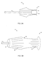
- FIG. 3A is a diagrammatic cross-sectional side view of an alternative EMI-shielding strain relief boot disposed about a transmission cable and an associated cable connector.
- FIG. 3B is a diagrammatic perspective view of the transmission cable and EMI-shielding strain relief boot of FIG. 3A.
- FIGS. 4 and 5 are diagrammatic cross-sectional side views of alternative EMI-shielding strain relief boots.
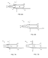
- FIG. 6A is a diagrammatic cross-sectional side view of an EMI-shielding strain relief boot disposed over the interface between a transceiver module and a transceiver receptacle.
- FIG. 6B is a diagrammatic cross-sectional side view of an EMI-shielding strain relief boot disposed over the receptacle opening in the rear panel of an electronic equipment enclosure.
- FIG. 7A is a diagrammatic cross-sectional side view of an EMI-shielding dust cover disposed over the interface between a transceiver module and a transceiver receptacle.
- FIG. 7B is a diagrammatic cross-sectional side view of an EMI-shielding dust cover disposed over the receptacle opening in the rear panel of an electronic equipment enclosure.
- an EMI-shielding strain relief boot (hereinafter "boot") 10 is disposed over an end portion 12 of a transmission cable 14 and an associated cable connector 16.
- Cable connector 16 is configured to plug into a mating connector 18 of a pluggable transceiver module 20 that, in turn, is configured to plug into a receptacle assembly 22.
- Receptacle assembly 22 includes a transceiver receptacle 24 mounted on a circuit card (or motherboard) 26, and a circuit card (or host interface) connector 28 that electrically connects transceiver module 20 to circuit card 26.
- Transceiver receptacle 24 extends through a mounting panel opening 30 in a rear panel 32 of an electromagnetically shielded electronic equipment enclosure.
- Transceiver module 20 is configured to transition between circuit card 26 and the transfer medium of transmission cable 14.
- Transmission cable 14 may be an optical fiber cable (e.g., a single mode or a multimode optical fiber cable) or an electrical (copper) cable (e.g., a twinax or a coax copper cable).
- Cable connector 16 and transceiver connector 18 may conform to any one of a variety of optical and copper interface standards, including HSSDC2-type, RJ-type, SC-type, SG-type, ST-type and LC-type connectors, ribbon cable connectors, and twinax and coaxial cable connectors (e.g., SMA connectors).
- Transceiver receptacle 28 also may conform to a variety of host interface standards, including the MIA (Media Interface Adapter) standard and the recently proposed MSA standard.
- MIA Media Interface Adapter
- transceiver module 20 plugs into transceiver receptacle 24 and cable connector 16 plugs into transceiver module connector 18.
- the distal end of boot 10 slides over cable connector 16 and over at least a portion of transceiver connector 18, up to the rear face of rear panel 32.
- the distal end of boot 10 is conformable to and envelopable about the proximal end of transceiver connector 18 and about the proximal end of transceiver receptacle 24.
- Boot 10 includes a proximal flange 34 that is coupled to the proximal end of the body of boot 10.
- Proximal flange 34 defines an opening 36 sized to engage the proximal face of cable connector 16 while accommodating end portion 12 of transmission cable 14.
- Proximal flange 34 thereby prevents boot 10 from accidentally being pulled off the distal end of transmission cable 14.
- boot 10 includes an EMI shield that extends along a substantial length of boot 10.
- EMI shield also is configured to shield the respective interfaces between transmission cable 14, transceiver module 20 and transceiver receptacle 24.
- the EMI shield includes and electrical conductor that extends up to an exposed surface of the distal end of boot 10 where it electrically couples to transceiver receptacle 24.
- the EMI shield also electrically couples to transceiver module 20 through the exposed surfaces of transceiver connector 18.
- boot 10 extends the electrical shielding properties of the electronic equipment enclosure by shielding mounting panel opening 30, the protruding ends of transceiver receptacle 24 and the respective interfaces between transmission cable 14, transceiver module 20 and transceiver receptacle 24.
- each of these interface features would emit interfering electromagnetic radiation in the vicinity of mounting panel opening 30.
- boot 10 prevents transmission cable 14 from bending near cable connector 16 beyond a prescribed critical bend radius (e.g., about 2.5 cm for an optical fiber transmission cable). In this way, boot 10 protects transmission cable 14 from damage that otherwise might be caused during handling (e.g., overstressing or kinking of transmission cable 14).
- the EMI-shielding and strain relief functions of boot 10 are enabled by tapering the radial thickness of boot 10 from a central region 38 toward the proximal end of boot 10 and toward the distal end of boot 10.
- radial thickness refers to the boot thickness between the inner, bore-defining surface and the exposed outer surface.
- the boot body has an inner surface 40 that defines a bore with a substantially uniform radial dimension from the proximal end to the distal end.
- An exposed outer boot surface 42 diverges outwardly from the proximal end of boot 10 toward central region 38, and converges from central region 38 toward the distal end of boot 10.
- outer surface 42 diverges linearly toward central region 38, and converges more rapidly away from central region 38 (e.g., exponentially or in accordance with a polynomial function).
- boot 10 is relatively stiff near central region 38 and, therefore, highly resistant to lateral stresses.
- the resistance to lateral stresses gradually decreases towards the proximal and distal ends of boot 10.
- Central region 38 and the proximal tapered section prevent transmission cable 14 from bending too sharply near cable connector 16.
- the tapering of the distal section enables the distal end of boot 10 to slide over, envelop and conform to transceiver module connector 18 and to the end of transceiver receptacle 24 and, thereby, enabling boot 10 to shield the respective interfaces between transmission cable 14, transceiver module 20 and transceiver receptacle 24.
- boot 10 has an overall length of about 5 cm to about 10 cm, where the proximal section is about 3 cm to about 9 cm and the distal section is about 1 cm to about 2 cm.
- the proximal cable opening 36 is approximately 1-2 cm in diameter.
- boot 10 includes an EMI shield 44 that extends along a substantial length of the body of boot 10 to shield a region of the bore 46 from interfering electromagnetic radiation.
- EMI shield 44 is configured to shield against EMI by reflecting or absorbing interfering electromagnetic radiation.
- EMI shield 44 may include an electrical conductor, such as a plurality of electrically conductive particles (or powder) incorporated in the body of boot 10, or a plurality of electrically conductive wires extending through the body of boot 10.
- EMI shield includes magnetic material (e.g., ferrite particles) incorporated in the body of boot 10.
- EMI shield 44 may include an electrically conductive layer disposed on inner surface 40.
- the body of boot 10 is formed from a flexible material (e.g., an elastomer, such as rubber or other elastomeric polymer).
- an EMI-shielding strain relief boot 50 includes a flared distal end 52 with an inner surface 54 that diverges outwardly. Flared distal end 52 may enhance the slidability of distal end 52 over transceiver module connector 18 and the end of transceiver receptacle 24.
- an exposed outer surface 56 of boot 50 includes one or more proximal and distal gripping features 58, 60, respectively. Gripping features 58, 60 may include a series of longitudinal slots or rails, or may include an outer gripping layer with an enhanced friction surface. Gripping features 58, 60 may help a user to manipulate boot 50 during installation and removal of boot 50 over the ends of transceiver connector 18 and transceiver receptacle 24.
- an EMI-shielding strain relief boot 70 includes a distal flange 72 that protrudes outwardly from a distal end 74 of boot 70.
- Flange 72 may be formed integrally with boot 70, or it may be formed from an electrically conductive material (e.g., a metal frame or ring) that is electrically coupled to the EMI shield.
- Flange 72 may enhance the slidability of distal end 74 over transceiver module connector 18 and the end of transceiver receptacle 24.
- an EMI-shielding strain relief boot 80 includes a preformed bend 82 (e.g., a 90° bend) that defines a curved path through which transmission cable 14 may extend.
- a preformed bend 82 e.g., a 90° bend
- This embodiment may be used where transmission cable 14 must be bent as it leaves connector 16.
- Such a right-angled strain relief system prevents kinking of transmission cable 14 as it leaves connector 16 and avoids bending of transmission cable 14 beyond the critical bend radius.
- any of the above-described EMI-shielding strain relief boot embodiments may be disposed over the ends of transceiver connector 18 and transceiver receptacle 24 (FIG. 6A), or over the end of an empty transceiver receptacle 24 (FIG. 6B).
- the EMI-shielding boot prevents interfering electromagnetic radiation from escaping the electronic equipment enclosure through mounting panel opening 30 and from being released from the interface between transceiver module 20 and transceiver receptacle 24. Because the size of boot opening 36 is relatively small (e.g., 2-4 mm), very little EMI would escape from boot 10; the remaining EMI would reflect back into the electronic equipment enclosure or be absorbed by the EMI shield of boot 10.
- the proximal opening of any of the above-described EMI-shielding strain relief boot embodiments may be sealed to form an EMI-shielding dust cover 90.
- the EMI-shielding dust cover prevents interfering electromagnetic radiation from escaping the electronic equipment enclosure through mounting panel opening 30 and from being released from the interface between transceiver module 20 and transceiver receptacle 24.
- the integral EMI shield of dust cover 90 extends through the proximal seal to prevent EMI from escaping. In this way, dust cover 90 extends the electrical shielding properties of the electronic equipment enclosure.
- the flexibility and conformability of the distal ends of the above-described EMI-shielding strain relief boots and dust covers may be achieved in a variety of ways other than tapering the radial thickness of the boot near its distal end.
- the material composition of the boots and dust covers may be changed from a stiffer material near the central region to a more flexible material near the distal end.
- the material composition may vary gradually and uniformly, or it may vary rapidly (e.g., in an exponentially-decaying manner or as a step function).
- the boot (or dust cover) may be formed from one or more different material layers of different flexibility, wherein the relative thickness of the more flexible material may increase near the distal end of the boot (or dust cover).
Landscapes
- Shielding Devices Or Components To Electric Or Magnetic Fields (AREA)
- Details Of Connecting Devices For Male And Female Coupling (AREA)
- Connector Housings Or Holding Contact Members (AREA)
Applications Claiming Priority (4)
| Application Number | Priority Date | Filing Date | Title |
|---|---|---|---|
| US18196900P | 2000-02-10 | 2000-02-10 | |
| US181969P | 2000-02-10 | ||
| US09/576,106 US6482017B1 (en) | 2000-02-10 | 2000-05-22 | EMI-shielding strain relief cable boot and dust cover |
| US576106 | 2000-05-22 |
Publications (2)
| Publication Number | Publication Date |
|---|---|
| EP1124289A2 true EP1124289A2 (de) | 2001-08-16 |
| EP1124289A3 EP1124289A3 (de) | 2002-04-17 |
Family
ID=26877677
Family Applications (1)
| Application Number | Title | Priority Date | Filing Date |
|---|---|---|---|
| EP01102641A Withdrawn EP1124289A3 (de) | 2000-02-10 | 2001-02-07 | Elektromagnetisch abgeschirmete Zugentlastungsvorrichtung und Staubdeckel |
Country Status (3)
| Country | Link |
|---|---|
| US (1) | US6482017B1 (de) |
| EP (1) | EP1124289A3 (de) |
| JP (1) | JP2001230025A (de) |
Cited By (2)
| Publication number | Priority date | Publication date | Assignee | Title |
|---|---|---|---|---|
| WO2003077376A1 (en) * | 2002-03-06 | 2003-09-18 | Tyco Electronics Corporation | Receptacle assembly having shielded receptacle connector interface with pluggable electronic module |
| EP1615302A1 (de) * | 2004-07-08 | 2006-01-11 | Alcatel | Kabelverbindungsanordnung |
Families Citing this family (100)
| Publication number | Priority date | Publication date | Assignee | Title |
|---|---|---|---|---|
| US6887105B2 (en) * | 2001-06-14 | 2005-05-03 | Ncr Corporation | Providing shields to reduce electromagnetic interference from connectors |
| US6672774B2 (en) * | 2001-10-05 | 2004-01-06 | Corning Cable Systems Llc | Post-connectorization boot, connectorized fiber optic cable assembly including same, and related methods |
| US6876838B1 (en) * | 2002-04-26 | 2005-04-05 | Methode Electronics, Inc. | Electrical transceiver module with alternate peripheral device connector |
| US7001081B2 (en) * | 2003-05-22 | 2006-02-21 | 3M Innovative Properties Company | Strain relief boot with flexible extension for guiding fiber optic cable |
| US7433602B2 (en) * | 2004-01-13 | 2008-10-07 | Finisar Corporation | Implementation of gradual impedance gradient transmission line for optimized matching in fiber optic transmitter laser drivers |
| SE0400100D0 (sv) * | 2004-01-16 | 2004-01-16 | Ericsson Telefon Ab L M | Tätningsanordning |
| KR20050075873A (ko) * | 2004-01-16 | 2005-07-25 | 삼성전자주식회사 | 유에스비 커넥터의 정전기 방전 방지 장치 |
| EP1598686A3 (de) * | 2004-05-17 | 2005-12-07 | JDS Uniphase Corporation | Elektromagnetische RF Wellen endeabsorbierendes Zugentlastungsmuffe |
| TWI244278B (en) | 2004-06-04 | 2005-11-21 | Ind Tech Res Inst | Optical transceiver module |
| US7186127B2 (en) * | 2004-06-25 | 2007-03-06 | John Mezzalingua Associates, Inc. | Nut seal assembly for coaxial connector |
| US7138896B2 (en) * | 2004-06-29 | 2006-11-21 | International Business Machines Corporation | Ferrite core, and flexible assembly of ferrite cores for suppressing electromagnetic interference |
| US7523896B2 (en) * | 2004-11-01 | 2009-04-28 | Miltope Corporation | Restraint device for electrical wires and cables |
| CA2540612A1 (en) * | 2005-03-24 | 2006-09-24 | Bld Products, Ltd. | Electrical connector assembly |
| US7147491B1 (en) * | 2005-05-20 | 2006-12-12 | Kyocera Wireless Corp. | Non-continuous counterpoise shield |
| US20090291593A1 (en) | 2005-06-30 | 2009-11-26 | Prescott Atkinson | High frequency broadside-coupled electrical connector |
| CN1959860A (zh) * | 2005-10-31 | 2007-05-09 | 富士康(昆山)电脑接插件有限公司 | 线缆 |
| US7484896B2 (en) * | 2005-12-21 | 2009-02-03 | International Business Machines Corporation | Connector assembly with integrated electromagnetic shield |
| US7695197B2 (en) * | 2006-04-20 | 2010-04-13 | Tyco Electronics Corporation | Bend limiter |
| US7794156B2 (en) * | 2007-08-28 | 2010-09-14 | Emcore Corporation | Internal EMI washer for optical transceiver with parallel optic fiber ribbon |
| JP4913093B2 (ja) * | 2008-04-18 | 2012-04-11 | 日本オプネクスト株式会社 | 光通信モジュールおよび光学結合部被覆部材 |
| US8233801B2 (en) * | 2008-08-18 | 2012-07-31 | Vetco Gray Inc. | Wireless high capacity sub-sea communications system |
| US7906730B2 (en) * | 2008-09-29 | 2011-03-15 | Amphenol Corporation | Ground sleeve having improved impedance control and high frequency performance |
| US9124009B2 (en) * | 2008-09-29 | 2015-09-01 | Amphenol Corporation | Ground sleeve having improved impedance control and high frequency performance |
| US7753710B2 (en) | 2008-10-03 | 2010-07-13 | Amphenol Corporation | Latching system with single-handed operation for connector assembly |
| DE102009008506B3 (de) * | 2009-02-12 | 2010-08-26 | Airbus Deutschland Gmbh | Kabelanschlussvorrichtung, damit versehene Leitungsdurchführung sowie Verwendung der selben |
| US8853542B2 (en) | 2009-03-30 | 2014-10-07 | John Mezzalingua Associates, LLC | Collar for sealingly engaging a cover for cable connectors |
| CN102714363B (zh) | 2009-11-13 | 2015-11-25 | 安费诺有限公司 | 高性能小形状因数的连接器 |
| EP2539971A4 (de) | 2010-02-24 | 2014-08-20 | Amphenol Corp | Steckverbinder mit hoher bandbreite |
| US8764480B2 (en) | 2010-04-14 | 2014-07-01 | John Mezzalingua Associates, LLP | Cover for cable connectors |
| US20110268390A1 (en) * | 2010-05-01 | 2011-11-03 | Avago Technologies Fiber Ip (Singapore) Pte. Ltd. | Active optical cable that is suited for consumer applications and a method |
| CN107069274B (zh) | 2010-05-07 | 2020-08-18 | 安费诺有限公司 | 高性能线缆连接器 |
| WO2012106554A2 (en) | 2011-02-02 | 2012-08-09 | Amphenol Corporation | Mezzanine connector |
| DE102011014012A1 (de) * | 2011-03-09 | 2012-12-27 | Mobotix Ag | Steckverbinder |
| JP2011221541A (ja) * | 2011-05-19 | 2011-11-04 | Opnext Japan Inc | 光電変換モジュール |
| US8895877B2 (en) | 2011-09-07 | 2014-11-25 | Thomas & Betts International, LLC. | Electrical connector bushing |
| CN103931057B (zh) | 2011-10-17 | 2017-05-17 | 安费诺有限公司 | 具有混合屏蔽件的电连接器 |
| DE102012202225B4 (de) * | 2012-02-14 | 2015-10-22 | Te Connectivity Germany Gmbh | Steckergehäuse mit Dichtung |
| US9203191B2 (en) * | 2012-02-17 | 2015-12-01 | Integro Llc | Portable power connector |
| CN108336593B (zh) | 2012-06-29 | 2019-12-17 | 安费诺有限公司 | 低成本高性能的射频连接器 |
| CN104704682B (zh) | 2012-08-22 | 2017-03-22 | 安费诺有限公司 | 高频电连接器 |
| US9216530B2 (en) | 2012-10-08 | 2015-12-22 | Commscope Technologies Llc | Connector cover |
| US9520689B2 (en) | 2013-03-13 | 2016-12-13 | Amphenol Corporation | Housing for a high speed electrical connector |
| US9484674B2 (en) | 2013-03-14 | 2016-11-01 | Amphenol Corporation | Differential electrical connector with improved skew control |
| DE102013104781A1 (de) | 2013-05-08 | 2014-11-13 | Endress + Hauser Gmbh + Co. Kg | Verfahren zur Überwachung zumindest einer medienspezifischen Eigenschaft eines Mediums |
| US9616602B2 (en) | 2013-07-10 | 2017-04-11 | Commscope Technologies Llc | Interconnection seal |
| CN110247219B (zh) | 2014-01-22 | 2021-06-15 | 安费诺有限公司 | 电连接器 |
| US9425562B2 (en) * | 2014-03-24 | 2016-08-23 | Tyco Electronics Corporation | Cable connector having a shielding insert |
| CN107112696B (zh) | 2014-11-12 | 2020-06-09 | 安费诺有限公司 | 在配合区域中具有阻抗控制的非常高速、高密度电互连系统 |
| CN108701922B (zh) | 2015-07-07 | 2020-02-14 | Afci亚洲私人有限公司 | 电连接器 |
| TWI754439B (zh) | 2015-07-23 | 2022-02-01 | 美商安芬諾Tcs公司 | 連接器、製造連接器方法、用於連接器的擴充器模組以及電子系統 |
| CN115241696A (zh) | 2016-05-31 | 2022-10-25 | 安费诺有限公司 | 高性能线缆终端装置 |
| WO2017209694A1 (en) | 2016-06-01 | 2017-12-07 | Amphenol Fci Connectors Singapore Pte. Ltd. | High speed electrical connector |
| WO2018039164A1 (en) | 2016-08-23 | 2018-03-01 | Amphenol Corporation | Connector configurable for high performance |
| CN115189162B (zh) | 2016-10-19 | 2026-02-03 | 安费诺有限公司 | 用于安装接口的组件、电连接器、电子系统和印刷电路板 |
| DE202017100530U1 (de) * | 2017-02-01 | 2018-05-03 | Weidmüller Interface GmbH & Co. KG | Anordnung aus einer Steckverbindung mit einer Schirmauflage und einer Wanddurchführung |
| CN107396623B (zh) * | 2017-07-31 | 2023-07-28 | 星展测控科技股份有限公司 | 电磁屏蔽穿板过渡套 |
| CN114498109B (zh) | 2017-08-03 | 2024-10-11 | 安费诺有限公司 | 用于高速互连的线缆连接器 |
| US10193281B1 (en) * | 2017-10-06 | 2019-01-29 | Te Connectivity Corporation | Electrical connector assembly having a shield assembly |
| CN118630506A (zh) | 2017-10-30 | 2024-09-10 | 安费诺富加宜(亚洲)私人有限公司 | 低串扰卡缘连接器 |
| US10601181B2 (en) | 2017-12-01 | 2020-03-24 | Amphenol East Asia Ltd. | Compact electrical connector |
| US10777921B2 (en) | 2017-12-06 | 2020-09-15 | Amphenol East Asia Ltd. | High speed card edge connector |
| US10312630B1 (en) * | 2018-01-08 | 2019-06-04 | Yazaki North America, Inc. | Device and method for protecting a connector assembly |
| US10665973B2 (en) | 2018-03-22 | 2020-05-26 | Amphenol Corporation | High density electrical connector |
| WO2019195319A1 (en) | 2018-04-02 | 2019-10-10 | Ardent Concepts, Inc. | Controlled-impedance compliant cable termination |
| CN208862209U (zh) | 2018-09-26 | 2019-05-14 | 安费诺东亚电子科技(深圳)有限公司 | 一种连接器及其应用的pcb板 |
| US11870171B2 (en) | 2018-10-09 | 2024-01-09 | Amphenol Commercial Products (Chengdu) Co., Ltd. | High-density edge connector |
| CN109407223B (zh) * | 2018-11-06 | 2020-12-04 | 深圳市盈鑫通光电有限公司 | 一种100g qsfp28单收单发高速光模块 |
| TWM576774U (zh) | 2018-11-15 | 2019-04-11 | 香港商安費諾(東亞)有限公司 | 具有防位移結構之金屬殼體及其連接器 |
| US10931062B2 (en) | 2018-11-21 | 2021-02-23 | Amphenol Corporation | High-frequency electrical connector |
| US11381015B2 (en) | 2018-12-21 | 2022-07-05 | Amphenol East Asia Ltd. | Robust, miniaturized card edge connector |
| CN117175250A (zh) | 2019-01-25 | 2023-12-05 | 富加宜(美国)有限责任公司 | 被配置用于线缆连接到中板的i/o连接器 |
| WO2020154507A1 (en) | 2019-01-25 | 2020-07-30 | Fci Usa Llc | I/o connector configured for cable connection to a midboard |
| US11189971B2 (en) | 2019-02-14 | 2021-11-30 | Amphenol East Asia Ltd. | Robust, high-frequency electrical connector |
| TWI889666B (zh) | 2019-02-19 | 2025-07-11 | 美商安芬諾股份有限公司 | 電連接器及用於製造電連接器之方法 |
| WO2020172395A1 (en) | 2019-02-22 | 2020-08-27 | Amphenol Corporation | High performance cable connector assembly |
| TWM582251U (zh) | 2019-04-22 | 2019-08-11 | 香港商安費諾(東亞)有限公司 | Connector set with built-in locking mechanism and socket connector thereof |
| CN110324998B (zh) * | 2019-05-20 | 2021-02-26 | 华为技术有限公司 | 一种壳体及电子设备 |
| TWI855075B (zh) | 2019-05-20 | 2024-09-11 | 美商安芬諾股份有限公司 | 連接器模組、連接器、電子組件、電連接器以及連接器模組的薄片 |
| EP3790118A1 (de) * | 2019-09-04 | 2021-03-10 | SHPP Global Technologies B.V. | Elektrische leistungsvorrichtung mit integrierter sicherheitsmassnahme |
| EP4032147A4 (de) | 2019-09-19 | 2024-02-21 | Amphenol Corporation | Elektronisches hochgeschwindigkeitssystem mit mittenplatinenkabelsteckverbinder |
| US11588277B2 (en) | 2019-11-06 | 2023-02-21 | Amphenol East Asia Ltd. | High-frequency electrical connector with lossy member |
| TWI895292B (zh) | 2019-11-06 | 2025-09-01 | 香港商安費諾(東亞)有限公司 | 具有互鎖段之高頻率電連接器及製造其之方法 |
| TWI887339B (zh) | 2020-01-27 | 2025-06-21 | 美商Fci美國有限責任公司 | 高速及高密度之直接耦合垂直式連接器 |
| WO2021154702A1 (en) | 2020-01-27 | 2021-08-05 | Fci Usa Llc | High speed connector |
| CN113258325A (zh) | 2020-01-28 | 2021-08-13 | 富加宜(美国)有限责任公司 | 高频中板连接器 |
| TWM630230U (zh) | 2020-03-13 | 2022-08-01 | 大陸商安費諾商用電子產品(成都)有限公司 | 加強部件、電連接器、電路板總成及絕緣本體 |
| CN111596422A (zh) * | 2020-05-22 | 2020-08-28 | 全球能源互联网研究院有限公司 | 一种用于pcb板卡的光纤接头电位固定装置 |
| US11728585B2 (en) | 2020-06-17 | 2023-08-15 | Amphenol East Asia Ltd. | Compact electrical connector with shell bounding spaces for receiving mating protrusions |
| US11831092B2 (en) | 2020-07-28 | 2023-11-28 | Amphenol East Asia Ltd. | Compact electrical connector |
| US11652307B2 (en) | 2020-08-20 | 2023-05-16 | Amphenol East Asia Electronic Technology (Shenzhen) Co., Ltd. | High speed connector |
| CN212874843U (zh) | 2020-08-31 | 2021-04-02 | 安费诺商用电子产品(成都)有限公司 | 电连接器 |
| CN215816516U (zh) | 2020-09-22 | 2022-02-11 | 安费诺商用电子产品(成都)有限公司 | 电连接器 |
| CN213636403U (zh) | 2020-09-25 | 2021-07-06 | 安费诺商用电子产品(成都)有限公司 | 电连接器 |
| US11569613B2 (en) | 2021-04-19 | 2023-01-31 | Amphenol East Asia Ltd. | Electrical connector having symmetrical docking holes |
| US12176650B2 (en) | 2021-05-05 | 2024-12-24 | Amphenol East Asia Limited (Hong Kong) | Electrical connector with guiding structure and mating groove and method of connecting electrical connector |
| CN215266741U (zh) | 2021-08-13 | 2021-12-21 | 安费诺商用电子产品(成都)有限公司 | 一种满足高带宽传输的高性能卡类连接器 |
| USD1002553S1 (en) | 2021-11-03 | 2023-10-24 | Amphenol Corporation | Gasket for connector |
| USD1068685S1 (en) | 2021-12-14 | 2025-04-01 | Amphenol Corporation | Electrical connector |
| USD1067191S1 (en) | 2021-12-14 | 2025-03-18 | Amphenol Corporation | Electrical connector |
| CN119890844B (zh) * | 2025-03-26 | 2025-05-16 | 东莞市信翰精密工业有限公司 | 一种射频连接器的多级电磁屏蔽腔体组件 |
Family Cites Families (15)
| Publication number | Priority date | Publication date | Assignee | Title |
|---|---|---|---|---|
| US5141770A (en) | 1988-11-10 | 1992-08-25 | Vanguard Products Corporation | Method of making dual elastomer gasket shield for electromagnetic shielding |
| US5058172A (en) * | 1990-10-31 | 1991-10-15 | Motorola, Inc. | Electromagnetic interference suppressant assembly |
| EP0694225B1 (de) * | 1993-04-14 | 1997-03-12 | Bowthorpe Plc | Kabeldichtung und sicherungsvorrichtung |
| US5920984A (en) * | 1993-12-10 | 1999-07-13 | Ericsson Ge Mobile Communications Inc. | Method for the suppression of electromagnetic interference in an electronic system |
| US5864468A (en) | 1995-01-13 | 1999-01-26 | Methode Electronics, Inc. | Removable optoelectronic module with grounding means |
| US5879173A (en) | 1995-01-13 | 1999-03-09 | Methode Electronics, Inc. | Removable transceiver module and receptacle |
| US5886294A (en) | 1995-05-30 | 1999-03-23 | Scrimpshire; James Michael | Interference suppressing cable boot assembly |
| US5631443A (en) | 1995-05-30 | 1997-05-20 | Scrimpshire; James M. | Interference suppressing cable boot assembly |
| US5710851A (en) | 1995-11-06 | 1998-01-20 | Amphenol Corporation | Strain relief system for a fiber optic connector |
| US5955703A (en) | 1996-02-28 | 1999-09-21 | Methode Electronics, Inc. | Circuitized electrical cable and method of assembling same |
| US5966487A (en) | 1997-05-27 | 1999-10-12 | Methode Electronics, Inc. | External pluggable high frequency data communication module |
| US5915056A (en) | 1997-08-06 | 1999-06-22 | Lucent Technologies Inc. | Optical fiber strain relief device |
| US6000856A (en) | 1998-07-27 | 1999-12-14 | Sun Microsystems, Inc. | Miniature electro-optical connector assembly |
| US6004145A (en) * | 1998-09-14 | 1999-12-21 | Dicon (S) Pte Ltd. | Cable-to-board arrangements for enhanced RF shielding |
| US6139354A (en) * | 1999-06-14 | 2000-10-31 | Broussard; Blaine L. | Cable computer termination connector and sealing method |
-
2000
- 2000-05-22 US US09/576,106 patent/US6482017B1/en not_active Expired - Fee Related
-
2001
- 2001-02-07 EP EP01102641A patent/EP1124289A3/de not_active Withdrawn
- 2001-02-09 JP JP2001034448A patent/JP2001230025A/ja active Pending
Cited By (3)
| Publication number | Priority date | Publication date | Assignee | Title |
|---|---|---|---|---|
| WO2003077376A1 (en) * | 2002-03-06 | 2003-09-18 | Tyco Electronics Corporation | Receptacle assembly having shielded receptacle connector interface with pluggable electronic module |
| US6752663B2 (en) | 2002-03-06 | 2004-06-22 | Tyco Electronics Corporation | Receptacle assembly having shielded receptacle connector interface with pluggable electronic module |
| EP1615302A1 (de) * | 2004-07-08 | 2006-01-11 | Alcatel | Kabelverbindungsanordnung |
Also Published As
| Publication number | Publication date |
|---|---|
| EP1124289A3 (de) | 2002-04-17 |
| US6482017B1 (en) | 2002-11-19 |
| JP2001230025A (ja) | 2001-08-24 |
Similar Documents
| Publication | Publication Date | Title |
|---|---|---|
| US6482017B1 (en) | EMI-shielding strain relief cable boot and dust cover | |
| US7484896B2 (en) | Connector assembly with integrated electromagnetic shield | |
| CN1193251C (zh) | 光纤连接器系统 | |
| EP3261193A1 (de) | Gehäuseanordnung für einen verbinder | |
| US5767999A (en) | Hot-pluggable/interchangeable circuit module and universal guide system having a standard form factor | |
| EP0697607B1 (de) | Faseroptische Anordnung mit beweglicher Schutzblende | |
| US6926551B1 (en) | Pluggable transceiver latching mechanism | |
| EP0535473A1 (de) | Optoelektronische Anordnung mit einer Ausrichtvorrichtung | |
| JP5524420B2 (ja) | 差込プラグ及び対応する差込口の帯域幅を改良する装置、方法、及びシステム | |
| CN102763012B (zh) | 具有增强的电磁干扰耐受性的光收发器 | |
| JP4913093B2 (ja) | 光通信モジュールおよび光学結合部被覆部材 | |
| US20150270649A1 (en) | Cable connector having a shielding insert | |
| TWI556519B (zh) | 纜線組件 | |
| CN110441867A (zh) | 在其中具有可更换重定位装置的挠性罩 | |
| KR20220133292A (ko) | 접촉 조립체의 탄성 암을 스터빙으로부터 보호하기 위한 보호 부재 | |
| WO2019221846A1 (en) | Data communication cable assembly including electromagnetic shielding features | |
| US6857791B2 (en) | Optical device assembly with an anti-kink protector and transmitting/receiving module | |
| JP2020031050A (ja) | ケーブル装置 | |
| US7290945B2 (en) | Electromagnetic inductive shield | |
| US7416436B2 (en) | Compact interface module | |
| CN210779357U (zh) | 阳连接器以及包括这种阳连接器的组件和医疗设备 | |
| US20030235375A1 (en) | Transceivers with improved cross talk | |
| GB2405951A (en) | Interface apparatus, connector apparatus and method of reducing electromagnetic interference | |
| JP7027784B2 (ja) | 光トランシーバ | |
| US8494335B2 (en) | Cable restraint |
Legal Events
| Date | Code | Title | Description |
|---|---|---|---|
| PUAI | Public reference made under article 153(3) epc to a published international application that has entered the european phase |
Free format text: ORIGINAL CODE: 0009012 |
|
| AK | Designated contracting states |
Kind code of ref document: A2 Designated state(s): AT BE CH CY DE DK ES FI FR GB GR IE IT LI LU MC NL PT SE TR Kind code of ref document: A2 Designated state(s): CH DE FR GB LI |
|
| AX | Request for extension of the european patent |
Free format text: AL;LT;LV;MK;RO;SI |
|
| PUAL | Search report despatched |
Free format text: ORIGINAL CODE: 0009013 |
|
| AK | Designated contracting states |
Kind code of ref document: A3 Designated state(s): AT BE CH CY DE DK ES FI FR GB GR IE IT LI LU MC NL PT SE TR |
|
| AX | Request for extension of the european patent |
Free format text: AL;LT;LV;MK;RO;SI |
|
| RIC1 | Information provided on ipc code assigned before grant |
Free format text: 7H 01R 13/58 A, 7H 01R 13/658 B, 7H 01R 13/56 B |
|
| 17P | Request for examination filed |
Effective date: 20021015 |
|
| AKX | Designation fees paid |
Free format text: AT BE CH CY LI |
|
| RBV | Designated contracting states (corrected) |
Designated state(s): CH DE FR GB LI |
|
| REG | Reference to a national code |
Ref country code: DE Ref legal event code: 8566 |
|
| 17Q | First examination report despatched |
Effective date: 20030102 |
|
| STAA | Information on the status of an ep patent application or granted ep patent |
Free format text: STATUS: THE APPLICATION IS DEEMED TO BE WITHDRAWN |
|
| 18D | Application deemed to be withdrawn |
Effective date: 20030513 |