EP1124186B1 - Verfahren zur Berechnung der Herzratenvariabilität zur Anwendung in einem EKG-Monitor sowie EKG-Monitor mit einem entsprechenden Berechnungsprogramm - Google Patents
Verfahren zur Berechnung der Herzratenvariabilität zur Anwendung in einem EKG-Monitor sowie EKG-Monitor mit einem entsprechenden Berechnungsprogramm Download PDFInfo
- Publication number
- EP1124186B1 EP1124186B1 EP01101489A EP01101489A EP1124186B1 EP 1124186 B1 EP1124186 B1 EP 1124186B1 EP 01101489 A EP01101489 A EP 01101489A EP 01101489 A EP01101489 A EP 01101489A EP 1124186 B1 EP1124186 B1 EP 1124186B1
- Authority
- EP
- European Patent Office
- Prior art keywords
- values
- fourier
- vector
- approximate
- ecg
- Prior art date
- Legal status (The legal status is an assumption and is not a legal conclusion. Google has not performed a legal analysis and makes no representation as to the accuracy of the status listed.)
- Expired - Lifetime
Links
- 238000000034 method Methods 0.000 title claims abstract description 21
- 239000013598 vector Substances 0.000 claims abstract description 65
- 238000004364 calculation method Methods 0.000 claims abstract description 14
- 238000001228 spectrum Methods 0.000 claims description 13
- 230000000747 cardiac effect Effects 0.000 claims description 5
- 230000009466 transformation Effects 0.000 abstract description 21
- 230000003595 spectral effect Effects 0.000 description 8
- 238000010586 diagram Methods 0.000 description 7
- 230000015654 memory Effects 0.000 description 4
- 238000005070 sampling Methods 0.000 description 4
- 230000001419 dependent effect Effects 0.000 description 3
- 230000006870 function Effects 0.000 description 3
- 239000007943 implant Substances 0.000 description 3
- 238000004088 simulation Methods 0.000 description 3
- 206010061216 Infarction Diseases 0.000 description 2
- 238000006243 chemical reaction Methods 0.000 description 2
- 238000011156 evaluation Methods 0.000 description 2
- 239000000203 mixture Substances 0.000 description 2
- 238000007792 addition Methods 0.000 description 1
- 238000012937 correction Methods 0.000 description 1
- 238000013461 design Methods 0.000 description 1
- 230000002349 favourable effect Effects 0.000 description 1
- 238000005259 measurement Methods 0.000 description 1
- 230000003278 mimic effect Effects 0.000 description 1
- 230000010363 phase shift Effects 0.000 description 1
Images

Classifications
-
- A—HUMAN NECESSITIES
- A61—MEDICAL OR VETERINARY SCIENCE; HYGIENE
- A61B—DIAGNOSIS; SURGERY; IDENTIFICATION
- A61B5/00—Measuring for diagnostic purposes; Identification of persons
- A61B5/02—Detecting, measuring or recording for evaluating the cardiovascular system, e.g. pulse, heart rate, blood pressure or blood flow
- A61B5/024—Measuring pulse rate or heart rate
- A61B5/0245—Measuring pulse rate or heart rate by using sensing means generating electric signals, i.e. ECG signals
-
- A—HUMAN NECESSITIES
- A61—MEDICAL OR VETERINARY SCIENCE; HYGIENE
- A61B—DIAGNOSIS; SURGERY; IDENTIFICATION
- A61B5/00—Measuring for diagnostic purposes; Identification of persons
- A61B5/02—Detecting, measuring or recording for evaluating the cardiovascular system, e.g. pulse, heart rate, blood pressure or blood flow
- A61B5/024—Measuring pulse rate or heart rate
- A61B5/02405—Determining heart rate variability
-
- A—HUMAN NECESSITIES
- A61—MEDICAL OR VETERINARY SCIENCE; HYGIENE
- A61B—DIAGNOSIS; SURGERY; IDENTIFICATION
- A61B5/00—Measuring for diagnostic purposes; Identification of persons
- A61B5/72—Signal processing specially adapted for physiological signals or for diagnostic purposes
- A61B5/7235—Details of waveform analysis
- A61B5/7253—Details of waveform analysis characterised by using transforms
- A61B5/7257—Details of waveform analysis characterised by using transforms using Fourier transforms
-
- A—HUMAN NECESSITIES
- A61—MEDICAL OR VETERINARY SCIENCE; HYGIENE
- A61N—ELECTROTHERAPY; MAGNETOTHERAPY; RADIATION THERAPY; ULTRASOUND THERAPY
- A61N1/00—Electrotherapy; Circuits therefor
- A61N1/18—Applying electric currents by contact electrodes
- A61N1/32—Applying electric currents by contact electrodes alternating or intermittent currents
- A61N1/36—Applying electric currents by contact electrodes alternating or intermittent currents for stimulation
- A61N1/362—Heart stimulators
- A61N1/365—Heart stimulators controlled by a physiological parameter, e.g. heart potential
- A61N1/36592—Heart stimulators controlled by a physiological parameter, e.g. heart potential controlled by the heart rate variability
Definitions
- the invention relates to a method for calculating the heart rate variability of the human heart for use in an ECG monitor and an ECG monitor whose operating program implements such a calculation method.
- ECG monitor should be understood to mean any external or implantable device that detects and evaluates ECG signals, ie in addition to the actual monitors z. As well as the corresponding functional components in cardiac pacemakers and defibrillators.
- heart rate variability is a risk indicator established in clinical practice in post-infarction patients. It is therefore a stated goal of cardiology to record and evaluate heart rate variability in such post-infarct patients in order to take appropriate action in the event of alarming levels.
- Another aspect in the context of the present invention is the prevalent tendency to design cardiac monitors for cardiac patients in such a way that the device is implantable in the body of the patient.
- the frequency spectrum of the heart rate is now determined and the ratios of the occurring maxima are evaluated.
- the frequency spectrum is usually using the so-called "Fourier transformation" analyzed by the ECG signal received from the ECG monitor sampled during a certain sampling interval and from a series of discrete, representative of the heart rate variability measured values such. As the RR intervals are determined.
- Such a method is z. B, in the patent US 5,967,995 disclosed.
- the frequency spectrum of the measured values is calculated from the Fourier coefficients of the Fourier transformation.
- the Fourier coefficients in turn are calculated from a combination of the measured values with the sinusoidal and cosinusoid Fourier vectors of the Fourier transformation.
- the problem with the usual Fourier transformation is the fact that for computational implementation, the (continuous) Fourier vectors must be converted into discrete interpolation points.
- the nodes are real numbers that represent the sinusoidal and cosinusoidal shape of the Fourier vectors.
- the number of multiplies required to compute the Fourier coefficients from the Fourier vectors and the measured values now increases in excess. Accordingly, the high number of multiplication operations with real numbers requires an extreme amount of computation and an enormous amount of storage capacity.
- An example of the Fourier transformation is in the patent WO 86/02250 been published.
- the invention proposes to replace the known (fast) Fourier transform in the analysis of heart rate variability by an approximation method based on the Fourier transformation, the vector numerical values for the calculation of the frequency spectrum of the sampled measured values is replaced by vector approximations of a limited number, where the vector approximations mimic the course of the Fourier vectors.
- the simplification is achieved in that the Fourier vectors are no longer represented by nodes of the sine and cosine functions in the form of real numbers. Instead, the nodes are chosen to be an integer vector approximation based on the numbers -1, 0 and +1.
- a kind of "fuzzy Fourier transformation” is created by this "coarsening" of the nodes.
- the invention further relates to an ECG monitor having an operating program implementing the calculation method discussed above.
- the ECG monitor can be implanted in the human body or integrated into a pacemaker.
- the Fourier coefficients thus result from a linear combination of the measured value vector R and the sinusoidal or cosine Fourier vectors sin n respectively. cos n ,
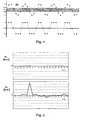
- the sine eigenvector with corresponding nodes is represented in the form of real numerical values. According to the above assignment rule, this sine eigenvector is shown in the lower representation of Fig. 1 converted course shown.
- the vector numerical values sin ( ⁇ ni / N) and cos ( ⁇ ni / N) in equations (2) are replaced by -1, 0 and 1, respectively.
- no multiplications are required to calculate the quantities s n and c n necessary, but essentially only additions required.
- the components of the eigenvectors in the form of the vector approximation values can each be stored in memories with 2-bit resolution, which reduces the memory requirements compared to the example discussed above by a factor of 4.
- the above-mentioned approximate vector numerical values for the fuzzy Fourier transformation can on the one hand be stored in a table which describes these trigonometric function approximations.
- the points can be calculated with little computational effort, in which the values of the functions are changed on the basis of the assignment rule described above. It takes place as a kind of "online calculation" of the fuzzy Fourier vector support points, which brings savings in computing capacity and energy requirements compared to the storage of precalculated support points.
- the amplitude coefficients C 1 , C 2 , C 3 , C 4 and the phase coefficients ⁇ 1 , ⁇ ' 1 , ⁇ 2 and ⁇ ' 2 are freely selectable.
- Fig. 3 the two spectral components s n and c n and the frequency-dependent amplitude A calculated with the aid of the formula (5) are shown.
- the results with the approximation method according to the invention are shown in solid lines, those of the discrete Fourier transform as dotted lines.
- Fig. 4 Based on Fig. 4 the evaluation results are shown using the inventive approximation method in a concrete practical example. This is how the top diagram in Fig. 4 a section of the measurement of the RR intervals, as they were determined from an ECG signal by sampling during a sampling interval of 1.25 sec. As can be seen, the period lengths of the RR intervals vary between approximately 970 and 1130 ms.
Landscapes
- Health & Medical Sciences (AREA)
- Life Sciences & Earth Sciences (AREA)
- Cardiology (AREA)
- Engineering & Computer Science (AREA)
- Physics & Mathematics (AREA)
- Biomedical Technology (AREA)
- Medical Informatics (AREA)
- Veterinary Medicine (AREA)
- Public Health (AREA)
- General Health & Medical Sciences (AREA)
- Biophysics (AREA)
- Pathology (AREA)
- Animal Behavior & Ethology (AREA)
- Heart & Thoracic Surgery (AREA)
- Physiology (AREA)
- Molecular Biology (AREA)
- Surgery (AREA)
- Signal Processing (AREA)
- Artificial Intelligence (AREA)
- Computer Vision & Pattern Recognition (AREA)
- Psychiatry (AREA)
- Mathematical Physics (AREA)
- Electrotherapy Devices (AREA)
- Measurement And Recording Of Electrical Phenomena And Electrical Characteristics Of The Living Body (AREA)
- Measuring Pulse, Heart Rate, Blood Pressure Or Blood Flow (AREA)
Description
- Die Erfindung betrifft ein Verfahren zur Berechnung der Herzratenvariabilität des menschlichen Herzens zur Anwendung in einem EKG-Monitor sowie einen EKG-Monitor, dessen Betriebsprogramm ein solches Berechnungsverfahren implementiert. Unter "EKG-Monitor" soll dabei jedwedes externes oder implantierbares Gerät verstanden werden, das EKG-Signale detektiert und auswertet, also neben den eigentlichen Monitoren z. B. auch die entsprechenden funktionalen Komponenten in Herzschrittmachern und Defibrillatoren.
- Zum Hintergrund der Erfindung ist auszuführen, daß die Herzratenvariabilität ein in der klinischen Praxis etablierter Risikoindikator bei Post-Infarkt-Patienten ist. Es ist daher ein erklärtes Ziel der Kardiologie, die Herzratenvariabilität bei solchen Post-Infarkt-Patienten aufzuzeichnen und auszuwerten, um im Falle alarmierender Werte geeignete Schritte einleiten zu können.
- Ein anderer Aspekt im Zusammenhang mit der vorliegenden Erfindung ist die herrschende Tendenz, kardiologische Überwachungsgeräte für herzkranke Patienten so zu konzipieren, daß das Gerät in den Körper des Patienten implantierbar ist.
- Bei der Bestimmung der Herzratenvariabilität wird nun das Frequenzspektrum der Herzrate bestimmt und die Verhältnisse der auftretenden Maxima ausgewertet. Das Frequenzspektrum wird dabei üblicherweise mit Hilfe der sogenannten "Fourier-Transformation" analysiert, indem das vom EKG-Monitor empfangene EKG-Signal während eines bestimmten Abtastintervalls abgetastet und daraus eine Reihe diskreter, für die Herzratenvariabilität repräsentativer Meßwerte, wie z. B. die RR-Intervalle, ermittelt werden. Ein solches Verfahren ist z. B, in der Patentschrift
US 5,967,995 offenbart. - Wie im Zuge der Beschreibung des Ausführungsbeispiels unter Bezugnahme auf entsprechende Formeln noch detaillierter dargelegt wird, wird das Frequenzspektrum der Meßwerte aus den Fourier-Koeffizienten der Fourier-Transformation berechnet. Die Fourier-Koeffizienten wiederum werden aus einer Kombination der Meßwerte mit den sinus- und kosinusförmigen Fourier-Vektoren der Fourier-Transformation berechnet.
- Problematisch bei der üblichen Fourier-Transformation ist die Tatsache, daß zur rechnerischen Implementierung die (kontinuierlichen) Fourier-Vektoren in diskrete Stützstellen übergeführt werden müssen. Die Stützstellen sind reelle Zahlen, die den sinus- und kosinusförmigen Verlauf der Fourier-Vektoren wiedergeben. In Abhängigkeit von der gewählten Anzahl von Stützstellen steigt nun die Anzahl der Multiplikationen, die zum Errechnen der Fourier-Koeffizienten aus den Fourier-Vektoren und den Meßwerten erforderlich sind, übeipropoitional an. Entsprechend erfordert die hohe Anzahl an Multiplikationsvorgängen mit reellen Zahlen einen extremen Rechenaufwand und einen enorm hohen Bedarf an Speicherkapazität. Ein Beispiel für die Fourier-Transfonnation ist in der Patenschrift
WO 86/02250 - Der hohe Rechen- und Speicheraufwand übersteigt die Kapazität von für kardiologische Geräteimplantate verfügbaren Mikroprozessorsystemen und deren Energieversorgung bei weitem, so daß die Anwendung einer Fourier-Transformation zur Frequenzanalyse mit den derzeit gängigen Berechnungsverfahren und Prozessorsystemen nicht möglich ist.
- Zur Lösung dieser Problematik schlägt nun die Erfindung vor, die bekannte (Fast-)Fourier-Transformation bei der Analyse der Herzratenvariabilität durch ein Näherungsverfahren zu ersetzen, das auf der Basis der Fourier-Transformation die Vektor-Zahlenwerte für die Berechnung des Frequenzspektrum der abgetasteten Meßwerte durch Vektor-Näherungswerte einer begrenzten Anzahl ersetzt, wobei die Vektor-Näherungswerte den Verlauf der Fourier-Vektoren nachbilden. Durch diese Maßnahme wird eine deutlich Verringerung des Rechen- und Speicher-Aufwandes erzielt, was die Anwendung in Geräte-Implantaten ermöglicht. Die Vereinfachung wird dadurch erreicht, daß die Fourier-Vektoren nicht mehr durch Stützstellen der Sinus- und Kosinusfunktionen in Form reeller Zahlen dargestellt werden. Statt dessen werden die Stützstellen als, ganzzahlige Vektor-Näherungsweite auf der Basis der Zahlen -1, 0 und +1 gewählt. Zusammenfassend wird durch diese "Vergröberung" der Stützstellen eine Art "Fuzzy-Fourier-Transformation" geschaffen.
- Günstige Auswerteergebnisse haben sich ergeben, wenn die Umsetzung der reellen Vektor-Zahlenwerte in die Näherungswerte -1, 0 und +1 mit einer Grenze von +/-0,33 erfolgt. Für einen Vektorzahlenwert zwischen -0,33 und +0,33 wird der Näherungswert zu 0 gesetzt, für Vektorzahlenwerte > +0,33 bzw. < -0,33 werden die Näherungswerte zu +1 bzw. -1 gesetzt.
- Da bei der herkömmlichen Fourier-Transformation die Summe der Vektor-Näherungswerte für jeden Fourier-Vektor einen Wert von 0 ergibt, kann bei einer Abweichung der Summe der Vektor-Näherungswerte vom Wert 0 mindestens ein Näherungswert so korrigiert werden, daß der Summenwert 0 beträgt. Damit wird ein scheinbarer Offset in dem analysierten Frequenzspektrum bzw. ein falscher Peak im berechneten Frequenzspektrum bei niedrigen Frequenzen vermieden.
- Die Erfindung bezieht sich ferner auf einen EKG-Monitor mit einem Betriebsprogramm, das das vorstehend erörterte Berechnungsverfahren implementiert. Dadurch wird der EKG-Monitor in den menschlichen Körper implantierbar bzw. kann in einen Herzschrittmacher integriert werden.
- Im folgenden wird das erfindungsgemäße Berechnungsverfahren anhand eines Ausführungsbeispiels unter Bezugnahme auf die beigefügten Zeichnungen näher erläutert. Es zeigen:
- Fig. 1
- ein Vergleichsdiagramm des Sinus-Eigenvektors der Fourier- Transformation und dessen Nachbildung durch ganzzahlige Vektor- Näherungswerte,
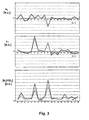
- Fig. 2
- eine Darstellung der mittels des Fuzzy-Fourier-Transformations- Näherungsverfahrens berechneten Spektralkomponenten eines ein- zelnen Sinussignals,
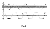
- Fig. 3
- eine Darstellung der entsprechend berechneten Spektralkomponen- ten und frequenzabhängigen Amplituden für eine Mischung von zwei Sinussignalen und einem Rauschsignal,
- Fig. 4
- Diagramme eines RR-Intervallverlaufs aus einem EKG-Abschnitt und der mit dem Fuzzy-Fourier-Transformations-Näherungs- verfahren berechneten Spektralkomponenten sowie Frequenzanaly- se, und
- Fig. 5
- ein Diagramm analog
Fig. 1 mit korrigierten Vektor- Näherungswerten. - Zum besseren Verständnis der Erfindung wird eingangs dieser Beschreibung kurz das Berechnungsprinzip der Fourier-Transformation rekapituliert. So besagen die Fourierschen Theoreme, daß sich eine Serie von Meßwerten Ri (i=0 ... 2N-1) beschreiben läßt als

- Die Spektralkomponenten sn und cn sind definiert durch

- Die Fourier-Koeffizienten ergeben sich also aus einer Linearkombination des Meßwertvektors
R und der sinus- bzw. kosinusförmigen Fourier-Vektorensinn bzw.cosn . Diese Fourier-Vektoren

- Für die Amplitude A einer Frequenz-Komponente f gilt nun bei einem Abtastintervall von Δt:

- Würde das vorstehende Gleichungssystem durch ein Steuerprogramm in einem EKG-Monitor implementiert werden, so wären bei einem Wert von N=16 im Gleichungssystem (2) für diese diskrete Fourier-Transformation bereits 1024 Multiplikationen erforderlich. Für die Eigenvektoren bei 8-Bit-Auflösung und 32 Eigenvektoren mit 32 Komponenten würde sich ein Speicherbedarf von 1 kByte ergeben. Diese Anforderungen machen eine Realisierung im Implantat unmöglich.
- Die erfindungsgemäße Fuzzy-Fourier-Transformation ist nun anhand von
Fig. 1 zu erläutern. Demnach werden die Vektor-Zahlenweite für die Fourier-Vektoren gemäß den Formeln (3) durch ganzzahlige Vektor-Näherungswerte, nämlich die drei Werte -1, 0 und +1 ersetzt. Die Zuordnungsvorschrift lautet wie folgt: - -0,33 < Vektor-Zahlenwert < +0,33: Näherungswert = 0
- Vektor-Zahlenwert < -0,33: Näherungswert = -1
- Vektor-Zahlenwert > +0,33: Näherungswert = +1
-
Fig. 1 zeigt diese Näherung für die Größen 2N=32, n=4. Im oberen Bereich ist der Sinus-Eigenvektor mit entsprechenden Stützstellen in Form reeller Zahlenwerte dargestellt. Nach der obigen Zuordnungsvorschrift wird dieser Sinus-Eigenvektor in den in der unteren Darstellung vonFig. 1 gezeigten Verlauf übergeführt. Es werden also die Vektor-Zahlenwerte sin(πni/N) und cos(πni/N) in den Gleichungen (2) ersetzt durch -1, 0 bzw. 1. Damit sind zur Berechnung der Größen sn und cn keine Multiplikationen mehr nötig, sondern im wesentlichen nur noch Additionen erforderlich. Zudem können die Komponenten der Eigenvektoren in Form der Vektor-Näherungswerte jeweils in Speichern mit 2-Bit-Auflösung abgespeichert werden, was den benötigen Speicheraufwand gegenüber dem oben erörterten Beispiel um einen Faktor 4 reduziert. - Die oben erwähnten genäherten Vektor-Zahlenwerte für die Fuzzy-Fourier-Transformation können einerseits in einer Tabelle abgespeichert werden, die diese trigonometrischen Funktionsnäherungen beschreibt. Alternativ dazu können auch die Punkte mit geringem Rechenaufwand berechnet werden, bei denen auf der Basis der oben bezeichneten Zuordnungsvorschrift die Werte der Funktionen geändert werden. Es findet als eine Art "Online-Berechnung" der Fuzzy-Fourier-Vektorstützstellen statt, was Einsparungen an Rechenkapazität und Energiebedarf gegenüber der Speicherung vorberechneter Stützstellen bringt.
- So gilt für den Näherungswert = +1 folgende Gleichung:


- Der Näherungswert 0 ergibt sich für

- Der Näherungswert -1 ergibt sich für

- Analog ergibt sich die Berechnung der Kosinus-Näherungswerte zum
- Näherungswert = +1, wenn ni > 0 +/- 2N und < als 0,393 N +/- 2N oder > 1,6070 N +/- 2N und < 2N +/- 2N
- Näherungswert -1, wenn ni zwischen 0,6070 N +/- 2N und 1,3930 N +/- 2N liegt sowie
- Näherungswert 0, wenn ni außerhalb der oben stehenden Wertebereiche liegt.
- Als weitere Vereinfachung läßt sich schließlich die Gleichung (4) ersetzen durch

- In einem Simulationsversuch wurde die vorstehend in ihrer Basis dargestellte Fuzzy-Fourier-Transformation angewendet und entsprechende Spektralkomponenten sn und cn berechnet und mit der diskreten Fourier-Transformation mit exakten Werten verglichen. Als Eingangssignal Ri wurde dabei folgendes Signal herangezogen, bei dem es sich um eine Summe von zwei Sinussignalen, einem Rauschsignal ("Random") und einem Offset handelt:

- Die Amplitudenkoëffizienten C1, C2, C3, C4 und die Phasenkoeffizienten δϕ1, ϕ'1, δϕ2 und ϕ'2 sind frei wählbar.
- Als Simulationsversuch wurde ein einzelnes Sinussignal mit δϕ1=5π/19 und ϕ1'=π/4 berechnet. Die Amplitudenkoeffizienten C2, C3 und C4 wurden zu 0 gesetzt.
- Die diskrete Fourier-Transformation ergibt nur einen einzelnen diskreten Peak im cn-Verlauf bei n=5, da die Phasenverschiebung von π/4 ein Kosinussignal zugrundelegt. In
Fig. 2 ist dieser Peak nicht eigens dargestellt. - Eine Anwendung des Fuzzy-Fourier-Transfoimations-Nähemngsverfahrens ergibt die in
Fig. 2 gezeigten Verläufe der Spektralkomponenten sn und cn. Daraus ist unmittelbar erkennbar, daß auch das Näherungsverfahren den Peak bei n=5 in der Spektralkomponente cn reproduziert, was für die Richtigkeit des Näherungsverfahrens ein Beleg ist. Allerdings sind die Basislinien von sn und cn nicht konstant gleich 0 und schwanken um diesen Wert. Es werden bis zu 20 % des maximalen Amplitudenwertes erreicht, was allerdings verkraftbar ist. - Eine komplexere Simulation mit dem oben angegebenen Eingangssignal ist im Ergebnis in
Fig. 3 dargestellt. Dabei wurde eine Mischung von zwei verrauschten Sinussignalen mit folgenden Parametern zugrundegelegt:
- In
Fig. 3 sind die beiden Spektralkomponenten sn und cn sowie die mit Hilfe der Formel (5) berechnete frequenzabhängige Amplitude A dargestellt. Die Ergebnisse mit dem erfindungsgemäßen Näherungsverfahren sind dabei mit durchgezogenen, die der diskreten Fourier-Transformation mit punktierten Linien aufgetragen. - Vergleicht man die beiden Signalverläufe in den einzelnen Diagrammteilen mit einander, so ist erkennbar, daß die Resultate der diskreten und der Fuzzy-Fourier-Transformation einander sehr ähnlich und das Näherungsverfahren damit brauchbar ist. Lediglich die Basislinie der frequenzabhängigen Amplitude A(f) im untersten Teil der
Fig. 3 wurde durch den Rauschanteil angehoben. Obwohl jedoch das Rauschsignal doppelt so groß wie die zwei Sinussignale sind, ist die Existenz dieser beiden Signale im Frequenzspektrum bei n=5 und n=9 erkennbar. - Anhand von
Fig. 4 sind die Auswerteergebnisse mit Hilfe des erfindunggemäßen Näherungsverfahrens in einem konkreten praktischen Beispiel dargestellt. So zeigt das oberste Diagramm inFig. 4 einen Ausschnitt der Messung der RR-Intervalle, wie sie aus einem EKG-Signal durch Abtastung während eines Abtastinterveralls von 1,25 sec. ermittelt wurden. Erkennbar schwanken die Periodendauern der RR-Intervalle zwischen ca. 970 und 1130 ms. - Bei Anwendung der diskreten Fourier-Transformation und des vorstehenden Näherungsverfahrens ergeben sich für beide Berechnungsarten Maxima bei n=3 und n=14, wie dem unteren Diagramm der
Fig. 4 entnehmbar ist. Diese beiden Maxima liegen bei Umrechnung in den Frequenzraum bei Werten von 0,075 Hz und 0,35 Hz. - Bei Durchführung des Näherungsverfahrens wurde im übrigen festgestellt, daß die bei der diskreten Fourier-Transformation geltende Bedingung, daß die Summe der Komponenten eines einzelnen Eigenvektors (mit Ausnahme des Vektors
cos0 ) gleich 0 ist, bei einigen Annäherungen der Kosinus-Eigenvektoren nicht erfüllt ist. Es ergab sich eine Summe von -2 oder 2, wie dies beispielsweise bei den im unteren Diagramm vonFig. 5 durch eine strichlierte Linie unterlegten Vektor-Näherungswerten der Fall ist. Dies würde sich in einem starken niederfrequenten Peak im berechneten Frequenzspektrum äußern. Zu dessen Vermeidung werden die Vektor-Näherungswerte so korrigiert, daß der Summenwert 0 beträgt. In dem inFig. 5 gezeigten Beispiel werden zwei Näherungswerte mit dem Wert 0 auf den Wert +1 angehoben, wie dies durch die beiden Pfeile angedeutet ist. Durch diese Korrektur beträgt die Summe der Vektor-Näherungswerte 0. - Abschließend ist darauf hinzuweisen, daß die Vektorlänge 2N einen wesentlichen Einfluß auf die Genauigkeit der Fuzzy-Fourier-Transformation hat. Läßt sich die Länge N in eine Mehrzahl kleinerer Vektoren von gleicher Länge 1 verteilen, so daß gilt N=n•1 und es treten bei der Umsetzung der Eigenvektoren gleiche Annäherungen mehrfach auf. Dies kann bei bestimmten Frequenzen deutliche Nebenmaxima bis zu 30 % im berechneten Frequenzspektrum A(f) erzeugen. Optimal ist daher eine Vektorlänge, bei der die Länge N einer Primzahl entspricht, d. h.

- In den vorstehend beschriebenen Beispielen betrug der Wert von 2N=2•19=38.
- In den anhängenden Tabellen 1 und 2 sind schließlich geeignete Vektor-Näherungswerte für die Eigenvektor sinn,i und cosn,i aufgezeigt.
- Näherungen für sinn,i
Tabelle 1 i n 0 1 2 3 4 5 6 7 8 9 10 11 12 13 14 15 16 17 18 0 0 0 0 0 0 0 0 0 0 0 0 0 0 0 0 0 0 0 0 1 0 0 0 1 1 1 1 1 1 1 1 1 1 1 1 1 1 0 0 2 0 0 1 1 1 1 1 1 1 0 0 -1 -1 -1 -1 -1 -1 -1 0 3 0 1 1 1 1 1 0 0 -1 -1 -1 -1 0 0 1 1 1 1 1 4 0 1 1 1 1 0 -1 -1 -1 0 0 1 1 1 0 -1 -1 -1 -1 5 0 1 1 1 0 -1 -1 -1 0 1 1 0 -1 -1 -1 0 1 1 1 6 0 1 1 0 -1 -1 0 1 1 1 -1 -1 -1 0 1 1 0 -1 -1 7 0 1 1 0 -1 -1 1 1 0 -1 -1 0 1 1 -1 -1 0 1 1 8 0 1 1 -1 -1 0 1 0 -1 -1 1 1 0 -1 0 1 1 -1 -1 9 0 1 0 -1 0 1 1 -1 -1 1 1 -1 -1 1 1 0 -1 0 1 10 0 1 0 -1 0 1 -1 -1 1 1 -1 -1 1 1 -1 0 1 0 -1 11 0 1 -1 -1 1 0 -1 0 1 -1 -1 1 0 -1 0 1 -1 -1 1 12 0 1 -1 0 1 -1 -1 1 0 -1 1 0 -1 1 1 -1 0 1 -1 13 0 1 -1 0 1 -1 0 1 -1 1 1 -1 1 0 -1 1 0 -1 1 14 0 1 -1 1 0 -1 1 -1 0 1 -1 0 1 -1 1 0 -1 1 -1 15 0 1 -1 1 -1 0 1 -1 1 0 0 1 -1 1 0 -1 1 -1 1 16 0 1 -1 1 -1 1 0 0 1 -1 1 -1 0 0 -1 1 -1 1 -1 17 0 0 -1 1 -1 1 -1 1 -1 0 0 -1 1 -1 1 -1 1 -1 0 18 0 0 0 1 -1 1 -1 1 -1 1 -1 1 -1 1 -1 1 -1 0 0 19 0 0 0 0 0 0 0 0 0 0 0 0 0 0 0 0 0 0 0 20 0 0 0 -1 1 -1 1 -1 1 -1 1 -1 1 -1 1 -1 1 0 0 21 0 0 1 -1 1 -1 1 -1 1 0 0 1 -1 1 -1 1 -1 1 0 22 0 -1 1 -1 1 -1 0 0 -1 1 -1 1 0 0 1 -1 1 -1 1 23 0 -1 1 -1 1 0 -1 1 -1 0 0 -1 1 -1 0 1 -1 1 -1 24 0 -1 1 -1 0 1 -1 1 0 -1 1 0 -1 1 -1 0 1 -1 1 25 0 -1 1 0 -1 1 0 -1 1 -1 -1 1 -1 0 1 -1 0 1 -1 26 0 -1 1 0 -1 1 1 -1 0 1 -1 0 1 -1 -1 1 0 -1 1 27 0 -1 1 1 -1 0 1 0 -1 1 1 -1 0 1 0 -1 1 1 -1 28 0 -1 0 1 0 -1 1 1 -1 -1 1 1 -1 -1 1 0 -1 0 1 29 0 -1 0 1 0 -1 -1 1 1 -1 -1 1 1 -1 -1 0 1 0 -1 30 0 -1 -1 1 1 0 -1 0 1 1 -1 -1 0 1 0 -1 -1 1 1 31 0 -1 -1 0 1 1 -1 -1 0 1 1 0 -1 -1 1 1 0 -1 -1 32 0 -1 -1 0 1 1 0 -1 -1 -1 1 1 1 0 -1 -1 0 1 1 33 0 -1 -1 -1 0 1 1 1 0 -1 -1 0 1 1 1 0 -1 -1 -1 34 0 -1 -1 -1 -1 0 1 1 1 0 0 -1 -1 -1 0 1 1 1 1 35 0 -1 -1 -1 -1 -1 0 0 1 1 1 1 0 0 -1 -1 -1 -1 -1 36 0 0 -1 -1 -1 -1 -1 -1 -1 0 0 1 1 1 1 1 1 0 37 0 0 0 -1 -1 1 -1 -1 -1 -1 -1 -1 -1 -1 -1 -1 -1 0 0 - Näherungen für cosn,i
Tabelle 2 i n 0 1 2 3 4 5 6 7 8 9 10 11 12 13 14 15 16 17 18 0 1 1 1 1 1 1 1 1 1 1 1 1 1 1 1 1 1 1 1 1 1 1 1 1 1 1 1 1 0 0 0 0 0 -1 -1 -1 -1 -1 0 2 1 1 1 1 0 0 -1 -1 -1 -1 -1 -1 -1 -1 0 0 1 1 1 3 1 1 1 0 0 -1 -1 -1 -1 0 0 1 1 1 1 1 0 -1 -1 4 1 1 0 -1 -1 -1 -1 0 1 1 1 1 0 -1 -1 -1 -1 0 1 5 1 1 0 -1 -1 -1 0 1 1 1 -1 -1 -1 0 1 1 1 0 -1 6 1 1 -1 -1 -1 0 1 1 0 -1 -1 0 1 1 0 -1 0 -1 1 7 1 1 -1 -1 0 1 1 0 -1 -1 1 1 0 -1 -1 0 1 1 -1 8 1 0 -1 -1 1 1 0 -1 0 1 1 -1 -1 0 1 1 -1 -1 0 9 1 0 -1 0 1 1 -1 -1 1 1 -1 -1 1 1 -1 -1 0 1 0 10 1 0 -1 0 1 -1 -1 1 1 -1 0 1 1 -1 0 1 0 -1 0 11 1 0 -1 1 1 -1 0 1 -1 -1 1 1 -1 0 1 -1 -1 1 0 12 1 -1 -1 1 0 -1 1 0 -1 1 1 -1 0 1 -1 0 1 -1 -1 13 1 -1 0 1 -1 0 1 -1 0 1 -1 0 1 -1 0 1 -1 1 1 14 1 -1 0 1 -1 1 0 -1 1 -1 -1 1 -1 0 1 -1 1 0 -1 15 1 -1 0 1 -1 1 -1 0 1 -1 1 -1 0 1 -1 1 -1 0 1 16 1 -1 1 0 -1 1 -1 1 -1 0 0 -1 1 -1 1 -1 0 1 -1 17 1 -1 1 -1 0 0 0 1 -1 1 -1 1 -1 1 0 0 1 -1 1 18 1 -1 1 -1 1 -1 1 -1 0 0 0 0 -1 1 -1 1 -1 1 -1 19 1 -1 1 -1 1 -1 1 -1 1 -1 1 -1 1 -1 1 -1 1 -1 1 20 1 -1 1 -1 1 -1 1 -1 0 0 0 0 0 1 -1 1 -1 1 0 21 1 -1 1 -1 0 0 -1 1 -1 1 -1 1 -1 1 0 0 1 -1 1 22 1 -1 1 0 0 1 -1 1 -1 0 0 -1 1 -1 1 -1 0 1 -1 23 1 -1 0 1 -1 1 -1 0 1 -1 1 -1 0 1 -1 1 -1 0 1 24 1 -1 0 1 -1 1 0 -1 1 -1 -1 1 -1 0 1 -1 1 0 -1 25 1 -1 -1 1 -1 0 1 -1 0 1 -1 0 1 -1 0 1 0 1 1 26 1 -1 -1 1 0 -1 1 0 -1 1 1 -1 0 1 -1 0 1 -1 -1 27 1 0 -1 1 1 -1 0 1 0 -1 1 1 -1 0 1 -1 -1 1 0 28 1 0 -1 0 1 -1 -1 1 1 -1 -1 1 1 -1 -1 1 0 -1 0 29 1 0 -1 0 1 1 -1 -1 1 1 0 -1 1 1 0 -1 0 1 0 30 1 0 -1 -1 1 1 0 -1 -1 1 1 -1 -1 0 1 1 -1 -1 0 31 1 1 -1 -1 0 1 1 0 -1 -1 1 1 0 -1 -1 0 1 1 -1 32 1 1 0 -1 -1 0 1 1 0 -1 -1 0 1 1 0 -1 -1 -1 1 33 1 1 0 -1 -1 -1 0 1 1 1 -1 -1 -1 0 1 1 1 0 -1 34 1 1 0 -1 -1 -1 -1 0 1 1 1 1 0 -1 -1 -1 -1 0 1 35 1 1 1 0 -1 -1 -1 -1 -1 0 0 1 1 1 1 1 0 -1 -1 36 1 1 1 1 0 0 0 -1 -1 -1 -1 -1 -1 -1 0 0 1 1 1 37 1 1 1 1 1 1 1 1 0 0 0 0 -1 -1 -1 -1 -1 -1 -1
Claims (7)
- Verfahren zur Berechnung der Herzratenvariabilität des menschlichen Herzens durch Auswertung des Frequenzspektrums der Herzrate zur Anwendung in einem EKG-Monitor mit folgenden Verfahrensschritten:- Abtasten des vom EKG-Monitor empfangenen EKG-Signals während eines Abtastintervalls,- Ermittlung einer Reihe diskreter, für die Herzratenvariabilität repräsentativer Meßwerte aus den abgetasteten EKG-Signalen, und- Bestimmen der Herzatenvariabilität durch Auswerten dieser Meßwerte auf der Basis der Fourier-Transformation, wobei das Frequenzspektrum der Meßwerte aus den Fourier-Koeffizienten der Fourier-Transformation berechnet wird, und wobei die Fourier-Koeffizienten wiederum aus einer Kombination der Meßwerte mit den sinus- und kosinusförmigen Fourier-Vektoren der Fourier-Transformation berechnet werden, wobei die Fourier-Vektoren jeweils in Form einer Reihe diskreter Vektor-Zahlenwerte in die Berechnung einbezogen werden,
gekennzeichnet durch folgende Verfahrensschritte:- Ersetzen der Vektor-Zahlenwerte der Fourier-Vektoren für die Berechnung des Frequenzspektrums der abgetasteten Meßwerte durch ganzzahlige Vektor-Näherungswerte mit den Werten -1, 0 und + 1, wobei die Vektor-Näherungswerte in Abhängigkeit des tatsächlichen Vektor-Zahlenwertes wie folgt gesetzt werden:- -0,33 < Vektor-Zahlenwert < +0,33: Vektor-Näherungswert = 0- Vektor-Zahlenwert < -0,33: Vektor-Nähemngswert = -1- Vektor-Zahlenwert > +0,33: Vektor-Näherungswert = + 1.- Verwendung der ganzzahligen Vektor-Näherungswerte anstelle der sinus- und kosinusförmigen Feurier-Vektoren für die Berechnung des Frequenzspektrums - Verfahren nach Anspruch 1, dadurch gekennzeichnet, daß die Zuordnung der Näherungswerte zu den tatsächlichen Vektor-Zahlenwerten tabellarisch gespeichert im EKG-Monitor abgelegt sind.
- Verfahren nach Anspruch 1, dadurch gekennzeichnet, daß die Zuordnung der Näherungswerte durch Berechnung der Punkte erfolgt, bei denen sich die Vektor-Näherungswerte ändern.
- Verfahren nach einem der Ansprüche 1 bis 3, dadurch gekennzeichnet, daß die Summe der Vektor-Näherungswerte für jeden Fourier-Vektor gebildet und im Falle einer Abweichung vom Wert 0 mindestens ein Näherungswert korrigiert wird, bis der Summenwert 0 beträgt.
- EKG-Monitor mit einem Betriebsprogramm dadurch gekennzeichnet, daß das Betriebsprogramm ein Berechnungsverfahren nach einem der Ansprüche 1 bis 4 implementiert.
- EKG-Monitor nach Anspruch 5, dadurch gekennzeichnet, daß er in den menschlichen Körper implantierbar ist.
- EKG-Monitor nach Anspruch 5 oder 6, dadurch gekennzeichnet, daß er in einen Herzschrittmacher integriert ist.
Applications Claiming Priority (2)
| Application Number | Priority Date | Filing Date | Title |
|---|---|---|---|
| DE10006154 | 2000-02-11 | ||
| DE10006154A DE10006154A1 (de) | 2000-02-11 | 2000-02-11 | Verfahren zur Berechnung der Herzratenvariabilität zur Anwendung in einem EKG-Monitor sowie EKG-Monitor mit einem entsprechenden Berechnungsprogramm |
Publications (3)
| Publication Number | Publication Date |
|---|---|
| EP1124186A2 EP1124186A2 (de) | 2001-08-16 |
| EP1124186A3 EP1124186A3 (de) | 2009-12-02 |
| EP1124186B1 true EP1124186B1 (de) | 2012-01-11 |
Family
ID=7630621
Family Applications (1)
| Application Number | Title | Priority Date | Filing Date |
|---|---|---|---|
| EP01101489A Expired - Lifetime EP1124186B1 (de) | 2000-02-11 | 2001-01-24 | Verfahren zur Berechnung der Herzratenvariabilität zur Anwendung in einem EKG-Monitor sowie EKG-Monitor mit einem entsprechenden Berechnungsprogramm |
Country Status (4)
| Country | Link |
|---|---|
| US (1) | US6532382B2 (de) |
| EP (1) | EP1124186B1 (de) |
| AT (1) | ATE541261T1 (de) |
| DE (1) | DE10006154A1 (de) |
Families Citing this family (12)
| Publication number | Priority date | Publication date | Assignee | Title |
|---|---|---|---|---|
| DE10329606B4 (de) * | 2003-06-30 | 2008-07-03 | Zentrum Mikroelektronik Dresden Ag | Anordnung zur Frequenzbereichstransformation von Signalen |
| CA2560294C (en) * | 2004-03-18 | 2014-05-27 | Helicor Inc. | Methods and devices for relieving stress |
| US8002711B2 (en) * | 2005-03-18 | 2011-08-23 | Respironics, Inc. | Methods and devices for relieving stress |
| US8504143B2 (en) | 2008-12-15 | 2013-08-06 | Vitalcare Medical Ltd. | Method and system for measuring heart rate variability |
| EP2316333A1 (de) | 2009-10-28 | 2011-05-04 | Eidgenössische Materialprüfungs- und Forschungsanstalt EMPA | Vorrichtung und Verfahren zum Erkennen und Melden eines Belastungszustandes einer Person |
| WO2014047032A1 (en) * | 2012-09-18 | 2014-03-27 | Worcester Polytechnic Institute | Fabrication and use of epidermal electrodes |
| EP2721999A1 (de) | 2012-10-16 | 2014-04-23 | xotoxtools ag | Vorrichtung und Verfahren zum Erkennen und Melden eines Belastungszustandes einer Person |
| CN104887215B (zh) * | 2015-06-12 | 2017-11-03 | 上海新微技术研发中心有限公司 | 一种心率测量中的信号处理方法 |
| CN106383808B (zh) * | 2016-09-18 | 2019-08-02 | 时瑞科技(深圳)有限公司 | 心率心电信号的处理系统及方法 |
| US12161442B2 (en) | 2020-09-18 | 2024-12-10 | Covidien Lp | Method for producing an augmented physiological signal based on a measurement of activity |
| DE102021212454A1 (de) | 2021-11-04 | 2023-05-04 | Fraunhofer-Gesellschaft zur Förderung der angewandten Forschung eingetragener Verein | Verfahren zum trainieren und/oder ausführen eines faltungsbasierten neuronalen netzes mittels einer approximierten schnellen fourier-transformation |
| DE102021212453B4 (de) | 2021-11-04 | 2025-02-20 | Fraunhofer-Gesellschaft zur Förderung der angewandten Forschung eingetragener Verein | Verfahren zur approximativen berechnung von schmetterlingseinheiten einer fourier-transformation eines signales |
Family Cites Families (8)
| Publication number | Priority date | Publication date | Assignee | Title |
|---|---|---|---|---|
| DE2659090A1 (de) * | 1976-12-27 | 1978-07-06 | Siemens Ag | Bahnsteuereinrichtung bei einer von einem rechner gefuehrten steuerung einer numerisch gesteuerten werkzeugmaschine |
| CA1244135A (en) * | 1984-10-15 | 1988-11-01 | Harold M Hastings | EXTERNAL FETAL HEART MONITOR |
| EP0448196B1 (de) * | 1990-03-19 | 1997-03-12 | Del Mar Avionics | Verfahren und Gerät zur Spektralanalyse von elektrokardiographischen Signalen |
| US5330504A (en) * | 1992-03-16 | 1994-07-19 | Telectronics Pacing Systems, Inc. | Cardioverting defibrillating device with off-line ECG analysis |
| GB9518094D0 (en) * | 1995-09-05 | 1995-11-08 | Cardionics Ltd | Heart monitoring apparatus |
| US5772604A (en) * | 1997-03-14 | 1998-06-30 | Emory University | Method, system and apparatus for determining prognosis in atrial fibrillation |
| US5827195A (en) * | 1997-05-09 | 1998-10-27 | Cambridge Heart, Inc. | Electrocardiogram noise reduction using multi-dimensional filtering |
| US5967995A (en) * | 1998-04-28 | 1999-10-19 | University Of Pittsburgh Of The Commonwealth System Of Higher Education | System for prediction of life-threatening cardiac arrhythmias |
-
2000
- 2000-02-11 DE DE10006154A patent/DE10006154A1/de not_active Withdrawn
-
2001
- 2001-01-24 AT AT01101489T patent/ATE541261T1/de active
- 2001-01-24 EP EP01101489A patent/EP1124186B1/de not_active Expired - Lifetime
- 2001-02-12 US US09/780,366 patent/US6532382B2/en not_active Expired - Lifetime
Also Published As
| Publication number | Publication date |
|---|---|
| US20010016694A1 (en) | 2001-08-23 |
| EP1124186A2 (de) | 2001-08-16 |
| US6532382B2 (en) | 2003-03-11 |
| EP1124186A3 (de) | 2009-12-02 |
| DE10006154A1 (de) | 2001-08-16 |
| ATE541261T1 (de) | 2012-01-15 |
Similar Documents
| Publication | Publication Date | Title |
|---|---|---|
| DE2811463C2 (de) | Elektrischer Anreger für Menschenmuskeln mit bioelektrischer Steuerung | |
| DE69433456T2 (de) | Vorrichtung zum Klassifizieren von Herzrhythmen basierend auf der Morphologie des Elektrogramms | |
| DE69726447T2 (de) | Implantierbares medizinisches gerät mit beschleunigungssensor | |
| DE69415909T2 (de) | Dynamischer Filter zur Echtzeit-Entfernung parasitärer Signale aus Wellenformen | |
| EP0576509B1 (de) | Medizinisches gerät zur erzeugung einer behandlungsgrösse | |
| DE3620220A1 (de) | Mit begrenzung des ausgangssignals arbeitender elektrischer stimulator fuer biologisches gewebe | |
| DE10246404B4 (de) | Verfahren und System zur Messung von T-Wellen-Alternationen | |
| EP1124186A2 (de) | Verfahren zur Berechnung der Herzratenvariabilität zur Anwendung in einem EKG-Monitor sowie EKG-Monitor mit einem entsprechenden Berechnungsprogramm | |
| EP0401265B1 (de) | Verfahren zur anpassung der stimulationsfrequenz eines herzschrittmachers an die belastung eines patienten | |
| DE1940833B2 (de) | Herzschlagmessgeraet | |
| DE2344211C2 (de) | Elektromagnetischer Blut-Strömungsmesser | |
| EP1140285B1 (de) | Herzschrittmacher | |
| EP1262143B1 (de) | Verfahren und Speichervorrichtung zur Speicherung von Herzrhythmusinformation | |
| EP0883372A1 (de) | Verfahren und vorrichtung zur messung des intracraniellen druckes in einem schädel eines probanden | |
| EP2338566B1 (de) | Implantierbares medizinisches Gerät mit Mitteln zur Rekonstruktion eines unvollständig erfassten Signals | |
| DE102006039957A1 (de) | Verfahren zur Auswertung der Herzratenvariabilität | |
| DE19958735A1 (de) | Betriebsverfahren für ein kardiologisches Geräteimplantat, insbesondere einen Herzschrittmacher | |
| DE112019003630B4 (de) | Biosensoreinrichtung | |
| EP0847776A1 (de) | Vorrichtung zum Stimulieren eines Muskels oder von Muskelgruppen | |
| EP0793979A2 (de) | Anordnung zur Bestimmung der Herzrate | |
| DE69934794T2 (de) | Herzschrittmacher mit messung der stimulationsschwelle | |
| DE2516167A1 (de) | Verfahren und vorrichtung zur quantitativen bestimmung des auftretens von verzoegerungen beim foetalen herzschlag | |
| EP0573684B1 (de) | Verfahren und Vorrichtung zum Ermitteln eines physiologischen Funktionsparameters eines Lebewesens | |
| EP1048000B1 (de) | Erweiterte kardiogoniometrie | |
| EP2067439A1 (de) | Verfahren zum Bestimmen einer muskulären Ermüdung |
Legal Events
| Date | Code | Title | Description |
|---|---|---|---|
| PUAI | Public reference made under article 153(3) epc to a published international application that has entered the european phase |
Free format text: ORIGINAL CODE: 0009012 |
|
| AK | Designated contracting states |
Kind code of ref document: A2 Designated state(s): AT BE CH CY DE DK ES FI FR GB GR IE IT LI LU MC NL PT SE TR |
|
| AX | Request for extension of the european patent |
Free format text: AL;LT;LV;MK;RO;SI |
|
| RAP1 | Party data changed (applicant data changed or rights of an application transferred) |
Owner name: BIOTRONIK GMBH & CO. KG |
|
| PUAL | Search report despatched |
Free format text: ORIGINAL CODE: 0009013 |
|
| AK | Designated contracting states |
Kind code of ref document: A3 Designated state(s): AT BE CH CY DE DK ES FI FR GB GR IE IT LI LU MC NL PT SE TR |
|
| AX | Request for extension of the european patent |
Extension state: AL LT LV MK RO SI |
|
| RIC1 | Information provided on ipc code assigned before grant |
Ipc: A61N 1/365 20060101ALN20091027BHEP Ipc: G01R 23/16 20060101ALI20091027BHEP Ipc: A61B 5/0245 20060101ALI20091027BHEP Ipc: G06F 17/00 20060101AFI20010515BHEP |
|
| 17P | Request for examination filed |
Effective date: 20100201 |
|
| 17Q | First examination report despatched |
Effective date: 20100323 |
|
| AKX | Designation fees paid |
Designated state(s): AT BE CH CY DE DK ES FI FR GB GR IE IT LI LU MC NL PT SE TR |
|
| RAP1 | Party data changed (applicant data changed or rights of an application transferred) |
Owner name: BIOTRONIK SE & CO. KG |
|
| RAP1 | Party data changed (applicant data changed or rights of an application transferred) |
Owner name: BIOTRONIK SE & CO. KG |
|
| GRAP | Despatch of communication of intention to grant a patent |
Free format text: ORIGINAL CODE: EPIDOSNIGR1 |
|
| GRAS | Grant fee paid |
Free format text: ORIGINAL CODE: EPIDOSNIGR3 |
|
| GRAA | (expected) grant |
Free format text: ORIGINAL CODE: 0009210 |
|
| AK | Designated contracting states |
Kind code of ref document: B1 Designated state(s): AT BE CH CY DE DK ES FI FR GB GR IE IT LI LU MC NL PT SE TR |
|
| REG | Reference to a national code |
Ref country code: GB Ref legal event code: FG4D Free format text: NOT ENGLISH |
|
| REG | Reference to a national code |
Ref country code: CH Ref legal event code: EP |
|
| REG | Reference to a national code |
Ref country code: AT Ref legal event code: REF Ref document number: 541261 Country of ref document: AT Kind code of ref document: T Effective date: 20120115 |
|
| REG | Reference to a national code |
Ref country code: IE Ref legal event code: FG4D |
|
| REG | Reference to a national code |
Ref country code: DE Ref legal event code: R096 Ref document number: 50116031 Country of ref document: DE Effective date: 20120308 |
|
| REG | Reference to a national code |
Ref country code: SE Ref legal event code: TRGR |
|
| REG | Reference to a national code |
Ref country code: NL Ref legal event code: VDEP Effective date: 20120111 |
|
| BERE | Be: lapsed |
Owner name: BIOTRONIK SE & CO. K.G. Effective date: 20120131 |
|
| PG25 | Lapsed in a contracting state [announced via postgrant information from national office to epo] |
Ref country code: NL Free format text: LAPSE BECAUSE OF FAILURE TO SUBMIT A TRANSLATION OF THE DESCRIPTION OR TO PAY THE FEE WITHIN THE PRESCRIBED TIME-LIMIT Effective date: 20120111 |
|
| PG25 | Lapsed in a contracting state [announced via postgrant information from national office to epo] |
Ref country code: PT Free format text: LAPSE BECAUSE OF FAILURE TO SUBMIT A TRANSLATION OF THE DESCRIPTION OR TO PAY THE FEE WITHIN THE PRESCRIBED TIME-LIMIT Effective date: 20120511 Ref country code: FI Free format text: LAPSE BECAUSE OF FAILURE TO SUBMIT A TRANSLATION OF THE DESCRIPTION OR TO PAY THE FEE WITHIN THE PRESCRIBED TIME-LIMIT Effective date: 20120111 Ref country code: GR Free format text: LAPSE BECAUSE OF FAILURE TO SUBMIT A TRANSLATION OF THE DESCRIPTION OR TO PAY THE FEE WITHIN THE PRESCRIBED TIME-LIMIT Effective date: 20120412 Ref country code: MC Free format text: LAPSE BECAUSE OF NON-PAYMENT OF DUE FEES Effective date: 20120131 |
|
| PG25 | Lapsed in a contracting state [announced via postgrant information from national office to epo] |
Ref country code: CY Free format text: LAPSE BECAUSE OF FAILURE TO SUBMIT A TRANSLATION OF THE DESCRIPTION OR TO PAY THE FEE WITHIN THE PRESCRIBED TIME-LIMIT Effective date: 20120111 |
|
| PG25 | Lapsed in a contracting state [announced via postgrant information from national office to epo] |
Ref country code: DK Free format text: LAPSE BECAUSE OF FAILURE TO SUBMIT A TRANSLATION OF THE DESCRIPTION OR TO PAY THE FEE WITHIN THE PRESCRIBED TIME-LIMIT Effective date: 20120111 |
|
| PLBE | No opposition filed within time limit |
Free format text: ORIGINAL CODE: 0009261 |
|
| STAA | Information on the status of an ep patent application or granted ep patent |
Free format text: STATUS: NO OPPOSITION FILED WITHIN TIME LIMIT |
|
| PG25 | Lapsed in a contracting state [announced via postgrant information from national office to epo] |
Ref country code: IT Free format text: LAPSE BECAUSE OF FAILURE TO SUBMIT A TRANSLATION OF THE DESCRIPTION OR TO PAY THE FEE WITHIN THE PRESCRIBED TIME-LIMIT Effective date: 20120111 |
|
| 26N | No opposition filed |
Effective date: 20121012 |
|
| PG25 | Lapsed in a contracting state [announced via postgrant information from national office to epo] |
Ref country code: BE Free format text: LAPSE BECAUSE OF NON-PAYMENT OF DUE FEES Effective date: 20120131 |
|
| REG | Reference to a national code |
Ref country code: DE Ref legal event code: R097 Ref document number: 50116031 Country of ref document: DE Effective date: 20121012 |
|
| REG | Reference to a national code |
Ref country code: AT Ref legal event code: MM01 Ref document number: 541261 Country of ref document: AT Kind code of ref document: T Effective date: 20120124 |
|
| PG25 | Lapsed in a contracting state [announced via postgrant information from national office to epo] |
Ref country code: ES Free format text: LAPSE BECAUSE OF FAILURE TO SUBMIT A TRANSLATION OF THE DESCRIPTION OR TO PAY THE FEE WITHIN THE PRESCRIBED TIME-LIMIT Effective date: 20120422 |
|
| PGFP | Annual fee paid to national office [announced via postgrant information from national office to epo] |
Ref country code: GB Payment date: 20130122 Year of fee payment: 13 Ref country code: SE Payment date: 20130122 Year of fee payment: 13 Ref country code: FR Payment date: 20130207 Year of fee payment: 13 |
|
| PG25 | Lapsed in a contracting state [announced via postgrant information from national office to epo] |
Ref country code: AT Free format text: LAPSE BECAUSE OF NON-PAYMENT OF DUE FEES Effective date: 20120124 |
|
| PG25 | Lapsed in a contracting state [announced via postgrant information from national office to epo] |
Ref country code: TR Free format text: LAPSE BECAUSE OF FAILURE TO SUBMIT A TRANSLATION OF THE DESCRIPTION OR TO PAY THE FEE WITHIN THE PRESCRIBED TIME-LIMIT Effective date: 20120111 |
|
| PG25 | Lapsed in a contracting state [announced via postgrant information from national office to epo] |
Ref country code: LU Free format text: LAPSE BECAUSE OF NON-PAYMENT OF DUE FEES Effective date: 20120124 |
|
| REG | Reference to a national code |
Ref country code: SE Ref legal event code: EUG |
|
| GBPC | Gb: european patent ceased through non-payment of renewal fee |
Effective date: 20140124 |
|
| REG | Reference to a national code |
Ref country code: FR Ref legal event code: ST Effective date: 20140930 |
|
| PG25 | Lapsed in a contracting state [announced via postgrant information from national office to epo] |
Ref country code: FR Free format text: LAPSE BECAUSE OF NON-PAYMENT OF DUE FEES Effective date: 20140131 Ref country code: GB Free format text: LAPSE BECAUSE OF NON-PAYMENT OF DUE FEES Effective date: 20140124 Ref country code: SE Free format text: LAPSE BECAUSE OF NON-PAYMENT OF DUE FEES Effective date: 20140125 |
|
| REG | Reference to a national code |
Ref country code: DE Ref legal event code: R082 Ref document number: 50116031 Country of ref document: DE Representative=s name: RANDOLL, SOEREN, DIPL.-CHEM. UNIV. DR. RER. NA, DE |
|
| PGFP | Annual fee paid to national office [announced via postgrant information from national office to epo] |
Ref country code: DE Payment date: 20160119 Year of fee payment: 16 |
|
| PGFP | Annual fee paid to national office [announced via postgrant information from national office to epo] |
Ref country code: CH Payment date: 20170125 Year of fee payment: 17 |
|
| PGFP | Annual fee paid to national office [announced via postgrant information from national office to epo] |
Ref country code: IE Payment date: 20170123 Year of fee payment: 17 |
|
| REG | Reference to a national code |
Ref country code: DE Ref legal event code: R119 Ref document number: 50116031 Country of ref document: DE |
|
| PG25 | Lapsed in a contracting state [announced via postgrant information from national office to epo] |
Ref country code: DE Free format text: LAPSE BECAUSE OF NON-PAYMENT OF DUE FEES Effective date: 20170801 |
|
| REG | Reference to a national code |
Ref country code: CH Ref legal event code: PL |
|
| REG | Reference to a national code |
Ref country code: IE Ref legal event code: MM4A |
|
| PG25 | Lapsed in a contracting state [announced via postgrant information from national office to epo] |
Ref country code: CH Free format text: LAPSE BECAUSE OF NON-PAYMENT OF DUE FEES Effective date: 20180131 Ref country code: LI Free format text: LAPSE BECAUSE OF NON-PAYMENT OF DUE FEES Effective date: 20180131 |
|
| PG25 | Lapsed in a contracting state [announced via postgrant information from national office to epo] |
Ref country code: IE Free format text: LAPSE BECAUSE OF NON-PAYMENT OF DUE FEES Effective date: 20180124 |