EP1124107B1 - Endkammer für Wärmetauscherkern - Google Patents
Endkammer für Wärmetauscherkern Download PDFInfo
- Publication number
- EP1124107B1 EP1124107B1 EP01301110A EP01301110A EP1124107B1 EP 1124107 B1 EP1124107 B1 EP 1124107B1 EP 01301110 A EP01301110 A EP 01301110A EP 01301110 A EP01301110 A EP 01301110A EP 1124107 B1 EP1124107 B1 EP 1124107B1
- Authority
- EP
- European Patent Office
- Prior art keywords
- header
- welded
- plate
- heat exchanger
- cut
- Prior art date
- Legal status (The legal status is an assumption and is not a legal conclusion. Google has not performed a legal analysis and makes no representation as to the accuracy of the status listed.)
- Expired - Lifetime
Links
Images


Classifications
-
- F—MECHANICAL ENGINEERING; LIGHTING; HEATING; WEAPONS; BLASTING
- F28—HEAT EXCHANGE IN GENERAL
- F28F—DETAILS OF HEAT-EXCHANGE AND HEAT-TRANSFER APPARATUS, OF GENERAL APPLICATION
- F28F9/00—Casings; Header boxes; Auxiliary supports for elements; Auxiliary members within casings
- F28F9/02—Header boxes; End plates
-
- F—MECHANICAL ENGINEERING; LIGHTING; HEATING; WEAPONS; BLASTING
- F28—HEAT EXCHANGE IN GENERAL
- F28D—HEAT-EXCHANGE APPARATUS, NOT PROVIDED FOR IN ANOTHER SUBCLASS, IN WHICH THE HEAT-EXCHANGE MEDIA DO NOT COME INTO DIRECT CONTACT
- F28D9/00—Heat-exchange apparatus having stationary plate-like or laminated conduit assemblies for both heat-exchange media, the media being in contact with different sides of a conduit wall
- F28D9/0062—Heat-exchange apparatus having stationary plate-like or laminated conduit assemblies for both heat-exchange media, the media being in contact with different sides of a conduit wall the conduits for one heat-exchange medium being formed by spaced plates with inserted elements
-
- F—MECHANICAL ENGINEERING; LIGHTING; HEATING; WEAPONS; BLASTING
- F28—HEAT EXCHANGE IN GENERAL
- F28D—HEAT-EXCHANGE APPARATUS, NOT PROVIDED FOR IN ANOTHER SUBCLASS, IN WHICH THE HEAT-EXCHANGE MEDIA DO NOT COME INTO DIRECT CONTACT
- F28D21/00—Heat-exchange apparatus not covered by any of the groups F28D1/00 - F28D20/00
- F28D2021/0019—Other heat exchangers for particular applications; Heat exchange systems not otherwise provided for
- F28D2021/0033—Other heat exchangers for particular applications; Heat exchange systems not otherwise provided for for cryogenic applications
-
- Y—GENERAL TAGGING OF NEW TECHNOLOGICAL DEVELOPMENTS; GENERAL TAGGING OF CROSS-SECTIONAL TECHNOLOGIES SPANNING OVER SEVERAL SECTIONS OF THE IPC; TECHNICAL SUBJECTS COVERED BY FORMER USPC CROSS-REFERENCE ART COLLECTIONS [XRACs] AND DIGESTS
- Y10—TECHNICAL SUBJECTS COVERED BY FORMER USPC
- Y10T—TECHNICAL SUBJECTS COVERED BY FORMER US CLASSIFICATION
- Y10T29/00—Metal working
- Y10T29/49—Method of mechanical manufacture
- Y10T29/4935—Heat exchanger or boiler making
- Y10T29/49389—Header or manifold making
Definitions
- the present invention relates to a plate-fin type heat exchanger, and more specifically, to the technical field of a large plate-fin type heat exchanger capable of being used at high pressure.
- Plate-fin type heat exchangers are used to exchange the heat of a fluid in, for example, the processing of natural gases and in cryogenic service.
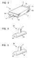
- the plate-fin type heat exchanger is typically constructed as shown Fig. 3 which is an overall perspective view of it and from Figs. 4 and 5 which are perspective views of a header of it.
- Fig. 4 shows an orange-peel-shaped (petal-shaped) welded-type header of the plate-fin type heat exchanger
- Fig. 5 shows a pressed-type header of the plate-fin type heat exchanger.
- a typical plate-fin type heat exchanger 1 includes a core 2 for carrying out heat exchange.
- the core 2 is constructed such that the upper and lower apexes of plate-fins (not shown), which are formed in a wave shape, are brazed to the confronting surfaces of partitions (not shown) and the openings of the partitions at both the ends thereof in a width direction are closed with side bars (not shown).
- a header 3 having a nozzle 4, to which various pipes are to be connected at the extreme end thereof, is welded to each end of the core 2 in a lengthwise direction to supply fluid into and out of the core 2.
- a plate-fin type heat exchanger for processing a multiplicity of fluids various types of constructions are employed as necessary, although not shown, such as a combination of a plurality of laminated cores, a core having headers mounted on the ends thereof in a width direction in addition to a lengthwise direction, and the like.
- the nozzle is not always welded to the header but may be welded to necessary portions in accordance with a method for processing a fluid.
- headers as shown in Figs. 4 and 5 are conventionally employed as the header 3 of the plate-fin type heat exchanger. That is, a header according to a conventional example 1 shown in Fig. 4 is an orange-peel-welded-type header 3w that is composed of a trough-shaped plate main body 31 having a nozzle 4 welded to the apex thereof and end plates 32 welded to both the openings of the trough-shaped plate main body 31 in a lengthwise direction (at four positions at the corners thereof). Further, a header according to a conventional example 2 shown in Fig. 5 is a pressed-type header 3p and is composed of a trough-shaped plate main body 31 and end plates 32 that are molded integrally by a press.
- the pressure resistance, reliability, and cost efficiency of the header 3p are superior to those of the header 3w.
- One reason the pressed-type header 3p is superior to the welded-type header 3w in the pressure resistance and reliability is that it does not have any welded portion, and one reason it is superior to the welded-type header 3w in cost efficiency is that it can be produced in volume by the same press mold.
- the pressed-type header of the conventional example 2 shown in Fig. 5 cannot be employed in a large plate-fin type heat exchanger because the length of it is restricted by the capacity of existing presses. That is, the pressed header, which is superior to the welded header in pressure resistance, cannot be employed in the larger plate-fin type heat exchanger that is used at high pressure, and actually, the welded-type header cannot help being employed in the large plate-fin type heat exchanger regardless of whether it is inferior to the pressed-type header in cost performance.
- US 4,274,481 discloses a header for a heat exchanger used in a dry cooling tower. There is no disclosure of the precise structure of the header or any indication of high pressure applications.
- EP 0 676 608 discloses a heat-exchanger having a header.
- the header consists of a U-shaped middle piece and two end pieces.
- the invention described therein provides an adaptable header so that the middle piece and the end pieces may be made in a standard construction.
- the inventors have completed this invention by finding that a longer large header, which is superior to a welded-type header in pressure resistance, can be easily manufactured by cutting off a plurality of pressed-type headers according to the conventional example 2 of Fig. 5, which have been molded by an existing press, in a direction perpendicular to a longitudinal direction and by welding the cut-off portions thereof to the cut-off portion of the necessary portions of another pressed-type header having been cut off because a tensile force mainly acts on the welded portions. Further, the number of welded portions of the thus obtained longer large header can be reduced as compared with that of the welded-type header according to the conventional example 1 shown in Fig.
- the cut-off portions can be easily welded because they are welded in a circumferential direction (the welding in the circumferential direction can be performed more easily that the welding of the end plates of the conventional example 1).
- a plate-fin type heat exchanger (1) comprising:
- the present invention also provides a method for manufacturing a plate-fin type heat exchanger (1), said heat exchanger (1), comprising: a core (2) having a plate-fin and side bars interposed between partitions; and a header (3) welded to said core, said header including a pair of ends (3c) that are formed by cutting off press-shaped headers in a direction perpendicular to a longitudinal direction, and wherein the method includes the step of constructing said header by welding said pair of ends (3c) to both the ends of a trough-shaped plate (3b).
- FIG. 1A is a perspective view of a header thereof
- Fig. 1B which is a view explaining how a pressed-type header molded by an existing press is cut off
- Fig. 3 which is a plan view of a header manufactured by welding the pressed-type headers having been cut off to each other.
- the components of the embodiment which are the same as those of the conventional examples or which have the same functions as those of the conventional examples, will be described with reference to the same numerals denoted thereby.
- only the construction of the header will be described here because the embodiment 1 is different from the above conventional examples only in the construction of the header.
- Numeral 3 in Figs. 1A and 1C denotes a header which is constructed such that one-side-cut-off headers 3a, each of which has an end plate 32 at one end of a trough-shaped plate main body 31 and has no end plate 32 at the other thereof, are welded to each other through the ends thereof and a nozzle 4 is welded to the position of the welded portion 5 of the one-side-cut-off headers 3a.
- the header 3 of the plate-fin type heat exchanger according to the embodiment 1 is manufactured such that two sets of pressed-shape headers 3p are molded by the existing press, one end sides of the respective pressed-type headers 3p are cut off in directions which are parallel with each other and are perpendicular to the upper surfaces thereof, on which the nozzle 4 is welded, and to the lower end surfaces thereof in a lengthwise direction as shown in Fig. 1B, and the two sets of the longer one-side-cut-off headers 3a that are obtained by being cut off are used as the header 3.
- the header 3 of the plate-fin type heat exchanger according to the embodiment 1 is manufactured by welding the two sets of the one-side-cut-off headers 3a, which have been obtained by cutting off one end sides of the pressed-shape headers 3p molded by the existing press, to each other. Accordingly, the size of the header 3 can be very easily increased. Moreover, the header 3 is superior to the welded-type header 3w in pressure resistance because it has such a construction that tensile strength is mainly applied to the welded portion 5 as is understood well by a comparison of Fig. 4 showing the welded-type header 3w according to the conventional example 1 with Figs. 1A to 1C according to the embodiment. Thus, a large plate-fin type heat exchanger that can be used at high pressure can be manufactured by the employment of the header 3.
- the number of welded portions of the header 3 can be reduced more than that of the welded-type header according to the conventional example shown in Fig. 4 (the number of the welded portions can be reduced to one position as compared with four positions in the conventional example 1), whereby the header 3 can be easily welded because it is welded in a circumferential direction (the circumferential welding is easier than the welding of the end plates of the conventional example 1). Further, it is sufficient to weld the nozzle 4 to the header 3 only when it is necessary. When the nozzle 4 is welded as necessary, the selection of the welded portion 5 as the welding position thereof as shown in Figs. 1A to 1C can achieve a cost reducing effect because the length of the welded portion 5, which must be inspected using radiation is shortened thereby and man-hours necessary for the test can be reduced accordingly, in addition to the above effect.
- the length of the shorter cut-off portion obtained by cutting off the pressed-type header 3p molded by the existing press is very short as compared with the overall length of the pressed-shape header 3p. Therefore, according to the embodiment 1, a large header 3 which is almost twice as long as the overall length of the pressed-type header 3p molded by the existing press can be easily obtained.
- FIG. 2A is a perspective view of a header thereof
- Fig. 2B which is a view explaining how a pressed-type header molded by an existing press is cut off
- Fig. 2C which is a plan view of a header manufactured by welding pressed-type headers having been cut off to each other.
- the components of the embodiment which are the same as those of the embodiment 1 or which have the same functions as those of the embodiment 1, will be described with reference to the same numerals denoted thereby.
- only the header will be described here because the embodiment 2 is different from the embodiment 1 only in the construction of the header.
- Numeral 3 shown in Fig. 2A denotes the header which is constructed from a both-side-cut-off-header 3b composed only of a trough-shaped plate main body 31 having a nozzle 4 welded to the apex thereof and having no end plate 32 on both the sides thereof and trough-shaped plate main bodies 31, each of which is composed of a portion thereof and an end plate 32 that are molded integrally with each other, abutted against and welded to the ends of the both-side-cut-off-header 3b. That is, the header is manufactured such that two sets of pressed-type headers 3p are molded by the existing press, one of them is cut off at both ends thereof, and the other is cut off at the center thereof as shown in Fig.
- the header 3 is manufactured by the both-side-cut-off trough-shaped header 3b which is obtained by cutting off the pressed-type header 3p at both ends thereof and the two sets of the pressed-type half-cut headers 3c that are obtained by cutting off the pressed-type header 3p at the center thereof.
- the nozzle 4 is welded to the header 3 in Figs. 2A to 2C, it is welded as necessary and is not essential, similarly tc the embodiment 1.
- the overall length of the header 3 can be optionally adjusted to a necessary size by appropriately changing the length of the pressed-type half-cut headers 3c by further cutting off the cut-off end sides thereof as necessary, and the adjustable range of the overall length of the header 3 is similar to that of the embodiment 1.
- both-side-cut-off header 3b which is obtained by cutting off the pressed-type header 3p at both the ends thereof, is used in the embodiment 2, a plate member and a pipe member may be utilized in place of the both-side-cut-off header 3b.
- the header 3 according to the embodiment 2 is manufactured by cutting off the two sets of the pressed-type headers 3p molded by the existing press and welding the thus obtained both-side-cut-off headers 3b to the two sets of the half-cut headers 3c obtained by the cutting-off, similarly to the header according to the embodiment 1, which results in advantages that the number of welded portions is reduced as compared with the number of them of the welded-type header according to the conventional example shown in Fig. 4 (which can be reduced to two positions as compared with four positions in the conventional for example 1) and that the header 3b can be easily welded to the header 3c because they are welded in a circumferential direction (the circumferential welding can be carried out more easily than the welding of the end plates of the conventional example 1).
- the length of the welded portions 5 of the header 3 according to the embodiment 3 is shorter than that of the conventional example 1.
- the embodiment 2 is disadvantageous as compared with the embodiment 1 as to the welding cost of the abutted portions and the cost of an inspection by radiation applied to the welded portions 5.
- the embodiment 2 can obtain the following advantages that cannot be obtained by the embodiment 1.
- the header 3 according to the embodiment 2 has such an advantage that the both-side-cut-off header 3b at the central portion, which is obtained by cutting off both the ends of the press-shaped header 3p to which the nozzle 4 is welded, has an appropriate length and many construction members such as various kinds of plate members and pipe members can be combined therewith beforehand, which permits the header 3 to be designed cost-effectively.
- the wall thickness of the both-side-cut-off header 3b can be easily changed from that of the half-cut headers 3c which are welded to the header 3b.
- the wall thickness of the header 3 must be increased in the vicinity of the nozzle 4 to secure the area of the opening of the nozzle 4.
- the wall thickness of the both-side-cut-off header 3b which is located at the central portion and is disadvantageous in strength due to the nozzle 4 welded thereto, can be increased, and thus there can be obtained an effect that the reliability of the vicinity of the portion where the nozzle 4 is welded can be increased.
- the plate-fin type heat exchanger can be manufactured by the combination of the embodiments 1 and 2. That is, the plate-fin type heat exchanger can be manufactured as described below.
- a plurality of headers must be made.
- one header 5 is manufactured as described in the embodiment 1.
- two short portions which are made by cutting off the pressed-type header 3p, remain.
- another header 3 is manufactured as shown in the embodiment 2, wherein the two short portions that are cut off by cutting the pressed-type header 3p are utilized as two end components which are to be welded to both the cut ends of the trough-shaped plate main body 31 (as the half-cut press-shaped headers 3c in the example shown in Fig. 2).
- the two short portions that remain in the manufacture of one header 3 can be utilized to manufacture another header 3, by which waste and costs can be cut.
- a long pipe member for example, is utilized in the trough-shaped plate main body 31 of the another header 3 to secure the length of the header 3.
- no pressed-type header 3p is necessary to manufacture the another header 3, which is cost effective as compared with the header of Fig. 2 which requires two sets of pressed-type headers 3p.
- a header of a plate-fin type heat exchanger is molded by an existing press, and the cut-off portions of a pair of press-shaped headers one end side of each of which in a longitudinal direction is cut off are utilized as end portions.
- the cut-off portions of a pair of pressed-type headers may be directly welded to each other so that the pressed-type headers are molded integrally with each other. Otherwise, a nozzle may be welded to a welded portion where the cut-off portions of the pair of pressed-type headers are welded to each other.
- the size of the header can be very easily increased, and further, a tensile force mainly acts on the welded portion, different from the welded portion of the welded-type header of the conventional example 1, and thus the header of the present invention is superior to the welded-type header in pressure resistance, which permits a large plate-fin type heat exchanger that can be used at high pressure to be easily manufactured.
- the number of the welded portions of the plate-fin type heat exchanger of the present invention can be reduced as compared with that of the welded-type header according to the conventional example 1 (the number can be reduced to one position as compared with four positions of the conventional example 1). Further, the plate-fin type heat exchanger of the present invention can be easily welded because it is welded in a circumferential direction (the circumferential welding can be more easily carried out than the welding of the end plates of the conventional example 1). In addition to the above, since the man-hours necessary to test the welded portions using radiation wave can be reduced, a cost reduction effect can be achieved by the reduction of a cost necessary to test the welded portions.
- a header of a plate-fin type heat exchanger may be constructed integrally such that the cut-off portions of a press-shaped header molded by an existing press are welded to the respective ends of a trough-shaped plate main body formed in a mountain-like shape, and further, a nozzle may be welded to the trough-shaped plate main body.
- the plate-fin type heat exchanger of the present invention has such an advantage that many construction members such as various types of plate members and pipe members can be combined beforehand with the central portion of the heat exchanger that is obtained by cutting off both the ends of the press-shaped header because the central portion has an appropriate length in advance and the head can be designed cost effectively, in addition to the above-mentioned advantages.
- the wall thickness of the central portion that is obtained by cutting off both the ends of the press-shaped header can easily be changed from that of other press-shaped headers to be welded to the ends of the central portion so that the wall thickness of the central portion which is made disadvantageous in strength by the nozzle welded thereto can be increased, by which an advantage can be obtained in that the plate members and the pipe members can be utilized in place of a both-side-cut-off header, in addition to the advantage that the reliability of the vicinity of the portion where the nozzle is welded can be easily increased.
Landscapes
- Engineering & Computer Science (AREA)
- Physics & Mathematics (AREA)
- Thermal Sciences (AREA)
- Mechanical Engineering (AREA)
- General Engineering & Computer Science (AREA)
- Heat-Exchange Devices With Radiators And Conduit Assemblies (AREA)
- Separation By Low-Temperature Treatments (AREA)
Claims (4)
- Plattenrippenartiger Wärmetauscher (1), umfassend:einen Kern (2), der eine Plattenrippe bzw. -finne und Seitenstangen aufweist, die zwischen den Unterteilungen zwischengelagert sind; undeine Endkammer bzw. Kammer bzw. Kopf,(3), die mit dem Kern verschweißt ist, wobei die Endkammer (3) ein Paar von Enden (3a) aufweist, dadurch gekennzeichnet, daß die Enden (3a) durch ein Abschneiden von preßgeformten Endkammern (3p) des plattenrippenartigen Wärmetauschers in einer Richtung senkrecht zu einer Längsrichtung davon ausgebildet sind, und daßdie Endkammer (3) durch ein Verschweißen der abgeschnittenen Abschnitte des Paars von Enden (3a) miteinander konstruiert ist.
- Plattenrippenartiger Wärmetauscher nach Anspruch 1, weiterhin umfassend eine Düse (4), die mit der Endkammer (3) verschweißt ist und mit einem verschweißten Abschnitt (5) verschweißt ist, wo die abgeschnittenen Abschnitte des Paars von Enden (3a) miteinander verschweißt sind.
- Verfahren zum Herstellen eines plattenrippenartigen Wärmetauschers (1), wobei der Wärmetauscher (1) umfaßt: einen Kern (2), der eine Plattenrippe bzw. -finne und Seitenstangen aufweist, die zwischen Unterteilungen zwischengelagert werden; und eine Endkammer (3), die mit dem Kern verschweißt wird, wobei die Endkammer (3) ein Paar von Enden (3c) beinhaltet, dadurch gekennzeichnet, daß das Verfahren den Schritt eines Ausbildens der Enden (3c) durch ein Abschneiden von preßgeformten Endkammern (3p) des plattenrippenartigen Wärmetauschers in einer Richtung senkrecht zu einer Längsrichtung davon, und
den Schritt eines Konstruierens der Endkammer (3) durch ein Verschweißen der Paare von Enden (3c) mit beiden Enden einer trogförmigen Platte (3b) umfaßt. - Verfahren nach Anspruch 3, wobei der plattenrippenartige Wärmetauscher weiterhin eine Düse (4) umfaßt, die mit der trogförmigen Platte (3b) verschweißt wird.
Applications Claiming Priority (2)
| Application Number | Priority Date | Filing Date | Title |
|---|---|---|---|
| JP2000031727 | 2000-02-09 | ||
| JP2000031727A JP2001221582A (ja) | 2000-02-09 | 2000-02-09 | プレートフィン型熱交換器 |
Publications (3)
| Publication Number | Publication Date |
|---|---|
| EP1124107A2 EP1124107A2 (de) | 2001-08-16 |
| EP1124107A3 EP1124107A3 (de) | 2003-01-29 |
| EP1124107B1 true EP1124107B1 (de) | 2007-03-28 |
Family
ID=18556440
Family Applications (1)
| Application Number | Title | Priority Date | Filing Date |
|---|---|---|---|
| EP01301110A Expired - Lifetime EP1124107B1 (de) | 2000-02-09 | 2001-02-08 | Endkammer für Wärmetauscherkern |
Country Status (4)
| Country | Link |
|---|---|
| US (1) | US20010017200A1 (de) |
| EP (1) | EP1124107B1 (de) |
| JP (1) | JP2001221582A (de) |
| DE (1) | DE60127479T2 (de) |
Families Citing this family (9)
| Publication number | Priority date | Publication date | Assignee | Title |
|---|---|---|---|---|
| CN100453959C (zh) * | 2003-01-17 | 2009-01-21 | 西安交通大学 | 板翅式换热器流体分配封头 |
| KR100525424B1 (ko) * | 2003-09-18 | 2005-11-02 | 엘지전자 주식회사 | 열교환기용 냉매 분배기와 그 제조방법 |
| JP5295737B2 (ja) * | 2008-12-01 | 2013-09-18 | 住友精密工業株式会社 | プレートフィン型熱交換器 |
| PL2542373T3 (pl) * | 2010-03-02 | 2021-05-31 | Velocys, Inc. | Laminowany przyrząd lutowany na twardo, sposoby wytwarzania i stosowania przyrządu |
| CN101806554A (zh) * | 2010-03-31 | 2010-08-18 | 开封空分集团有限公司 | 板翅式换热器散布器 |
| DE102010025017B4 (de) * | 2010-06-24 | 2018-07-05 | Benteler Automobiltechnik Gmbh | Wärmetauscher |
| JP5982221B2 (ja) * | 2012-08-21 | 2016-08-31 | 株式会社神戸製鋼所 | プレートフィン熱交換器及びプレートフィン熱交換器の補修方法 |
| JP5764116B2 (ja) * | 2012-12-26 | 2015-08-12 | 住友精密工業株式会社 | 熱交換器 |
| EP3647706A1 (de) | 2018-11-02 | 2020-05-06 | HS Marston Aerospace Limited | Laminierte wärmetauscher |
Family Cites Families (5)
| Publication number | Priority date | Publication date | Assignee | Title |
|---|---|---|---|---|
| DE2302769C3 (de) * | 1973-01-20 | 1980-01-31 | Sueddeutsche Kuehlerfabrik Julius Fr. Behr Gmbh & Co Kg, 7000 Stuttgart | Rohrbündel-Wärmetauscher |
| US4274481A (en) * | 1979-10-22 | 1981-06-23 | Stewart-Warner Corporation | Dry cooling tower with water augmentation |
| FR2544250B1 (fr) * | 1983-04-12 | 1985-07-12 | Valeo | Procede et dispositif de fabrication par moulage d'une boite a eau d'un echangeur de chaleur, en particulier pour vehicule automobile, et boite a eau ainsi obtenue |
| JPH06147790A (ja) * | 1992-11-11 | 1994-05-27 | Showa Alum Corp | 熱交換器用ヘッダの製造方法 |
| SE501628C2 (sv) * | 1994-04-11 | 1995-04-03 | Valeo Engine Cooling Ab | Värmeväxlartank med ändstycken samt värmeväxlare försedd med densamma |
-
2000
- 2000-02-09 JP JP2000031727A patent/JP2001221582A/ja active Pending
-
2001
- 2001-02-07 US US09/778,086 patent/US20010017200A1/en not_active Abandoned
- 2001-02-08 EP EP01301110A patent/EP1124107B1/de not_active Expired - Lifetime
- 2001-02-08 DE DE60127479T patent/DE60127479T2/de not_active Expired - Lifetime
Also Published As
| Publication number | Publication date |
|---|---|
| US20010017200A1 (en) | 2001-08-30 |
| EP1124107A3 (de) | 2003-01-29 |
| EP1124107A2 (de) | 2001-08-16 |
| DE60127479T2 (de) | 2007-12-13 |
| DE60127479D1 (de) | 2007-05-10 |
| JP2001221582A (ja) | 2001-08-17 |
Similar Documents
| Publication | Publication Date | Title |
|---|---|---|
| US5423376A (en) | Heat exchanger for electronic components and electro-technical equipment | |
| EP1231448B1 (de) | Wärmetauscher | |
| US6412547B1 (en) | Heat exchanger and method of making the same | |
| US5348081A (en) | High capacity automotive condenser | |
| US7621317B2 (en) | Self-breaking radiator side plates | |
| US5797184A (en) | Method of making a heat exchanger | |
| US5052480A (en) | Pipe for coolant condenser | |
| EP1124107B1 (de) | Endkammer für Wärmetauscherkern | |
| JPH11226685A (ja) | 熱交換器およびヘッダタンクの製造方法 | |
| JP2007032949A (ja) | 熱交換器 | |
| JP2017180856A (ja) | 熱交換器 | |
| KR100336712B1 (ko) | 플레이트-핀 형 열교환기 및 그의 제조방법 | |
| KR100511380B1 (ko) | 험프형플레이트핀열교환기 | |
| JPS58164995A (ja) | 熱交換器及びその製造方法 | |
| CN116907262A (zh) | 换热组件和板翅式换热器 | |
| CN113192911A (zh) | 一种微通道散热器 | |
| JP2001174188A (ja) | サーペンタイン型熱交換器及びこれに用いられるチューブの製造方法 | |
| EP1626239A1 (de) | Wärmetauscher und zugehöriges Herstellungsverfahren | |
| JPH11230686A (ja) | 熱交換器 | |
| CN212457511U (zh) | 换热系统 | |
| EP0601209B1 (de) | Wärmetauscher mit maschigen kühlrippen sowie verfahren zu dessen herstellung | |
| CN220454380U (zh) | 换热组件和板翅式换热器 | |
| JP2005009828A (ja) | 熱交換器 | |
| US20220390187A1 (en) | Micro-channel heat exchanger | |
| JPH0711332Y2 (ja) | 熱交換器 |
Legal Events
| Date | Code | Title | Description |
|---|---|---|---|
| PUAI | Public reference made under article 153(3) epc to a published international application that has entered the european phase |
Free format text: ORIGINAL CODE: 0009012 |
|
| 17P | Request for examination filed |
Effective date: 20010228 |
|
| AK | Designated contracting states |
Kind code of ref document: A2 Designated state(s): AT BE CH CY DE DK ES FI FR GB GR IE IT LI LU MC NL PT SE TR |
|
| AX | Request for extension of the european patent |
Free format text: AL;LT;LV;MK;RO;SI |
|
| PUAL | Search report despatched |
Free format text: ORIGINAL CODE: 0009013 |
|
| AK | Designated contracting states |
Designated state(s): AT BE CH CY DE DK ES FI FR GB GR IE IT LI LU MC NL PT SE TR |
|
| AX | Request for extension of the european patent |
Extension state: AL LT LV MK RO SI |
|
| AKX | Designation fees paid |
Designated state(s): DE FR GB |
|
| 17Q | First examination report despatched |
Effective date: 20040910 |
|
| GRAP | Despatch of communication of intention to grant a patent |
Free format text: ORIGINAL CODE: EPIDOSNIGR1 |
|
| GRAS | Grant fee paid |
Free format text: ORIGINAL CODE: EPIDOSNIGR3 |
|
| GRAA | (expected) grant |
Free format text: ORIGINAL CODE: 0009210 |
|
| AK | Designated contracting states |
Kind code of ref document: B1 Designated state(s): DE FR GB |
|
| REG | Reference to a national code |
Ref country code: GB Ref legal event code: FG4D |
|
| REF | Corresponds to: |
Ref document number: 60127479 Country of ref document: DE Date of ref document: 20070510 Kind code of ref document: P |
|
| ET | Fr: translation filed | ||
| PLBE | No opposition filed within time limit |
Free format text: ORIGINAL CODE: 0009261 |
|
| STAA | Information on the status of an ep patent application or granted ep patent |
Free format text: STATUS: NO OPPOSITION FILED WITHIN TIME LIMIT |
|
| 26N | No opposition filed |
Effective date: 20080102 |
|
| REG | Reference to a national code |
Ref country code: FR Ref legal event code: PLFP Year of fee payment: 16 |
|
| REG | Reference to a national code |
Ref country code: FR Ref legal event code: PLFP Year of fee payment: 17 |
|
| REG | Reference to a national code |
Ref country code: FR Ref legal event code: PLFP Year of fee payment: 18 |
|
| PGFP | Annual fee paid to national office [announced via postgrant information from national office to epo] |
Ref country code: DE Payment date: 20200129 Year of fee payment: 20 Ref country code: GB Payment date: 20200129 Year of fee payment: 20 |
|
| PGFP | Annual fee paid to national office [announced via postgrant information from national office to epo] |
Ref country code: FR Payment date: 20200113 Year of fee payment: 20 |
|
| REG | Reference to a national code |
Ref country code: DE Ref legal event code: R071 Ref document number: 60127479 Country of ref document: DE |
|
| REG | Reference to a national code |
Ref country code: GB Ref legal event code: PE20 Expiry date: 20210207 |
|
| PG25 | Lapsed in a contracting state [announced via postgrant information from national office to epo] |
Ref country code: GB Free format text: LAPSE BECAUSE OF EXPIRATION OF PROTECTION Effective date: 20210207 |