EP1124093B1 - Flexible lance for working on or inspecting a tube plate of a steam generator - Google Patents
Flexible lance for working on or inspecting a tube plate of a steam generator Download PDFInfo
- Publication number
- EP1124093B1 EP1124093B1 EP01101967A EP01101967A EP1124093B1 EP 1124093 B1 EP1124093 B1 EP 1124093B1 EP 01101967 A EP01101967 A EP 01101967A EP 01101967 A EP01101967 A EP 01101967A EP 1124093 B1 EP1124093 B1 EP 1124093B1
- Authority
- EP
- European Patent Office
- Prior art keywords
- strip
- flexible lance
- band
- flexible
- tendon
- Prior art date
- Legal status (The legal status is an assumption and is not a legal conclusion. Google has not performed a legal analysis and makes no representation as to the accuracy of the status listed.)
- Expired - Lifetime
Links
Images


Classifications
-
- F—MECHANICAL ENGINEERING; LIGHTING; HEATING; WEAPONS; BLASTING
- F22—STEAM GENERATION
- F22B—METHODS OF STEAM GENERATION; STEAM BOILERS
- F22B37/00—Component parts or details of steam boilers
- F22B37/02—Component parts or details of steam boilers applicable to more than one kind or type of steam boiler
- F22B37/48—Devices for removing water, salt, or sludge from boilers; Arrangements of cleaning apparatus in boilers; Combinations thereof with boilers
- F22B37/483—Devices for removing water, salt, or sludge from boilers; Arrangements of cleaning apparatus in boilers; Combinations thereof with boilers specially adapted for nuclear steam generators
Abstract
Description
Die Erfindung bezieht sich auf eine flexible Lanze zum Bearbeiten oder Inspizieren eines Rohrbodens eines Dampferzeugers, mit einem flexiblen metallischen ersten Band und einer daran in Längsrichtung geführten Versorgungsleitung für einen am freien Ende des ersten Bands angeordneten Bearbeitungs- oder Inspektionskopf.The invention relates to a flexible lance for processing or inspecting a tube plate of a steam generator, having a flexible metallic first band and a longitudinally guided supply line for a processing or inspection head arranged at the free end of the first band.
Eine solche flexible Lanze ist z.B. in
In den Rohrböden von Dampferzeugern, insbesondere von nuklearen Dampferzeugern, verbleiben nach einer gewissen Betriebszeit festhaftende Verunreinigungen. Diese Verunreinigungen können an manchen Stellen eine Höhe von einigen Zentimetern aufweisen. Da die Verunreinigungen sehr hart sind, besteht die Gefahr einer Beschädigung der in engem Abstand angeordneten Dampferzeugerrohre (Denting).In the tubesheets of steam generators, in particular of nuclear steam generators remain after a certain period of time stuck impurities. These impurities can in some places have a height of a few centimeters. Since the impurities are very hard, there is a risk of damaging the closely spaced steam generator pipes (denting).
Bei Rohrböden von Dampferzeugern muss aus diesem Grund auf der Sekundärseite regelmäßig untersucht werden, ob und in welchem Ausmaß sich zwischen den Heizrohren Ablagerungen gebildet haben. Diese Ablagerungen müssen dann gegebenenfalls entfernt werden, um Schäden an den Heizrohren zu vermeiden.For tube sheets of steam generators, it is therefore necessary to regularly check on the secondary side whether and to what extent deposits have formed between the heating tubes. If necessary, these deposits must be removed to prevent damage to the heating pipes.
Dies geschieht für die festhaftenden Ablagerungen in erster Linie durch Spritzverfahren. Beispielsweise ist aus der Europäischen Patentschrift
Es hat sich jedoch gezeigt, dass damit festhaftende Ablagerungen im Innenbereich der Rohrbündel nicht vollständig entfernt werden können. Um eine effiziente Reinigung des Rohrbodens zu gewährleisten, ist es deshalb erforderlich, einen Spritzkopf unmittelbar in die Zwischenräume zwischen die Heizrohre zu führen und einen Hochdruck-Flüssigkeitsstrahl unmittelbar auf die Ablagerungen im Inneren der Heizrohrbündel zu richten.However, it has been shown that firmly adhering deposits in the interior of the tube bundle can not be completely removed. To ensure efficient cleaning of the tubesheet, it is therefore necessary to To direct the spray head directly into the spaces between the heating tubes and direct a high-pressure liquid jet directly to the deposits inside the heating tube bundle.
Zur Führung einer Versorgungsleitung für einen Inspektionskopf und/oder zur Führung einer Flüssigkeitsversorgungsleitung für das genannte Spritzverfahren ist aus
Der Erfindung liegt demzufolge die Aufgabe zugrunde, eine flexible Lanze anzugeben, die einfach herzustellen ist und bei der die Versorgungsleitung dennoch vor einer Beschädigung durch Abknicken der Lanze geschützt ist.The invention is therefore an object of the invention to provide a flexible lance that is easy to manufacture and in which the supply line is still protected from damage by bending the lance.
Diese Aufgabe wird bezogen auf die eingangs genannte flexible Lanze gemäß der Erfindung gelöst durch eine in Längsrichtung am ersten Band angeordnete erste Sehne, die eine höhere Biegesteifigkeit als das Band aufweist und wobei das erste Band einstückig ausgebildet ist.This object is achieved in relation to the above-mentioned flexible lance according to the invention by a longitudinally arranged on the first band first chord, which has a higher bending stiffness than the band and wherein the first band is integrally formed.
Unter einer Sehne wird in diesem Zusammenhang jedes, insbesondere reversibel oder elastisch, biegsame entlang der Längsrichtung ausgedehnte Versteifungselement verstanden. Mit der Sehne ist das Band in einfacher Weise versteifbar, ohne dass die Baugröße der Lanze dadurch ansteigen würde. Die Sehne, deren Durchmesser vorzugsweise den der Versorgungsleitung nicht übersteigt, kann nämlich seitlich neben der Versorgungsleitung geführt werden.In this context, a tendon means any, in particular reversible or elastic, flexible stiffening element extended along the longitudinal direction. With the string, the band is easily stiffened, without that the size of the lance would increase as a result. The chord, whose diameter preferably does not exceed that of the supply line, namely can be guided laterally next to the supply line.
Aufgrund der erhöhten Biegesteifigkeit der Sehne ist ein Abknicken des Bands sicher vermieden. Ein seitliches Ausknicken des Bands könnte außerdem dazu führen, dass es bleibende Verformungen erhielte. Auch diese Gefahr wird durch die Sehne unterbunden.Due to the increased bending stiffness of the tendon kinking of the band is certainly avoided. A lateral buckling of the band could also cause it to get permanent deformation. This danger is also prevented by the tendon.
Durch die Wahl der Art der Sehne kann ein ausgewogenes Verhältnis zwischen Flexibilität und erforderlicher Steifigkeit der flexiblen Lanze eingestellt werden, und zwar weitgehend unabhängig von der Dicke des Bands. Eine Erhöhung der Banddicke würde nämlich gleichzeitig die gesamte Breite der flexiblen Lanze erhöhen, was sich nachteilig auf deren Verwendbarkeit in den Rohrzwischenräumen auswirken würde.By choosing the type of chord, a balance can be made between flexibility and the required stiffness of the flexible lance, largely independent of the thickness of the band. An increase in the strip thickness would namely at the same time increase the entire width of the flexible lance, which would adversely affect their usability in the pipe interspaces.
Nach einer bevorzugten Ausgestaltung dient die erste Sehne nicht der Versorgung oder Ansteuerung des Bearbeitungs- oder Inspektionskopfs. Die Sehne ist in diesem Fall also ausschließlich zur Versteifung des metallischen Bands vorhanden.According to a preferred embodiment, the first tendon does not serve the supply or control of the processing or inspection head. The tendon in this case is therefore available only for stiffening the metallic band.
Vorzugsweise ist die Versorgungsleitung ein Schlauch, eine Kapillare, eine elektrische Leitung oder eine optische Glasfaser. Bei derartigen Versorgungsleitungen ist die Versteifung des Bands besonders vorteilig, weil diese Versorgungsleitungen besonders empfindlich auf Abknicken reagieren und dabei leicht beschädigt werden können.The supply line is preferably a hose, a capillary, an electrical line or an optical glass fiber. In such supply lines, the stiffening of the band is particularly advantageous because these supply lines are particularly sensitive to kinking and can be easily damaged.
Nach einer anderen bevorzugten Ausgestaltung weist das Band in Längsrichtung hintereinander angeordnete Öffnungen auf, durch die die erste Sehne gefädelt ist. Auf diese Weise ist die Sehne fertigungstechnisch besonders einfach am Band befestigbar.According to another preferred embodiment, the band in the longitudinal direction of successively arranged openings through which the first tendon is threaded. In this way, the tendon production technology is particularly easy fastened to the belt.
Dabei ist es besonders vorteilhaft, falls das Band zwischen seinen Öffnungen senkrecht zur Längsrichtung ausgeformte Bereiche aufweist, die sich abwechselnd auf die eine und die andere Seite des Bands erstrecken. Auf diese Weise ist ein weitgehend geradliniger Kanal bildbar, in den die Sehne unter Hindurchfädeln durch die Öffnungen leicht einschiebbar ist.It is particularly advantageous if the band has between its openings perpendicular to the longitudinal direction shaped portions which extend alternately on one and the other side of the band. In this way, a largely rectilinear channel can be formed, into which the tendon can easily be inserted by threading through the openings.
Nach einer anderen bevorzugten Ausgestaltung weist die flexible Lanze eine zweite Sehne auf, die eine höhere Biegesteifigkeit oder Biegefestigkeit als das Band aufweist und die beabstandet zur ersten Sehne und in gleicher Weise wie diese angebracht ist.According to another preferred embodiment, the flexible lance has a second chord which has a higher bending stiffness or bending strength than the band and which is spaced from and in the same way as the first chord.
Die beiden Sehnen sind vorzugsweise symmetrisch beidseitig der Versorgungsleitung angeordnet. Mit zwei Sehnen ist das Band besonders sicher und zuverlässig gegen Abknicken und zudem gegen ein Verdrehen oder Verdrillen geschützt.The two tendons are preferably arranged symmetrically on both sides of the supply line. With two tendons, the band is particularly safe and reliable against kinking and also protected against twisting or twisting.
Beispielsweise ist die erste Sehne bzw. eine der Sehnen als Draht, insbesondere als Federstahldraht, als Seil, insbesondere als Stahlseil, und/oder als Fiberglaselement ausgebildet. Als Sehne kann auch ein Bowdenzug verwendet werden, dessen im Inneren geführtes Zug- und Druckkabel zum Antrieb einer am Bearbeitungs- oder Inspektionskopf optional vorhandenen Berge- oder Greifzange dienen kann.For example, the first chord or one of the chords is designed as a wire, in particular as a spring steel wire, as a rope, in particular as a steel cable, and / or as a fiberglass element. As a chord, a Bowden cable can be used, which can be used in the interior guided tension and pressure cable to drive an optional on processing or inspection head recovery or gripping pliers.
Nach einer bevorzugten Weiterbildung weist die flexible Lanze ein einstückiges flexibles metallisches zweites Band auf, welches in Längsrichtung angeordnet und mit dem ersten Band verbunden ist. Durch das zweite Band wird das Risiko eines Abknickens der flexiblen Lanze weiter vermindert.According to a preferred development, the flexible lance has an integral flexible metallic second band, which is arranged in the longitudinal direction and connected to the first band. The second band further reduces the risk of kinking of the flexible lance.
Nach einer bevorzugten Ausgestaltung sind das erste Band und das zweite Band durch die erste Sehne und optional durch die zweite Sehne miteinander verbunden. Die Sehne dient in diesem Fall also nicht nur der Erhöhung der Steifigkeit, sondern auch als Verbindungselement der beiden Bänder.According to a preferred embodiment, the first band and the second band are connected to each other by the first chord and optionally by the second chord. The tendon is used in this case not only to increase the rigidity, but also as a connecting element of the two bands.
Vorzugsweise ist die offene Seite einer ersten Ausformung am ersten Band zur Aufnahme der Versorgungsleitung von dem zweiten Band einen Führungskanal bildend überdeckt.Preferably, the open side of a first formation on the first band for receiving the supply line from the second band forming a guide channel is covered.
Durch die erste Ausformung einerseits und das zweite Band andererseits kann ein weitgehend geschlossener Führungskanal gebildet werden, in dem eine oder mehrere Versorgungsleitungen sicher vor Beschädigungen entlang der flexiblen Lanze geführt werden können.By the first shaping on the one hand and the second band on the other hand, a largely closed guide channel can be formed, in which one or more supply lines can be securely guided against damage along the flexible lance.
Vorzugsweise liegt zur Verbindung der beiden Bänder abwechselnd das erste Band und das zweite Band an der ersten Sehne an. Die erste Sehne ist also durch das erste Band und/oder das zweite Band hindurch gefädelt. Gleiches gilt für die optionale zweite Sehne.Preferably, the first band and the second band alternately abut the first string for connecting the two bands. The first tendon is threaded through the first band and / or the second band. The same applies to the optional second tendon.
Hierzu weist das erst Band vorzugsweise eine erste Reihe in Längsrichtung hintereinander angeordneter Öffnungen auf und das zweite Band eine zweite Reihe in Längsrichtung hintereinander angeordneter Öffnungen. Zur Verbindung der Bänder ist die erste Sehne dann bevorzugt durch die Öffnungen der beiden Bänder geführt. Gleiches gilt für die optionale zweite Sehne.For this purpose, the first band preferably has a first row of openings arranged one behind the other in the longitudinal direction, and the second band has a second row of openings arranged longitudinally one behind the other. To connect the bands, the first tendon is then preferably guided through the openings of the two bands. The same applies to the optional second tendon.
Nach einer besonders bevorzugten Ausgestaltung ist das erste Band zwischen seinen Öffnungen senkrecht zur Längsrichtung ausgeformt, und das zweite Band ist zwischen seinen Öffnungen in entgegengesetzter Richtung ausgeformt. Dadurch ist es möglich, die erste Sehne zur Verbindung der beiden Bänder in fertigungstechnisch besonders einfacher Weise durch die Öffnungen zu führen.According to a particularly preferred embodiment, the first band is formed between its openings perpendicular to the longitudinal direction, and the second band is formed between its openings in the opposite direction. This makes it possible to guide the first chord for connecting the two bands in manufacturing technology particularly simple manner through the openings.
In besonders einfacher Weise ist dies möglich, falls wenigstens eines der Bänder mit seinen ausgeformten Bereichen in die Öffnungen des anderen Bands hineinragt. Die beiden Bänder sind in diesem Fall also in seitlicher Richtung ineinander gesteckt.In a particularly simple manner, this is possible if at least one of the bands protrudes with its shaped areas in the openings of the other band. The two bands are thus inserted in this case in the lateral direction.
Nach einer ganz besonders bevorzugten Ausgestaltung ist auch das zweite Band der flexiblen Lanze im Bereich des Führungskanals ausgeformt. Mit anderen Worten: Das zweite Band ist zur Bildung des Führungskanals mit einer sich in Längsrichtung erstreckenden zweiten Ausformung auf die andere Seite wie das erste Band ausgeformt. Dadurch ist ein besonders geräumiger Führungskanal gebildet.According to a very particularly preferred embodiment, the second band of the flexible lance in the region of the guide channel is formed. In other words, the second band is formed on the other side like the first band to form the guide channel with a longitudinally extending second configuration. As a result, a particularly spacious guide channel is formed.
Bevorzugt ist die zweite Ausformung derart über der offenen Seite der ersten Ausformung angeordnet, dass sich der gebildete Führungskanal - betrachtet in einer Querschnittsebene durch die Bänder - im wesentlichen symmetrisch auf beide Seiten der Bänder erstreckt.Preferably, the second formation is disposed over the open side of the first formation such that the formed guide channel extends, viewed in a cross-sectional plane through the bands, substantially symmetrically on both sides of the bands.
Dadurch ist es in vorteilhafter Weise möglich, die Versorgungsleitung derart in der flexiblen Lanze zu führen, dass sie, vorzugsweise mittig, auf einer Linie zu liegen kommt, auf der die flexible Lanze eine neutrale Faser hat oder hätte. Dadurch ist sichergestellt, dass die Versorgungsleitung bei einem seitlichen Biegen der flexiblen Lanze besonders wenig beansprucht wird.Thereby, it is advantageously possible to guide the supply line in the flexible lance so that it comes to rest, preferably in the middle, on a line on which the flexible lance has or would have a neutral fiber. This ensures that the supply line is particularly little stressed in a lateral bending of the flexible lance.
Vorzugsweise weist die erste Ausformung und optional die zweite Ausformung in Längsrichtung hintereinander angeordnete Ausnehmungen, insbesondere Schlitze, auf. Dadurch ist sichergestellt, dass das erste Band bzw. optional das zweite Band infolge seiner jeweiligen Ausformung oder Ausprägung nicht für einige Anwendungen unzulässig steif würde. Durch die Wahl von Schlitzbreite und Schlitzabstand kann ein minimaler Krümmungsradius eingestellt werden. Beim minimalen Krümmungsradius, bei dem die stirnseitigen Kanten oder Flächen der Schlitzöffnungen gegenseitig zur Anlage kommen, ist ein weiteres Ausbiegen der flexiblen Lanze deutlich erschwert, d.h. ein seitlichen Abknicken weitgehend unterbunden. Dadurch wird die bereits von der Sehne oder den Sehnen erzielte Wirkung noch verstärkt.Preferably, the first molding and optionally the second molding in the longitudinal direction of successively arranged recesses, in particular slots on. This ensures that the first band or optionally the second band would not be impermissibly stiff for some applications due to its particular shape or shape. By choosing slot width and slot spacing, a minimum radius of curvature can be set. At the minimum radius of curvature, in which the frontal edges or surfaces of the slot openings come into contact with each other, a further deflection of the flexible lance is much more difficult, ie largely prevented lateral kinking. This enhances the effect already achieved by the tendon or the tendons.
In einer anderen Weiterbildung weist die erste Sehne bzw. wenigstens eine der Sehnen eine höhere Biegesteifigkeit als beide Bänder zusammen auf.In another development, the first tendon or at least one of the tendons has a higher bending stiffness than both ligaments together.
Zwei Ausführungsbeispiele einer flexiblen Lanze nach der Erfindung werden nachfolgend anhand der
- FIG 1
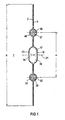
- ein erstes Ausführungsbeispiel einer flexiblen Lanze nach der Erfindung in einer Querschnittsdar- stellung,
- FIG 2
- zwei Bänder der flexiblen Lanze der
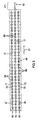
Figur 1 vor ih- rem Verbinden in einer Längsansicht, - FIG 3
- eine Querschnittsdarstellung des ersten Bands der flexiblen Lanze der
Figur 1 , - FIG 4
- eine Querschnittsdarstellung des zweiten Bands der flexiblen Lanze der
Figur 1 , - FIG 5
- ein zweites Ausführungsbeispiel der flexiblen Lanze nach der Erfindung in einer Querschnittsdarstel- lung,
- FIG 6
- die flexible
Lanze der Figur 3 in einer Längsan- sicht und - FIG 7
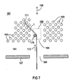
- eine schematische Darstellung des Einsatzes der flexiblen Lanze beim Bearbeiten oder Inspizieren eines Rohrbodens eines Dampferzeugers.
- FIG. 1
- A first embodiment of a flexible lance according to the invention in a cross-sectional view,
- FIG. 2
- two bands of flexible lance the
FIG. 1 before joining in a longitudinal view, - FIG. 3
- a cross-sectional view of the first band of the flexible lance of
FIG. 1 . - FIG. 4
- a cross-sectional view of the second band of the flexible lance of
FIG. 1 . - FIG. 5
- A second embodiment of the flexible lance according to the invention in a cross-sectional representation,
- FIG. 6
- the flexible lance of the
FIG. 3 in a longitudinal view and - FIG. 7
- a schematic representation of the use of the flexible lance when working or inspecting a tube plate of a steam generator.
In
Die beiden Versorgungsleitungen 17, 19 sind symmetrisch beidseitig einer Mittenachse 21 angeordnet.The two
Die beiden Bänder 3, 5 sind durch zwei Sehnen 27, 29 miteinander verbunden. Die beiden Sehnen 27, 29 sind symmetrisch beidseitig der Mittenachse 21 angebracht. Ihr gegenseitiger Abstand a beträgt etwa 15 mm.The two
Die beiden Bänder 3, 5 schlingen sich jeweils abwechselnd um jede der beiden Sehnen 27, 29, so dass an jeder der beiden Sehnen 27, 29 abwechselnd das erste Band 3 und das zweite Band 5 anliegt. Dadurch sind die beiden Bänder 3, 5 in gleichsam einfacher und flexibler Weise miteinander verbunden.The two
In
Aus
Der Abstand d der - in Längsrichtung - nur wenige Zehntel Millimeter breiten und lasergeschnittenen schlitzartigen Ausnehmungen 33, 35 beträgt etwa 5 mm, die Schlitzbreite etwa 7 mm. Dadurch ergibt sich ein minimaler Krümmungsradius von ca. 40 mm.The distance d of the - in the longitudinal direction - only a few tenths of a millimeter wide and laser-cut slot-
In
Die beiden Bänder 3, 5 sind im Bereich ihrer mittigen Ausformungen 13 bzw. 15 und bezüglich ihrer Reihen 43 bzw. 45 hintereinander angeordneter Öffnungen 44 bzw. 46 weitgehend identisch. Zur Bildung der flexiblen Lanze 1 werden die Bänder 3, 5 quasi um 180° phasenverschoben bündig übereinander gelegt. Dies ist mittels der Hilfslinie 30 angedeutet. Beim Zusammenfügen zur flexiblen Lanze 1 kommen die ausgeformten Bereiche 48 zwischen den Öffnungen 44 des ersten Bands 3 in den Öffnungen 46 des zweiten Bands 5 zu liegen und ragen in diese Öffnungen 46 hinein. In gleicher Weise ragen die ausgeformten Bereiche 49 in entgegengesetzter Richtung in die Öffnungen 44 des ersten Bands 3 hinein. In diesem Zustand ist durch die ausgeformten Bereiche 48 und 49 ein geradliniger Kanal zur Aufnahme der ersten Sehne 27 gebildet. Durch Einführen der ersten Sehne 27 in diesen Kanal werden die beiden Bänder 3, 5 miteinander verbunden, wie dies im Ergebnis in
Weitere Reihen äquidistanter Öffnungen mit ausgeformten Bereichen 50 des Bands 3 (siehe auch
Die beiden Sehnen 27, 29 sind als mehrfaseriges Stahlseil ausgeführt, das steifer als die Bänder 3, 5 ist.The two
Außenliegend weist das erste Band 3 Reihen 52, 53 weiterer Öffnungen auf, die dem Eingriff einer nicht explizit dargestellten Vorschubeinrichtung dienen. In gleicher Weise weist das zweite Band 5 außenliegend Reihen 54, 55 von Öffnungen auf, die im Vergleich zu den Öffnungen der Reihen 52, 53 des ersten Bands 3 in Längsrichtung 31 eine größere Ausdehnung aufweisen. Dadurch ist sichergestellt, dass beispielsweise ein Zahnrad der genannten Vorschubeinrichtung nur an den Öffnungen der Reihen 52, 53 des ersten Bands 3 zum Angriff kommt, was von Bedeutung ist, wenn sich, insbesondere bei kleinem Krümmungsradius, die beiden Bänder 3, 5 in Längsrichtung 31 leicht relativ zueinander verschieben. Ein Verklemmen der Lanze 1 am Zahnrad ist somit ausgeschlossen.On the outside, the
Ein zweites Ausführungsbeispiel einer flexiblen Lanze 1 nach der Erfindung ist in
In
Weitere Einzelheiten des Manipulators 169 sowie Details zum angesprochenen Verwendungszweck sind in den Spalten 4 bis 7 der
Claims (12)
- Flexible lance (1) for working on or inspecting a tube plate (161) of a steam generator (163), having an integral, flexible metallic first strip (3; 60) and a supply line (17, 19), which is guided on the said first strip in the longitudinal direction (31), for a working or inspection head (171) which is arranged at the free end of the first strip (3; 60),
with a first tendon (27) which is arranged on the first strip (3; 60) in the longitudinal direction (31) having a higher flexural stiffness than the strip (3; 60). - Flexible lance (1) according to Claim 1, characterized in that the first tendon (27) does not serve to supply or actuate the working or inspection head (171).
- Flexible lance (1) according to Claim 1 or 2, characterized in that the supply line (17, 19) is a hose, a capillary, an electrical line or an optical glass fibre.
- Flexible lance (1) according to one of Claims 1 to 3,
characterized in that the strip (3, 5; 60) has openings (44, 46; 64) which are arranged successively in the longitudinal direction (31) and through which the first tendon (27) is threaded. - Flexible lance (1) according to Claim 4,
characterized in that the strip (60) between its openings (64) has regions (70, 71) which are formed perpendicular with respect to the longitudinal direction (31) and extend on one side and on the other side of the strip (60) in an alternating fashion. - Flexible lance (1) according to one of Claims 1 to 5,
characterized by a second tendon (29) which has a higher flexural stiffness than the strip (3, 5; 60) and is attached in the same manner as the first tendon (27) and at a distance therefrom. - Flexible lance (1) according to Claim 6,
characterized in that the two tendons (27, 29) are arranged symmetrically in relation to the supply line (17, 19). - Flexible lance (1) according to one of Claims 1 to 7,
characterized in that the first tendon (27) or one of the tendons (27, 29) is in the form of a wire, in particular in the form of a spring steel wire, in the form of a cable, in particular in the form of a steel cable, and/or in the form of a fibreglass element. - Flexible lance (1) according to one of Claims 1 to 8,
characterized by an integral flexible metallic second strip (5) which is arranged in the longitudinal direction (31) and is connected to the first strip (3). - Flexible lance (1) according to Claim 9,
characterized in that the first strip (3) and the second strip (5) are connected to one another by the first tendon (27). - Flexible lance (1) according to Claim 9 or 10,
characterized in that the open side of a first formation (13) on the first strip (3) for holding the supply line (17, 19) is covered by the second strip (5) so as to form a guiding passage (16). - Flexible lance (1) according to one of Claims 9 to 11,
characterized in that the second strip (5) is formed with a second formation (15), which extends in the longitudinal direction (31), on the other side to the first strip (3) in order to form the guiding passage (16).
Applications Claiming Priority (2)
| Application Number | Priority Date | Filing Date | Title |
|---|---|---|---|
| DE10006066 | 2000-02-10 | ||
| DE10006066A DE10006066A1 (en) | 2000-02-10 | 2000-02-10 | Flexible lance for processing or inspecting a tube sheet of a steam generator |
Publications (3)
| Publication Number | Publication Date |
|---|---|
| EP1124093A2 EP1124093A2 (en) | 2001-08-16 |
| EP1124093A3 EP1124093A3 (en) | 2003-02-19 |
| EP1124093B1 true EP1124093B1 (en) | 2011-11-09 |
Family
ID=7630571
Family Applications (1)
| Application Number | Title | Priority Date | Filing Date |
|---|---|---|---|
| EP01101967A Expired - Lifetime EP1124093B1 (en) | 2000-02-10 | 2001-01-29 | Flexible lance for working on or inspecting a tube plate of a steam generator |
Country Status (4)
| Country | Link |
|---|---|
| EP (1) | EP1124093B1 (en) |
| AT (1) | ATE533012T1 (en) |
| DE (1) | DE10006066A1 (en) |
| ES (1) | ES2377850T3 (en) |
Families Citing this family (4)
| Publication number | Priority date | Publication date | Assignee | Title |
|---|---|---|---|---|
| DE10006056A1 (en) * | 2000-02-10 | 2001-08-30 | Siemens Ag | Flexible lance for inspection of steam generator - has 2 flexible metallic bands sandwiched together to provide longitudinal guide sleeve for supply line for treatment or inspection head |
| DE102013101656B4 (en) | 2013-02-20 | 2015-04-16 | Areva Gmbh | Lance for removing deposits adhering to the tube bottom of a steam generator |
| DE102015118615B3 (en) * | 2015-10-30 | 2016-09-01 | Areva Gmbh | Flexible lance for working or inspecting a tube plate of a steam generator |
| KR102212469B1 (en) * | 2019-04-23 | 2021-02-05 | 두산중공업 주식회사 | Inspection device for steam generator |
Family Cites Families (6)
| Publication number | Priority date | Publication date | Assignee | Title |
|---|---|---|---|---|
| FR2514108B1 (en) * | 1981-10-06 | 1986-06-13 | Framatome Sa | PROCESS AND DEVICE FOR REMOVING SLUDGE FROM THE TUBULAR PLATE OF STEAM GENERATORS |
| EP0459597A1 (en) * | 1987-03-18 | 1991-12-04 | Electric Power Research Institute, Inc | Flexible lance for steam generator secondary side sludge removal |
| US5286154A (en) * | 1987-03-18 | 1994-02-15 | Electric Power Research Institute, Inc. | In bundle foreign object search and retrieval apparatus |
| JP3599745B2 (en) * | 1995-03-15 | 2004-12-08 | フラマトム アンプ ゲゼルシャフト ミット ベシュレンクテル ハフツング | Flexible lance for processing or inspection of steam generator tube floor |
| WO1998044291A1 (en) * | 1997-03-28 | 1998-10-08 | Electric Power Research Institute, Inc. | Variable tension lance support |
| DE10006056A1 (en) * | 2000-02-10 | 2001-08-30 | Siemens Ag | Flexible lance for inspection of steam generator - has 2 flexible metallic bands sandwiched together to provide longitudinal guide sleeve for supply line for treatment or inspection head |
-
2000
- 2000-02-10 DE DE10006066A patent/DE10006066A1/en not_active Ceased
-
2001
- 2001-01-29 ES ES01101967T patent/ES2377850T3/en not_active Expired - Lifetime
- 2001-01-29 EP EP01101967A patent/EP1124093B1/en not_active Expired - Lifetime
- 2001-01-29 AT AT01101967T patent/ATE533012T1/en active
Also Published As
| Publication number | Publication date |
|---|---|
| ATE533012T1 (en) | 2011-11-15 |
| EP1124093A3 (en) | 2003-02-19 |
| EP1124093A2 (en) | 2001-08-16 |
| DE10006066A1 (en) | 2001-08-30 |
| ES2377850T3 (en) | 2012-04-02 |
Similar Documents
| Publication | Publication Date | Title |
|---|---|---|
| DE10010935C1 (en) | Cable holder for vehicle structures | |
| EP0479839B1 (en) | Fibre-optic cable with at least one optical fibre | |
| EP0270479B1 (en) | Splice cartridge case for light wave guides | |
| DE102004022938B4 (en) | Protective and guiding device for a cable or hose, comprising a cable protection lamella | |
| DE2626907A1 (en) | COUPLING FOR OPTICAL FIBERS | |
| DE102006029531A1 (en) | Slide for passing cables through flexible ducts comprises spaced units made up of parallel rails linked by connector blocks fitted with transverse pins which act as pivots | |
| DE2821562B2 (en) | Reinforcement grids for concrete, especially for securing underground cavities | |
| EP0815388B1 (en) | Flexible lance for working on or inspecting a tube base of a steam generator | |
| EP1124093B1 (en) | Flexible lance for working on or inspecting a tube plate of a steam generator | |
| EP1847745A2 (en) | Line-coupling | |
| EP1124092B1 (en) | Flexible lance for working on or inspecting a tube plate of a steam generator | |
| EP0938633B1 (en) | Energy supply line guiding chain and rigid bar chain link | |
| EP0331099B1 (en) | Tube bundle for receiving cables | |
| DE102020202461A1 (en) | Energy supply system for flexible energy conductors | |
| DE10143969B4 (en) | Elbows holder | |
| DE10314937B4 (en) | Plastic profile strip for holding a plurality of electrical lines | |
| DE102015118615B3 (en) | Flexible lance for working or inspecting a tube plate of a steam generator | |
| DE102007005059A1 (en) | Cable arrangement for the maintenance of moving machines with current, compressed air, cooling water, has cable that is surrounded partly by foam block extending in its longitudinal direction | |
| DE4445137C2 (en) | Device for holding pipes of a heat exchanger | |
| EP0260403A1 (en) | Spacer with strips of a tube spacing grid | |
| EP2718216B1 (en) | Cable guide for fibres that are combined in cables | |
| EP0815389A1 (en) | Device and process for treating or inspecting a pipe floor in a steam generator | |
| EP0202418A2 (en) | Frame portion for a contact element strip of a plug connection | |
| DE202020102173U1 (en) | Strain relief | |
| EP0694748A1 (en) | Pipe unit |
Legal Events
| Date | Code | Title | Description |
|---|---|---|---|
| PUAI | Public reference made under article 153(3) epc to a published international application that has entered the european phase |
Free format text: ORIGINAL CODE: 0009012 |
|
| AK | Designated contracting states |
Kind code of ref document: A2 Designated state(s): AT BE CH CY DE DK ES FI FR GB GR IE IT LI LU MC NL PT SE TR |
|
| AX | Request for extension of the european patent |
Free format text: AL;LT;LV;MK;RO;SI |
|
| RAP1 | Party data changed (applicant data changed or rights of an application transferred) |
Owner name: FRAMATOME ANP GMBH |
|
| PUAL | Search report despatched |
Free format text: ORIGINAL CODE: 0009013 |
|
| AK | Designated contracting states |
Designated state(s): AT BE CH CY DE DK ES FI FR GB GR IE IT LI LU MC NL PT SE TR |
|
| AX | Request for extension of the european patent |
Extension state: AL LT LV MK RO SI |
|
| 17P | Request for examination filed |
Effective date: 20030308 |
|
| AKX | Designation fees paid |
Designated state(s): AT BE CH CY DE DK ES FI FR GB GR IE IT LI LU MC NL PT SE TR |
|
| RAP1 | Party data changed (applicant data changed or rights of an application transferred) |
Owner name: AREVA NP GMBH |
|
| RAP1 | Party data changed (applicant data changed or rights of an application transferred) |
Owner name: AREVA NP GMBH |
|
| 17Q | First examination report despatched |
Effective date: 20080411 |
|
| GRAP | Despatch of communication of intention to grant a patent |
Free format text: ORIGINAL CODE: EPIDOSNIGR1 |
|
| GRAS | Grant fee paid |
Free format text: ORIGINAL CODE: EPIDOSNIGR3 |
|
| GRAA | (expected) grant |
Free format text: ORIGINAL CODE: 0009210 |
|
| AK | Designated contracting states |
Kind code of ref document: B1 Designated state(s): AT BE CH CY DE DK ES FI FR GB GR IE IT LI LU MC NL PT SE TR |
|
| REG | Reference to a national code |
Ref country code: GB Ref legal event code: FG4D Free format text: NOT ENGLISH |
|
| REG | Reference to a national code |
Ref country code: CH Ref legal event code: EP |
|
| REG | Reference to a national code |
Ref country code: IE Ref legal event code: FG4D Free format text: LANGUAGE OF EP DOCUMENT: GERMAN |
|
| REG | Reference to a national code |
Ref country code: DE Ref legal event code: R096 Ref document number: 50115997 Country of ref document: DE Effective date: 20120119 |
|
| REG | Reference to a national code |
Ref country code: CH Ref legal event code: NV Representative=s name: E. BLUM & CO. AG PATENT- UND MARKENANWAELTE VSP |
|
| REG | Reference to a national code |
Ref country code: NL Ref legal event code: T3 |
|
| REG | Reference to a national code |
Ref country code: DE Ref legal event code: R082 Ref document number: 50115997 Country of ref document: DE Representative=s name: ALFRED MOERTEL, DE Ref country code: DE Ref legal event code: R082 Ref document number: 50115997 Country of ref document: DE Representative=s name: MOERTEL, ALFRED, DIPL.-PHYS. DR.RER.NAT., DE |
|
| REG | Reference to a national code |
Ref country code: SE Ref legal event code: TRGR |
|
| REG | Reference to a national code |
Ref country code: ES Ref legal event code: FG2A Ref document number: 2377850 Country of ref document: ES Kind code of ref document: T3 Effective date: 20120402 |
|
| PG25 | Lapsed in a contracting state [announced via postgrant information from national office to epo] |
Ref country code: PT Free format text: LAPSE BECAUSE OF FAILURE TO SUBMIT A TRANSLATION OF THE DESCRIPTION OR TO PAY THE FEE WITHIN THE PRESCRIBED TIME-LIMIT Effective date: 20120309 Ref country code: GR Free format text: LAPSE BECAUSE OF FAILURE TO SUBMIT A TRANSLATION OF THE DESCRIPTION OR TO PAY THE FEE WITHIN THE PRESCRIBED TIME-LIMIT Effective date: 20120210 |
|
| REG | Reference to a national code |
Ref country code: IE Ref legal event code: FD4D |
|
| PG25 | Lapsed in a contracting state [announced via postgrant information from national office to epo] |
Ref country code: CY Free format text: LAPSE BECAUSE OF FAILURE TO SUBMIT A TRANSLATION OF THE DESCRIPTION OR TO PAY THE FEE WITHIN THE PRESCRIBED TIME-LIMIT Effective date: 20111109 |
|
| PG25 | Lapsed in a contracting state [announced via postgrant information from national office to epo] |
Ref country code: IE Free format text: LAPSE BECAUSE OF FAILURE TO SUBMIT A TRANSLATION OF THE DESCRIPTION OR TO PAY THE FEE WITHIN THE PRESCRIBED TIME-LIMIT Effective date: 20111109 Ref country code: DK Free format text: LAPSE BECAUSE OF FAILURE TO SUBMIT A TRANSLATION OF THE DESCRIPTION OR TO PAY THE FEE WITHIN THE PRESCRIBED TIME-LIMIT Effective date: 20111109 |
|
| PG25 | Lapsed in a contracting state [announced via postgrant information from national office to epo] |
Ref country code: MC Free format text: LAPSE BECAUSE OF NON-PAYMENT OF DUE FEES Effective date: 20120131 |
|
| PLBE | No opposition filed within time limit |
Free format text: ORIGINAL CODE: 0009261 |
|
| STAA | Information on the status of an ep patent application or granted ep patent |
Free format text: STATUS: NO OPPOSITION FILED WITHIN TIME LIMIT |
|
| 26N | No opposition filed |
Effective date: 20120810 |
|
| REG | Reference to a national code |
Ref country code: DE Ref legal event code: R097 Ref document number: 50115997 Country of ref document: DE Effective date: 20120810 |
|
| REG | Reference to a national code |
Ref country code: AT Ref legal event code: MM01 Ref document number: 533012 Country of ref document: AT Kind code of ref document: T Effective date: 20120129 |
|
| PG25 | Lapsed in a contracting state [announced via postgrant information from national office to epo] |
Ref country code: AT Free format text: LAPSE BECAUSE OF NON-PAYMENT OF DUE FEES Effective date: 20120129 |
|
| REG | Reference to a national code |
Ref country code: DE Ref legal event code: R082 Ref document number: 50115997 Country of ref document: DE Representative=s name: MOERTEL, ALFRED, DIPL.-PHYS. DR.RER.NAT., DE |
|
| REG | Reference to a national code |
Ref country code: DE Ref legal event code: R081 Ref document number: 50115997 Country of ref document: DE Owner name: AREVA GMBH, DE Free format text: FORMER OWNER: AREVA NP GMBH, 91052 ERLANGEN, DE Effective date: 20131112 Ref country code: DE Ref legal event code: R082 Ref document number: 50115997 Country of ref document: DE Representative=s name: MOERTEL, ALFRED, DIPL.-PHYS. DR.RER.NAT., DE Effective date: 20131112 Ref country code: DE Ref legal event code: R081 Ref document number: 50115997 Country of ref document: DE Owner name: AREVA GMBH, DE Free format text: FORMER OWNER: SIEMENS AKTIENGESELLSCHAFT, 80333 MUENCHEN, DE Effective date: 20111125 Ref country code: DE Ref legal event code: R082 Ref document number: 50115997 Country of ref document: DE Representative=s name: MOERTEL, ALFRED, DIPL.-PHYS. DR.RER.NAT., DE Effective date: 20120227 Ref country code: DE Ref legal event code: R082 Ref document number: 50115997 Country of ref document: DE Representative=s name: MEISSNER BOLTE & PARTNER GBR, DE Effective date: 20131112 Ref country code: DE Ref legal event code: R082 Ref document number: 50115997 Country of ref document: DE Representative=s name: MEISSNER BOLTE & PARTNER GBR, DE Effective date: 20120227 Ref country code: DE Ref legal event code: R082 Ref document number: 50115997 Country of ref document: DE Representative=s name: MEISSNER BOLTE PATENTANWAELTE RECHTSANWAELTE P, DE Effective date: 20120227 Ref country code: DE Ref legal event code: R082 Ref document number: 50115997 Country of ref document: DE Representative=s name: MEISSNER BOLTE PATENTANWAELTE RECHTSANWAELTE P, DE Effective date: 20131112 |
|
| REG | Reference to a national code |
Ref country code: DE Ref legal event code: R082 Ref document number: 50115997 Country of ref document: DE Representative=s name: MEISSNER BOLTE & PARTNER GBR, DE Ref country code: DE Ref legal event code: R082 Ref document number: 50115997 Country of ref document: DE Representative=s name: MEISSNER BOLTE PATENTANWAELTE RECHTSANWAELTE P, DE |
|
| PG25 | Lapsed in a contracting state [announced via postgrant information from national office to epo] |
Ref country code: TR Free format text: LAPSE BECAUSE OF FAILURE TO SUBMIT A TRANSLATION OF THE DESCRIPTION OR TO PAY THE FEE WITHIN THE PRESCRIBED TIME-LIMIT Effective date: 20111109 |
|
| PG25 | Lapsed in a contracting state [announced via postgrant information from national office to epo] |
Ref country code: LU Free format text: LAPSE BECAUSE OF NON-PAYMENT OF DUE FEES Effective date: 20120129 |
|
| REG | Reference to a national code |
Ref country code: FR Ref legal event code: PLFP Year of fee payment: 16 |
|
| REG | Reference to a national code |
Ref country code: DE Ref legal event code: R082 Ref document number: 50115997 Country of ref document: DE Representative=s name: MEISSNER BOLTE PATENTANWAELTE RECHTSANWAELTE P, DE |
|
| REG | Reference to a national code |
Ref country code: FR Ref legal event code: PLFP Year of fee payment: 17 |
|
| REG | Reference to a national code |
Ref country code: FR Ref legal event code: PLFP Year of fee payment: 18 |
|
| PGFP | Annual fee paid to national office [announced via postgrant information from national office to epo] |
Ref country code: GB Payment date: 20180125 Year of fee payment: 18 Ref country code: DE Payment date: 20180124 Year of fee payment: 18 |
|
| PGFP | Annual fee paid to national office [announced via postgrant information from national office to epo] |
Ref country code: SE Payment date: 20180125 Year of fee payment: 18 Ref country code: BE Payment date: 20180124 Year of fee payment: 18 Ref country code: IT Payment date: 20180126 Year of fee payment: 18 |
|
| REG | Reference to a national code |
Ref country code: CH Ref legal event code: PFA Owner name: AREVA GMBH, DE Free format text: FORMER OWNER: AREVA NP GMBH, DE Ref country code: CH Ref legal event code: PUE Owner name: FRAMATOME GMBH, DE Free format text: FORMER OWNER: AREVA GMBH, DE |
|
| REG | Reference to a national code |
Ref country code: NL Ref legal event code: HC Owner name: AREVA GMBH; DE Free format text: DETAILS ASSIGNMENT: CHANGE OF OWNER(S), CHANGE OF OWNER(S) NAME; FORMER OWNER NAME: AREVA NP GMBH Effective date: 20190111 Ref country code: NL Ref legal event code: PD Owner name: FRAMATOME GMBH; DE Free format text: DETAILS ASSIGNMENT: CHANGE OF OWNER(S), ASSIGNMENT; FORMER OWNER NAME: AREVA GMBH Effective date: 20190111 |
|
| PGFP | Annual fee paid to national office [announced via postgrant information from national office to epo] |
Ref country code: CH Payment date: 20190124 Year of fee payment: 19 Ref country code: NL Payment date: 20190122 Year of fee payment: 19 Ref country code: FI Payment date: 20190118 Year of fee payment: 19 Ref country code: FR Payment date: 20190123 Year of fee payment: 19 Ref country code: ES Payment date: 20190215 Year of fee payment: 19 |
|
| REG | Reference to a national code |
Ref country code: ES Ref legal event code: PC2A Owner name: FRAMATOME GMBH Effective date: 20190516 |
|
| REG | Reference to a national code |
Ref country code: DE Ref legal event code: R119 Ref document number: 50115997 Country of ref document: DE |
|
| GBPC | Gb: european patent ceased through non-payment of renewal fee |
Effective date: 20190129 |
|
| REG | Reference to a national code |
Ref country code: BE Ref legal event code: MM Effective date: 20190131 |
|
| PG25 | Lapsed in a contracting state [announced via postgrant information from national office to epo] |
Ref country code: SE Free format text: LAPSE BECAUSE OF NON-PAYMENT OF DUE FEES Effective date: 20190130 Ref country code: DE Free format text: LAPSE BECAUSE OF NON-PAYMENT OF DUE FEES Effective date: 20190801 |
|
| PG25 | Lapsed in a contracting state [announced via postgrant information from national office to epo] |
Ref country code: BE Free format text: LAPSE BECAUSE OF NON-PAYMENT OF DUE FEES Effective date: 20190131 |
|
| PG25 | Lapsed in a contracting state [announced via postgrant information from national office to epo] |
Ref country code: GB Free format text: LAPSE BECAUSE OF NON-PAYMENT OF DUE FEES Effective date: 20190129 |
|
| PG25 | Lapsed in a contracting state [announced via postgrant information from national office to epo] |
Ref country code: IT Free format text: LAPSE BECAUSE OF NON-PAYMENT OF DUE FEES Effective date: 20190129 |
|
| REG | Reference to a national code |
Ref country code: FI Ref legal event code: MAE |
|
| REG | Reference to a national code |
Ref country code: CH Ref legal event code: PL |
|
| REG | Reference to a national code |
Ref country code: NL Ref legal event code: MM Effective date: 20200201 |
|
| PG25 | Lapsed in a contracting state [announced via postgrant information from national office to epo] |
Ref country code: NL Free format text: LAPSE BECAUSE OF NON-PAYMENT OF DUE FEES Effective date: 20200201 Ref country code: FI Free format text: LAPSE BECAUSE OF NON-PAYMENT OF DUE FEES Effective date: 20200129 Ref country code: FR Free format text: LAPSE BECAUSE OF NON-PAYMENT OF DUE FEES Effective date: 20200131 |
|
| PG25 | Lapsed in a contracting state [announced via postgrant information from national office to epo] |
Ref country code: LI Free format text: LAPSE BECAUSE OF NON-PAYMENT OF DUE FEES Effective date: 20200131 Ref country code: CH Free format text: LAPSE BECAUSE OF NON-PAYMENT OF DUE FEES Effective date: 20200131 |
|
| REG | Reference to a national code |
Ref country code: ES Ref legal event code: FD2A Effective date: 20210603 |
|
| PG25 | Lapsed in a contracting state [announced via postgrant information from national office to epo] |
Ref country code: ES Free format text: LAPSE BECAUSE OF NON-PAYMENT OF DUE FEES Effective date: 20200130 |