EP0260403A1 - Spacer with strips of a tube spacing grid - Google Patents
Spacer with strips of a tube spacing grid Download PDFInfo
- Publication number
- EP0260403A1 EP0260403A1 EP87110263A EP87110263A EP0260403A1 EP 0260403 A1 EP0260403 A1 EP 0260403A1 EP 87110263 A EP87110263 A EP 87110263A EP 87110263 A EP87110263 A EP 87110263A EP 0260403 A1 EP0260403 A1 EP 0260403A1
- Authority
- EP
- European Patent Office
- Prior art keywords
- bars
- spacer
- lattice
- frame
- grid
- Prior art date
- Legal status (The legal status is an assumption and is not a legal conclusion. Google has not performed a legal analysis and makes no representation as to the accuracy of the status listed.)
- Granted
Links
- 125000006850 spacer group Chemical group 0.000 title claims abstract description 26
- 239000000463 material Substances 0.000 description 2
- 238000010276 construction Methods 0.000 description 1
- 238000011010 flushing procedure Methods 0.000 description 1
- 239000007788 liquid Substances 0.000 description 1
Images
Classifications
-
- F—MECHANICAL ENGINEERING; LIGHTING; HEATING; WEAPONS; BLASTING
- F28—HEAT EXCHANGE IN GENERAL
- F28F—DETAILS OF HEAT-EXCHANGE AND HEAT-TRANSFER APPARATUS, OF GENERAL APPLICATION
- F28F9/00—Casings; Header boxes; Auxiliary supports for elements; Auxiliary members within casings
-
- F—MECHANICAL ENGINEERING; LIGHTING; HEATING; WEAPONS; BLASTING
- F28—HEAT EXCHANGE IN GENERAL
- F28F—DETAILS OF HEAT-EXCHANGE AND HEAT-TRANSFER APPARATUS, OF GENERAL APPLICATION
- F28F9/00—Casings; Header boxes; Auxiliary supports for elements; Auxiliary members within casings
- F28F9/007—Auxiliary supports for elements
- F28F9/013—Auxiliary supports for elements for tubes or tube-assemblies
- F28F9/0135—Auxiliary supports for elements for tubes or tube-assemblies formed by grids having only one tube per closed grid opening
- F28F9/0136—Auxiliary supports for elements for tubes or tube-assemblies formed by grids having only one tube per closed grid opening formed by intersecting strips
-
- F—MECHANICAL ENGINEERING; LIGHTING; HEATING; WEAPONS; BLASTING
- F22—STEAM GENERATION
- F22B—METHODS OF STEAM GENERATION; STEAM BOILERS
- F22B37/00—Component parts or details of steam boilers
- F22B37/02—Component parts or details of steam boilers applicable to more than one kind or type of steam boiler
- F22B37/10—Water tubes; Accessories therefor
- F22B37/20—Supporting arrangements, e.g. for securing water-tube sets
- F22B37/205—Supporting and spacing arrangements for tubes of a tube bundle
-
- Y—GENERAL TAGGING OF NEW TECHNOLOGICAL DEVELOPMENTS; GENERAL TAGGING OF CROSS-SECTIONAL TECHNOLOGIES SPANNING OVER SEVERAL SECTIONS OF THE IPC; TECHNICAL SUBJECTS COVERED BY FORMER USPC CROSS-REFERENCE ART COLLECTIONS [XRACs] AND DIGESTS
- Y10—TECHNICAL SUBJECTS COVERED BY FORMER USPC
- Y10S—TECHNICAL SUBJECTS COVERED BY FORMER USPC CROSS-REFERENCE ART COLLECTIONS [XRACs] AND DIGESTS
- Y10S165/00—Heat exchange
- Y10S165/355—Heat exchange having separate flow passage for two distinct fluids
- Y10S165/40—Shell enclosed conduit assembly
- Y10S165/401—Shell enclosed conduit assembly including tube support or shell-side flow director
- Y10S165/416—Extending transverse of shell, e.g. fin, baffle
- Y10S165/423—Bar
- Y10S165/424—Bar forming grid structure
Definitions
- the lattice bars are fastened in the frame in different ways.
- the bars are rigidly connected to the frame.
- spacers are provided which allow a certain freedom of movement for the grille, which enables thermal compensation. This compensation option is important if the grating and frame are made of different materials.
- a cross slot (5) in the spacer bolt (1) extends over the lattice bar (3) and positions it in the lattice frame (2).
- the spacer pin engages in a recess (7) in the lattice bar (3) and thus prevents the lattice bar (3) from being pulled out of the lattice frame (2).
- a paste-like plastic (9) can be inserted between the bolt slots (5) and tubular bars (3) through a longitudinal hole (8) after the lattice frame (2) has been fitted with bars (3) and spacer bolts (1). After the plastic (9) has hardened, a non-positive connection is made between the spacer bolts (1) and the lattice bars (3), so that the pipe spacing grid remains positioned and fixed in the lattice frame (2) for the subsequent operations.
Abstract
Die Erfindung betrifft ein Rohrabstandsgitter zum Führen von Rohren in Wärmetauschern, beispielsweise Dampferzeugern, wobei das Gitter aus sich kreuzenden, in mehr als einer Ebene angeordneten Gitterstäben gebildet und von einem Rahmen umgeben ist. Der Rahmen weist innenseitig umlaufende Nuten zur Aufnahme der Enden der Gitterstäbe auf. Die gegenseitige Abstandsfestlegung der Gitterstäbe (3) im Rahmen (2) erfolgt durch Distanzbolzen (1). Die Distanzbolzen (1) weisen einen Querschlitz (5) auf zur Aufnahme des Gitterstabes (3), ferner einen Vorsprung (6) im Querschlitz (5), der in eine entsprechende Ausnehmung (7) des Gitterstabes (3) eingreift. Die Distanzbolzen (1) sind durch einen umlaufenden Abdeckring (4) gegen Herausfallen gesichert. In eine Längsbohrung (8) des Distanzbolzens (1) kann pasteuser Kunststoff eingebracht werden, der nach Aushärtung das Gitter fixiert.The invention relates to a pipe spacing grid for guiding pipes in heat exchangers, for example steam generators, the grid being formed from intersecting grid bars arranged in more than one plane and surrounded by a frame. The frame has circumferential grooves on the inside for receiving the ends of the bars. The mutual spacing of the bars (3) in the frame (2) is carried out using spacers (1). The spacer bolts (1) have a transverse slot (5) for receiving the lattice rod (3), furthermore a projection (6) in the transverse slot (5) which engages in a corresponding recess (7) in the lattice rod (3). The spacer bolts (1) are secured against falling out by a circumferential cover ring (4). Paste-usable plastic can be introduced into a longitudinal bore (8) of the spacer bolt (1), which fixes the grid after curing.
Description
Die Erfindung betrifft einen Abstandshalter für Gitterstäbe eines Rohrabstandsgitters zum Führen von Rohren beispielsweise bei Dampferzeugern, wobei das Gitter aus sich kreuzenden, in mehr als einer Ebene angeordneten Gitterstäben gebildet und von einem Rahmen umgeben ist, der innenseitig umlaufende Nuten zur Aufnahme der Enden der Gitterstäbe aufweist.The invention relates to a spacer for bars of a pipe spacer for guiding pipes, for example in steam generators, the grid being formed from crossing bars arranged in more than one plane and being surrounded by a frame which has circumferential grooves on the inside for receiving the ends of the bars .
Zum Berohren von Wärmetauschern ist es notwendig, daß ein genau definierter Abstand der Rohrgitterstäbe eingehalten wird. Das Einhalten der geometrischen Gitterstruktur wird insbesondere durch die Befestigung der Gitterstabenden in der Rahmenkonstruktion des Gitterrostes erreicht.To touch heat exchangers, it is necessary to maintain a precisely defined distance between the pipe bars. Adherence to the geometric lattice structure is achieved in particular by fastening the ends of the lattice bars in the frame structure of the grating.
Nach dem Stand der Technik geschieht die Befestigung der Gitterstäbe im Rahmen auf unterschiedliche Weise. Bei einigen Ausführungen sind die Gitterstäbe mit dem Rahmen starr verbunden. Bei anderen Ausführungen sind Abstandshalter vorgesehen, die einen gewissen Bewegungsspielraum für das Gitter zulassen, der einen thermischen Ausgleich ermöglicht. Diese Ausgleichsmöglichkeit ist wichtig, wenn Gitterrost und Rahmen aus unterschiedlichen Werkstoffen bestehen.According to the prior art, the lattice bars are fastened in the frame in different ways. In some versions, the bars are rigidly connected to the frame. In other designs, spacers are provided which allow a certain freedom of movement for the grille, which enables thermal compensation. This compensation option is important if the grating and frame are made of different materials.
Aufgabe der Erfindung ist es, für ein Rohrabstandsgitter zur Führung der Rohrbündel von Wärmetauschern, insbesondere Dampferzeugern, eine Abstandshalterung im umlaufenden Gitterrostrahmen zu schaffen, die zum einen eine sichere Fixierung der Gitterstäbe für die Berohrung und die Montage gewährleistet, zum anderen darf aber im Betriebszustand des Wärmetauschers diese Fixierung nicht formschlüssig sein, weil unterschiedliche Wärmedehnungen zwischen Gitterstäben und Rahmen infolge der Materialunterschiede bei Stäben und Rahmen aufgefangen werden müssen.The object of the invention is to provide a spacer in the circumferential grating frame for a pipe spacing grid for guiding the tube bundle of heat exchangers, in particular steam generators, which on the one hand ensures a secure fixation of the grating bars for the tubing and the assembly, but on the other hand may in the operating state of the Heat exchanger this fixation should not be positive, because different thermal expansions between the bars and frame due to Material differences in bars and frames must be compensated.
Die Erfindung löst diese Aufgabe in der Weise, wie es in den Patentansprüchen angegeben ist.The invention solves this problem in the manner as specified in the claims.
Distanzbolzen bieten die Möglichkeit der Verwendung eines einteiligen Gitterrahmens mit möglichst geringem Profilquerschnitt und gewährleisten eine genaue Positionierung im Gitterrahmen.Spacer bolts offer the possibility of using a one-piece lattice frame with the smallest possible profile cross-section and ensure precise positioning in the lattice frame.
Nachdem die Abstandsfestlegung der Gitterstäbe im Gitterrahmen durch Aufsetzen der Distanzbolzen erfolgt ist, wird durch eine Längsbohrung im Distanzbolzen ein pasteuser Kunststoff zwischen Bolzenschlitz und Gitterstab eingebracht, der nach Aushärtung eine kraftschlüssige Verbindung von Bolzen und Gitterstab herstellt. Dieser eingebrachte Kunststoff wird, wenn sich der Wärmetauscher in Betrieb befindet, flüssig und durch das die Halterung mit bestimmter Temperatur umspülende Medium ausgespült, so daß temperaturbedingte Ausdehnungen innerhalb der Konstruktion Gitterstab - Rahmen stattfinden können.After the spacing of the lattice bars in the lattice frame has been established by attaching the spacer bolts, a paste-like plastic is inserted between the bolt slot and the lattice rod through a longitudinal hole in the spacer bolt, which creates a non-positive connection between the bolt and the lattice rod after curing. When the heat exchanger is in operation, this introduced plastic becomes liquid and is rinsed out through the medium, which is flushing around the holder with a certain temperature, so that temperature-related expansions can take place within the construction of the lattice bar frame.
Ein Ausführungsbeispiel der Erfindung wird nachstehend anhand der Zeichnung näher erläutert.An embodiment of the invention is explained below with reference to the drawing.
Es zeigen:
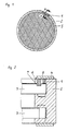
- Fig. 1 ein Rohrabstandsgitter in der Draufsicht,
- Fig. 2 einen Schnitt längs der Linie A-A gem. Fig. 1
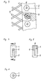
- Fig. 3 eine Teildraufsicht mit Ausbrüchen,
- Fig. 4 eine Vorderansicht des Distanzbolzens,
- Fig. 5 einen Schnitt längs der Linie B-B gem. Fig. 4,
- Fig. 6 eine Draufsicht des Distanzbolzens.
- 1 is a pipe spacing grid in plan view,
- Fig. 2 shows a section along the line AA according to. Fig. 1
- 3 is a partial top view with breakouts,
- 4 is a front view of the spacer bolt,
- Fig. 5 shows a section along the line BB acc. Fig. 4,
- Fig. 6 is a plan view of the spacer bolt.
Nach den Figuren wird ein Distanzbolzen (1) in eine Bohrung des Gitterrahmens (2) eingesetzt und durch einen aufliegenden Abdeckring (4) gesichert.According to the figures, a spacer bolt (1) is inserted into a hole in the lattice frame (2) and secured by an overlying cover ring (4).
Ein Querschlitz (5) im Distanzbolzen (1) greift über den Gitterstab (3) und positioniert diesen im Gitterrahmen (2).A cross slot (5) in the spacer bolt (1) extends over the lattice bar (3) and positions it in the lattice frame (2).
Mit einer im Querschlitz (5) liegenden Nase (6) greift der Distanzbolzen in eine Ausnehmung (7) des Gitterstabes (3) ein und verhindert damit ein Herausziehen des Gitterstabes (3) aus dem Gitterrahmen (2).With a nose (6) lying in the transverse slot (5), the spacer pin engages in a recess (7) in the lattice bar (3) and thus prevents the lattice bar (3) from being pulled out of the lattice frame (2).
Durch eine Längsbohrung (8) kann nach dem Bestücken des Gitterrahmens (2) mit Gitterstäben (3) und Distanzbolzen (1) ein pasteuser Kunststoff (9) zwischen die Bolzenschlitze (5) und Rohrgitterstäbe (3) eingebracht werd en. Nach Aushärtung des Kunststoffes (9) ist eine kraftschlüssige Verbindung zwischen den Distanzbolzen (1) und den Gitterstäben (3) hergestellt, so daß für die nachfolgenden Arbeitsgänge das Rohrabstandsgitter im Gitterrahmen (2) positioniert und fixiert bleibt.A paste-like plastic (9) can be inserted between the bolt slots (5) and tubular bars (3) through a longitudinal hole (8) after the lattice frame (2) has been fitted with bars (3) and spacer bolts (1). After the plastic (9) has hardened, a non-positive connection is made between the spacer bolts (1) and the lattice bars (3), so that the pipe spacing grid remains positioned and fixed in the lattice frame (2) for the subsequent operations.
Während des Betriebes wird der Kunststoff (9) durch das ihn umspielende Medium bei einer bestimmten Temperatur ausgespült und gibt somit den Gitterstab (3) für temperaturbedingte Längenausdehnungen frei. During operation, the plastic (9) is rinsed out by the medium surrounding it at a certain temperature and thus releases the lattice rod (3) for temperature-related linear expansion.
Claims (3)
dadurch gekennzeichnet,
daß die gegenseitige Abstandsfestlegung der Gitterstäbe (3) im Rahmen (2) durch Distanzbolzen (1) erfolgt, die einen Querschlitz (5) zur Aufnahme des Gitterstabes (3) aufweisen, ferner einen Vorsprung (6) im Querschlitz (5), der in eine entsprechende Ausnehmung (7) des Gitterstabes (3) eingreift.1. Spacers for lattice bars of a pipe spacer lattice for guiding pipes, for example in steam generators, the lattice being formed from crossing lattice bars arranged in more than one plane and being surrounded by a frame which has circumferential grooves on the inside for receiving the ends of the lattice bars,
characterized,
that the mutual spacing of the bars (3) in the frame (2) by spacers (1), which have a transverse slot (5) for receiving the bars (3), and a projection (6) in the transverse slot (5), which in a corresponding recess (7) of the lattice bar (3) engages.
dadurch gekennzeichnet,
daß die Distanzbolzen (1) durch einen umlaufenden Abdeckring (4) gesichert sind.2. spacer for bars according to claim 1,
characterized,
that the spacer bolts (1) are secured by a circumferential cover ring (4).
dadurch gekennzeichnet,
daß der Distanzbolzen (1) mit einer Längsbohrung (8), ausgeführt als Durchgangs- oder Sacklochbohrung, versehen ist.3. spacer for bars according to claim 1,
characterized,
that the spacer bolt (1) is provided with a longitudinal bore (8), designed as a through or blind hole.
Applications Claiming Priority (2)
| Application Number | Priority Date | Filing Date | Title |
|---|---|---|---|
| DE3631886 | 1986-09-19 | ||
| DE19863631886 DE3631886A1 (en) | 1986-09-19 | 1986-09-19 | SPACER FOR GRID ROD OF A PIPE GRID IN HEAT EXCHANGERS |
Publications (2)
| Publication Number | Publication Date |
|---|---|
| EP0260403A1 true EP0260403A1 (en) | 1988-03-23 |
| EP0260403B1 EP0260403B1 (en) | 1991-05-15 |
Family
ID=6309923
Family Applications (1)
| Application Number | Title | Priority Date | Filing Date |
|---|---|---|---|
| EP87110263A Expired - Lifetime EP0260403B1 (en) | 1986-09-19 | 1987-07-16 | Spacer with strips of a tube spacing grid |
Country Status (6)
| Country | Link |
|---|---|
| US (1) | US4784220A (en) |
| EP (1) | EP0260403B1 (en) |
| KR (1) | KR880004288A (en) |
| DE (2) | DE3631886A1 (en) |
| ES (1) | ES2022219B3 (en) |
| IN (1) | IN170068B (en) |
Families Citing this family (4)
| Publication number | Priority date | Publication date | Assignee | Title |
|---|---|---|---|---|
| DE4038813C2 (en) * | 1990-12-05 | 1998-01-29 | Siemens Ag | Boiler arrangement |
| US5388638A (en) * | 1993-12-28 | 1995-02-14 | Phillips Petroleum Company | Rod baffle heat exchanger |
| US5527865A (en) * | 1995-03-24 | 1996-06-18 | The University Of North Carolina At Chapel Hill | Multi-phase polymerization process |
| DE19511265A1 (en) * | 1995-03-27 | 1996-10-02 | Siemens Ag | Lattice spacer |
Citations (3)
| Publication number | Priority date | Publication date | Assignee | Title |
|---|---|---|---|---|
| DE2262621A1 (en) * | 1972-12-21 | 1974-07-11 | Gutehoffnungshuette Sterkrade | PIPE APPARATUS, IN PARTICULAR STEAM GENERATORS |
| FR2223650A1 (en) * | 1973-03-30 | 1974-10-25 | Siemens Ag | |
| DE2541986A1 (en) * | 1975-06-09 | 1976-12-16 | Breda Termomeccanica Spa | PROCESS FOR MANUFACTURING A GRATING COMPOSED OF TWO DIFFERENT MATERIALS, WHICH CAN REMAIN INITIALLY STIFF AND ALLOWS DIFFERENT THERMAL EXPANSIONS AFTER COMMISSIONING |
Family Cites Families (4)
| Publication number | Priority date | Publication date | Assignee | Title |
|---|---|---|---|---|
| US3575236A (en) * | 1969-08-13 | 1971-04-20 | Combustion Eng | Formed plate tube spacer structure |
| IT1065374B (en) * | 1976-12-21 | 1985-02-25 | Breda Termomeccanica Spa | SUPPORT GRID FOR TUBES AND ITS ASSEMBLY IN A STEAM GENERATOR OR SIMILAR |
| IT1096096B (en) * | 1978-05-17 | 1985-08-17 | Soligno Vincenzo | GUIDE-SUPPORT OF THE GRID TYPE FOR PIPES FOR STEAM GENERATORS |
| US4570883A (en) * | 1983-04-29 | 1986-02-18 | Westinghouse Electric Corp. | Tube support grid |
-
1986
- 1986-09-19 DE DE19863631886 patent/DE3631886A1/en not_active Withdrawn
-
1987
- 1987-07-16 EP EP87110263A patent/EP0260403B1/en not_active Expired - Lifetime
- 1987-07-16 DE DE8787110263T patent/DE3770090D1/en not_active Expired - Fee Related
- 1987-07-16 ES ES87110263T patent/ES2022219B3/en not_active Expired - Lifetime
- 1987-09-08 US US07/093,824 patent/US4784220A/en not_active Expired - Fee Related
- 1987-09-10 IN IN661/MAS/87A patent/IN170068B/en unknown
- 1987-09-18 KR KR870010352A patent/KR880004288A/en not_active Application Discontinuation
Patent Citations (3)
| Publication number | Priority date | Publication date | Assignee | Title |
|---|---|---|---|---|
| DE2262621A1 (en) * | 1972-12-21 | 1974-07-11 | Gutehoffnungshuette Sterkrade | PIPE APPARATUS, IN PARTICULAR STEAM GENERATORS |
| FR2223650A1 (en) * | 1973-03-30 | 1974-10-25 | Siemens Ag | |
| DE2541986A1 (en) * | 1975-06-09 | 1976-12-16 | Breda Termomeccanica Spa | PROCESS FOR MANUFACTURING A GRATING COMPOSED OF TWO DIFFERENT MATERIALS, WHICH CAN REMAIN INITIALLY STIFF AND ALLOWS DIFFERENT THERMAL EXPANSIONS AFTER COMMISSIONING |
Also Published As
| Publication number | Publication date |
|---|---|
| US4784220A (en) | 1988-11-15 |
| DE3770090D1 (en) | 1991-06-20 |
| EP0260403B1 (en) | 1991-05-15 |
| IN170068B (en) | 1992-02-01 |
| DE3631886A1 (en) | 1988-03-31 |
| ES2022219B3 (en) | 1991-12-01 |
| KR880004288A (en) | 1988-06-03 |
Similar Documents
| Publication | Publication Date | Title |
|---|---|---|
| DE1439936A1 (en) | Fuel element for heterogeneous nuclear reactors | |
| DE1763241B2 (en) | ||
| DE1944932A1 (en) | Fuel element holder for nuclear reactors | |
| CH671429A5 (en) | ||
| DE3821666C2 (en) | ||
| EP0527244B1 (en) | Spacer grid for fuel elements with curved attached springs | |
| DE2162381A1 (en) | CORNER CONNECTOR FOR DOUBLE HOLLOW PROFILE STRUTS | |
| EP0260403A1 (en) | Spacer with strips of a tube spacing grid | |
| DE2238477C3 (en) | Fuel arrangement for an atomic nuclear reactor | |
| DE2313438B2 (en) | Tubular apparatus, in particular steam generators | |
| DE3630502A1 (en) | PIPE GRID FOR GUIDING THE TUBES OF EXAMPLE STEAM GENERATORS | |
| DE2840146C2 (en) | ||
| EP0433493B1 (en) | Nuclear reactor fuel assembly comprising spacergrids and method for their fabrication | |
| EP0647744B1 (en) | Reinforcement for concrete constructions at a constructional joint | |
| DE19526623C2 (en) | heat exchangers | |
| DE3148777C2 (en) | Grid ceiling, in particular strip grid ceiling | |
| DE20105913U1 (en) | Nuclear reactor fuel assembly | |
| DE2106218C3 (en) | Reinforcement element for concrete or the like | |
| DE3911792C2 (en) | Heat exchangers, in particular coolers for a motor vehicle | |
| DE10010229C1 (en) | Holding device, for fixing at least one field pipe to pipe rack of scaffolding, comprises at least one spring element connected to at least one arm | |
| DE3710681C1 (en) | Lagging mat for mine support | |
| DE2142621A1 (en) | CONNECTION OF RECTANGULAR PROFILES | |
| DE1564434C3 (en) | Spacers for fuel assemblies with a wide variety of fuel rods | |
| DE19951913A1 (en) | Spacer for two shells of cavity wall has associated coupling device to couple to transport anchor and/or to reinforcement stay for cavity wall | |
| EP0224668A1 (en) | Tube support grid for, e.g., steam generators |
Legal Events
| Date | Code | Title | Description |
|---|---|---|---|
| PUAI | Public reference made under article 153(3) epc to a published international application that has entered the european phase |
Free format text: ORIGINAL CODE: 0009012 |
|
| AK | Designated contracting states |
Kind code of ref document: A1 Designated state(s): BE CH DE ES FR GB IT LI NL SE |
|
| 17P | Request for examination filed |
Effective date: 19880525 |
|
| RAP1 | Party data changed (applicant data changed or rights of an application transferred) |
Owner name: MAN GUTEHOFFNUNGSHUETTE AKTIENGESELLSCHAFT |
|
| 17Q | First examination report despatched |
Effective date: 19900213 |
|
| GRAA | (expected) grant |
Free format text: ORIGINAL CODE: 0009210 |
|
| AK | Designated contracting states |
Kind code of ref document: B1 Designated state(s): BE CH DE ES FR GB IT LI NL SE |
|
| ET | Fr: translation filed | ||
| REF | Corresponds to: |
Ref document number: 3770090 Country of ref document: DE Date of ref document: 19910620 |
|
| ITF | It: translation for a ep patent filed |
Owner name: BARZANO' E ZANARDO MILANO S.P.A. |
|
| GBT | Gb: translation of ep patent filed (gb section 77(6)(a)/1977) | ||
| PLBE | No opposition filed within time limit |
Free format text: ORIGINAL CODE: 0009261 |
|
| STAA | Information on the status of an ep patent application or granted ep patent |
Free format text: STATUS: NO OPPOSITION FILED WITHIN TIME LIMIT |
|
| 26N | No opposition filed | ||
| PGFP | Annual fee paid to national office [announced via postgrant information from national office to epo] |
Ref country code: FR Payment date: 19930610 Year of fee payment: 7 |
|
| PGFP | Annual fee paid to national office [announced via postgrant information from national office to epo] |
Ref country code: SE Payment date: 19930614 Year of fee payment: 7 Ref country code: DE Payment date: 19930614 Year of fee payment: 7 Ref country code: CH Payment date: 19930614 Year of fee payment: 7 Ref country code: BE Payment date: 19930614 Year of fee payment: 7 |
|
| PGFP | Annual fee paid to national office [announced via postgrant information from national office to epo] |
Ref country code: GB Payment date: 19930616 Year of fee payment: 7 |
|
| PGFP | Annual fee paid to national office [announced via postgrant information from national office to epo] |
Ref country code: ES Payment date: 19930719 Year of fee payment: 7 |
|
| PGFP | Annual fee paid to national office [announced via postgrant information from national office to epo] |
Ref country code: NL Payment date: 19930731 Year of fee payment: 7 |
|
| PG25 | Lapsed in a contracting state [announced via postgrant information from national office to epo] |
Ref country code: GB Effective date: 19940716 |
|
| PG25 | Lapsed in a contracting state [announced via postgrant information from national office to epo] |
Ref country code: SE Effective date: 19940717 |
|
| PG25 | Lapsed in a contracting state [announced via postgrant information from national office to epo] |
Ref country code: ES Free format text: LAPSE BECAUSE OF THE APPLICANT RENOUNCES Effective date: 19940718 |
|
| PG25 | Lapsed in a contracting state [announced via postgrant information from national office to epo] |
Ref country code: LI Effective date: 19940731 Ref country code: CH Effective date: 19940731 Ref country code: BE Effective date: 19940731 |
|
| BERE | Be: lapsed |
Owner name: MAN GUTEHOFFNUNGSHUTTE A.G. Effective date: 19940731 |
|
| EUG | Se: european patent has lapsed |
Ref document number: 87110263.8 Effective date: 19950210 |
|
| PG25 | Lapsed in a contracting state [announced via postgrant information from national office to epo] |
Ref country code: NL Effective date: 19950201 |
|
| GBPC | Gb: european patent ceased through non-payment of renewal fee |
Effective date: 19940716 |
|
| NLV4 | Nl: lapsed or anulled due to non-payment of the annual fee | ||
| PG25 | Lapsed in a contracting state [announced via postgrant information from national office to epo] |
Ref country code: FR Effective date: 19950331 |
|
| REG | Reference to a national code |
Ref country code: CH Ref legal event code: PL |
|
| PG25 | Lapsed in a contracting state [announced via postgrant information from national office to epo] |
Ref country code: DE Effective date: 19950401 |
|
| EUG | Se: european patent has lapsed |
Ref document number: 87110263.8 |
|
| REG | Reference to a national code |
Ref country code: FR Ref legal event code: ST |
|
| REG | Reference to a national code |
Ref country code: ES Ref legal event code: FD2A Effective date: 19991007 |
|
| PG25 | Lapsed in a contracting state [announced via postgrant information from national office to epo] |
Ref country code: IT Free format text: LAPSE BECAUSE OF NON-PAYMENT OF DUE FEES Effective date: 20050716 |