EP1124082A1 - Four-way selector valve - Google Patents
Four-way selector valve Download PDFInfo
- Publication number
- EP1124082A1 EP1124082A1 EP01103096A EP01103096A EP1124082A1 EP 1124082 A1 EP1124082 A1 EP 1124082A1 EP 01103096 A EP01103096 A EP 01103096A EP 01103096 A EP01103096 A EP 01103096A EP 1124082 A1 EP1124082 A1 EP 1124082A1
- Authority
- EP
- European Patent Office
- Prior art keywords
- valve
- main valve
- main
- rotor
- way selector
- Prior art date
- Legal status (The legal status is an assumption and is not a legal conclusion. Google has not performed a legal analysis and makes no representation as to the accuracy of the status listed.)
- Granted
Links
- 229910052782 aluminium Inorganic materials 0.000 claims description 14
- XAGFODPZIPBFFR-UHFFFAOYSA-N aluminium Chemical compound [Al] XAGFODPZIPBFFR-UHFFFAOYSA-N 0.000 claims description 14
- 230000000717 retained effect Effects 0.000 claims description 14
- 239000000126 substance Substances 0.000 claims description 3
- 239000003507 refrigerant Substances 0.000 description 23
- 230000000903 blocking effect Effects 0.000 description 6
- 238000001816 cooling Methods 0.000 description 5
- 238000010438 heat treatment Methods 0.000 description 4
- 230000007423 decrease Effects 0.000 description 3
- XEEYBQQBJWHFJM-UHFFFAOYSA-N Iron Chemical compound [Fe] XEEYBQQBJWHFJM-UHFFFAOYSA-N 0.000 description 2
- 241001417534 Lutjanidae Species 0.000 description 2
- 238000004378 air conditioning Methods 0.000 description 2
- 239000011248 coating agent Substances 0.000 description 2
- 238000000576 coating method Methods 0.000 description 2
- 229910052751 metal Inorganic materials 0.000 description 2
- 239000002184 metal Substances 0.000 description 2
- 238000012986 modification Methods 0.000 description 2
- 230000004048 modification Effects 0.000 description 2
- 230000001105 regulatory effect Effects 0.000 description 2
- PNEYBMLMFCGWSK-UHFFFAOYSA-N aluminium oxide Inorganic materials [O-2].[O-2].[O-2].[Al+3].[Al+3] PNEYBMLMFCGWSK-UHFFFAOYSA-N 0.000 description 1
- 230000006835 compression Effects 0.000 description 1
- 238000007906 compression Methods 0.000 description 1
- 125000004122 cyclic group Chemical group 0.000 description 1
- 230000003247 decreasing effect Effects 0.000 description 1
- 238000010586 diagram Methods 0.000 description 1
- 229910052742 iron Inorganic materials 0.000 description 1
- 238000004519 manufacturing process Methods 0.000 description 1
- 239000000463 material Substances 0.000 description 1
- CWQXQMHSOZUFJS-UHFFFAOYSA-N molybdenum disulfide Chemical compound S=[Mo]=S CWQXQMHSOZUFJS-UHFFFAOYSA-N 0.000 description 1
- 229910052982 molybdenum disulfide Inorganic materials 0.000 description 1
- 238000000465 moulding Methods 0.000 description 1
- 239000011347 resin Substances 0.000 description 1
- 229920005989 resin Polymers 0.000 description 1
- 229910000859 α-Fe Inorganic materials 0.000 description 1
Images



Classifications
-
- F—MECHANICAL ENGINEERING; LIGHTING; HEATING; WEAPONS; BLASTING
- F16—ENGINEERING ELEMENTS AND UNITS; GENERAL MEASURES FOR PRODUCING AND MAINTAINING EFFECTIVE FUNCTIONING OF MACHINES OR INSTALLATIONS; THERMAL INSULATION IN GENERAL
- F16K—VALVES; TAPS; COCKS; ACTUATING-FLOATS; DEVICES FOR VENTING OR AERATING
- F16K11/00—Multiple-way valves, e.g. mixing valves; Pipe fittings incorporating such valves
- F16K11/02—Multiple-way valves, e.g. mixing valves; Pipe fittings incorporating such valves with all movable sealing faces moving as one unit
- F16K11/06—Multiple-way valves, e.g. mixing valves; Pipe fittings incorporating such valves with all movable sealing faces moving as one unit comprising only sliding valves, i.e. sliding closure elements
- F16K11/072—Multiple-way valves, e.g. mixing valves; Pipe fittings incorporating such valves with all movable sealing faces moving as one unit comprising only sliding valves, i.e. sliding closure elements with pivoted closure members
- F16K11/074—Multiple-way valves, e.g. mixing valves; Pipe fittings incorporating such valves with all movable sealing faces moving as one unit comprising only sliding valves, i.e. sliding closure elements with pivoted closure members with flat sealing faces
- F16K11/0743—Multiple-way valves, e.g. mixing valves; Pipe fittings incorporating such valves with all movable sealing faces moving as one unit comprising only sliding valves, i.e. sliding closure elements with pivoted closure members with flat sealing faces with both the supply and the discharge passages being on one side of the closure plates
-
- F—MECHANICAL ENGINEERING; LIGHTING; HEATING; WEAPONS; BLASTING
- F16—ENGINEERING ELEMENTS AND UNITS; GENERAL MEASURES FOR PRODUCING AND MAINTAINING EFFECTIVE FUNCTIONING OF MACHINES OR INSTALLATIONS; THERMAL INSULATION IN GENERAL
- F16K—VALVES; TAPS; COCKS; ACTUATING-FLOATS; DEVICES FOR VENTING OR AERATING
- F16K11/00—Multiple-way valves, e.g. mixing valves; Pipe fittings incorporating such valves
-
- F—MECHANICAL ENGINEERING; LIGHTING; HEATING; WEAPONS; BLASTING
- F16—ENGINEERING ELEMENTS AND UNITS; GENERAL MEASURES FOR PRODUCING AND MAINTAINING EFFECTIVE FUNCTIONING OF MACHINES OR INSTALLATIONS; THERMAL INSULATION IN GENERAL
- F16K—VALVES; TAPS; COCKS; ACTUATING-FLOATS; DEVICES FOR VENTING OR AERATING
- F16K39/00—Devices for relieving the pressure on the sealing faces
- F16K39/04—Devices for relieving the pressure on the sealing faces for sliding valves
- F16K39/045—Devices for relieving the pressure on the sealing faces for sliding valves of rotating or pivoting type
-
- F—MECHANICAL ENGINEERING; LIGHTING; HEATING; WEAPONS; BLASTING
- F25—REFRIGERATION OR COOLING; COMBINED HEATING AND REFRIGERATION SYSTEMS; HEAT PUMP SYSTEMS; MANUFACTURE OR STORAGE OF ICE; LIQUEFACTION SOLIDIFICATION OF GASES
- F25B—REFRIGERATION MACHINES, PLANTS OR SYSTEMS; COMBINED HEATING AND REFRIGERATION SYSTEMS; HEAT PUMP SYSTEMS
- F25B41/00—Fluid-circulation arrangements
- F25B41/20—Disposition of valves, e.g. of on-off valves or flow control valves
- F25B41/26—Disposition of valves, e.g. of on-off valves or flow control valves of fluid flow reversing valves
-
- F—MECHANICAL ENGINEERING; LIGHTING; HEATING; WEAPONS; BLASTING
- F25—REFRIGERATION OR COOLING; COMBINED HEATING AND REFRIGERATION SYSTEMS; HEAT PUMP SYSTEMS; MANUFACTURE OR STORAGE OF ICE; LIQUEFACTION SOLIDIFICATION OF GASES
- F25B—REFRIGERATION MACHINES, PLANTS OR SYSTEMS; COMBINED HEATING AND REFRIGERATION SYSTEMS; HEAT PUMP SYSTEMS
- F25B2313/00—Compression machines, plants or systems with reversible cycle not otherwise provided for
- F25B2313/027—Compression machines, plants or systems with reversible cycle not otherwise provided for characterised by the reversing means
- F25B2313/02792—Compression machines, plants or systems with reversible cycle not otherwise provided for characterised by the reversing means using reversing valve changing the refrigerant flow direction due to pressure differences of the refrigerant and not by external actuation
-
- Y—GENERAL TAGGING OF NEW TECHNOLOGICAL DEVELOPMENTS; GENERAL TAGGING OF CROSS-SECTIONAL TECHNOLOGIES SPANNING OVER SEVERAL SECTIONS OF THE IPC; TECHNICAL SUBJECTS COVERED BY FORMER USPC CROSS-REFERENCE ART COLLECTIONS [XRACs] AND DIGESTS
- Y10—TECHNICAL SUBJECTS COVERED BY FORMER USPC
- Y10T—TECHNICAL SUBJECTS COVERED BY FORMER US CLASSIFICATION
- Y10T137/00—Fluid handling
- Y10T137/8593—Systems
- Y10T137/86493—Multi-way valve unit
- Y10T137/86839—Four port reversing valves
Definitions
- This invention relates to a four-way selector valve and more particularly to a four-way selector valve which has a main valve equipped with a relief valve for discharge pressure as an auxiliary valve.
- an air conditioner used for air-conditioning a room or for a similar purpose allows for cooling or heating depending on seasons by switching the flowing direction of refrigerant with a selector valve.
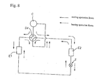
- Fig. 8 illustrates an example of a cooling/heating cycle of an air conditioner using the selector valve.
- a compressor C For this cycle, a compressor C, a selector valve SV, heat exchangers E 1 and E 2 , and an electronic linear control valve T are connected.
- the refrigerant as used for the cooling operation flows through the compressor C, the selector valve SV, an outdoor heat exchanger E1, the electronic linear control valve T, and an indoor heat exchanger E2 in this order.
- the refrigerant then completes the circulation by returning through the selector valve SV to the compressor C.
- the refrigerant as used for the heating flows through the compressor C, the selector valve SV, the indoor heat exchanger E 2 , the electronic linear control valve T, and the outdoor heat exchanger El in this order.
- the refrigerant then completes the circulation by returning through the selector valve SV to the compressor C.
- the proposed art comprises an electromagnet provided on a valve main body, a valve seat mounted at the bottom of the main body, and a rotatable valve provided in the valve main body.
- the valve seat has, at given angles and spacing, a discharge pressure passage which introduces the discharge pressure of the compressor, a suction pressure passage which introduces the suction pressure, a passage hole for an indoor heat exchanger and a passage hole for an outdoor heat exchanger, which lead to the respective heat exchangers.
- the rotatable valve is formed from plastic magnet, and has a guide hole which may alternately connect the discharge pressure passage to one of the two passage holes, and a connecting groove which may alternately connect the suction pressure passage to one of the two passage holes.
- the discharge pressure passage is provided with a conduit whose leading end extrudes to the end of the guide hole. The extruding part of the conduit makes contact with the end of the guide hole, thereby serving as a stopper to limit the rotation of the valve.
- a four-way selector valve comprising (a) a valve seat which has a discharge pressure passage, a suction pressure passage, a passage hole for an indoor heat exchanger and a passage hole for an outdoor heat exchanger, (b) a freely sliding main valve which switches to one of the passage holes, (c) a valve chest which is formed in the main body of the valve by covering all of the passage holes with the main valve, (d) an auxiliary valve which opens/closes the suction pressure passage using magnetic force, and (e) a spring which connects the auxiliary valve and the main valve; wherein the diameter of the discharge pressure passage is smaller than that of the suction pressure passage (see, e.g., Japanese Examined Patent Publication No. 1-32389/1989).
- the rotatable valve or a four-way selector valve disclosed in the Japanese Utility Model Registration No. 2523031 uses switching between the flow paths for refrigerant via the discharge pressure passage, the passage hole, the suction pressure passage, and the other passage hole, which is performed inside and outside the main valve.
- the suction pressure occurs inside the main valve, while the discharge pressure occurs at high pressure outside the main valve. Therefore, there is a pressure difference across the main valve, which tends to cause the switching operation to become heavy.
- this four-way selector valve no particular consideration is given to make easier and quicker the switching operation between the flow paths for refrigerant.
- the four-way selector valve uses switching between flow paths for refrigerant by the main valve after eliminating the pressure difference across the main body of the valve. Since the main valve is rotated by the elongation and compression of elastic members, no special consideration is given to make quicker the switching operation between the flow paths for refrigerant, nor to the reliability of the four-way selector valve.
- the object of the invention is to provide a four-way selector valve which provides easier and quicker switching between flow paths for refrigerant, assures higher reliability, and allows itself to be configured more simply to decrease product cost.
- the four-way selector valve of the present invention basically comprises a motor which has a stator and a rotor, a case, and a main body.
- the main body includes a main valve and a valve seat, both of which are arranged in a valve chest within the case.
- the valve seat has a suction pressure passage led to a suction port of a compressor, and a discharge pressure passage led to a discharge port of the compressor.
- the valve seat further has two passage holes led to indoor and outdoor heat exchangers, respectively.
- the main valve has a connecting part which selectively connects the suction pressure passage to one of the two passage holes, and a pressure equalization orifice which links the connecting part and the valve chest.
- the rotor comprises a rotor sleeve having the auxiliary valve which opens or closes the pressure equalization orifice in order to transfer pressure.
- the operating pin moves the position of the main valve.
- the rotor of the motor rotates the auxiliary valve on the main valve and slides the main valve on the valve seat via the operating pin.
- the four-way selector valve of the invention which is configured as described above, may have, on the main valve, an auxiliary valve which moves pressure inside and outside the main valve.
- the rotation of the rotor may turn the auxiliary valve to rotate on the main valve, thereby to open or close the pressure equalization orifice so that pressure may move between the connecting part and the valve chest.
- the main valve slides on the valve seat in the valve chest. Therefore, the number of operating parts may be reduced, the configuration of the selector valve may be made simpler, the reliability of the inverter valve can be improved, and the switching operation between flow paths for refrigerant can be performed easily and quickly by the main valve.
- the auxiliary valve may be a relief valve, located between the rotor and the main valve, retained to the rotor sleeve, and mounted on the main valve so that it may slide thereon.
- the rotor sleeve may be equipped with a supporting shaft concentric to the rotational center of the main valve, and the operating pin may be retained to the rotor sleeve and turns the main valve while rotating together with the rotor.
- the supporting shafts at the top and bottom of the rotor sleeve may be provided with elastic members which energize or press the auxiliary valve and the main valve toward the valve seat.
- the valve seat may be provided with a main valve stopper which limits the rotation range of the main valve and that the main valve has a stopper contactor which makes contacts with the main valve stopper. The position of switching by the main valve between the flow paths for refrigerant can securely be regulated, and the production cost for the main valve can be reduced if a same material is used for the stopper contactor and the main valve.
- Still another embodiment of the four-way selector valve according to the invention is that either the main valve stopper or the stopper contactor comprises a magnet and that the other consists of a magnetic substance.
- the switching position for the flow paths for refrigerant can be more securely retained by the magnetic force of the main valve stopper or the stopper contactor, and the vibration resistance of the four-way selector valve can be further improved.
- Another embodiments of the four-way selector valve according to the invention is that at least one of the main valve, the auxiliary valve, and the valve seat may be coated with lubricative anodized aluminum film, which improves the lubricative property in sliding the main valve or the auxiliary valve. As a result, the sliding friction may become so low that the stable operation can be performed.
- Fig. 1 is a perspective illustration for appearance of the four-way selector valve in the first embodiment of the invention.
- Fig. 2 is an exploded perspective illustration for the four-way selector valve as shown in Fig. 1.
- Fig. 3 is a vertical sectional view of the four-way selector valve as shown in Fig.1.
- Fig. 4A is a sectional view of the four-way selector valve, taken along the line 4A-4A of Fig.3.
- Fig. 4B is a sectional view of the four-way selector valve, taken along the line 4B-4B of Fig. 3.
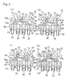
- Figs. 5A through 5D are top views illustrating the operation of the four-way selector valve as shown in Fig. 1.
- Figs. 6A through 6D are vertical sectional views of the four-way selector valve as shown in Fig. 1.
- Fig. 7 is a vertical sectional view of the four-way selector valve in another embodiment of the invention.
- Fig. 8 is a diagram of cyclic flow for air-conditioning.
- Figs. 1 through 4A and 4B illustrate an embodiment of the four-way selector valve according to the invention.
- Fig. 1 is a perspective view of appearance of the four-way selector valve according to the embodiment.
- Fig. 2 is a perspective view of the four-way selector valve.
- Fig. 3 is a vertical sectional view of the four-way selector valve.
- Figs. 4A and 4B consist of sectional views of the four-way selector valve as illustrated in Fig. 3.
- the four-way selector valve 100 in the illustrated embodiment comprises a motor 10 equipped with a stepping motor, and a main body 50 equipped with a main valve 70.
- a main valve 70 rotates on a seat valve 80 when the stepping motor is turned on, so that the flow path for refrigerant is switched.
- the motor 10 comprises a stator 20 and a rotor 40.
- the stator 20 is provided with a stator coil 21 and a yoke 22 which are vertically housed therein.
- a cable 23 consisting of bundled lead wires and a connector 24 provided on the outer surface of the stator 20 are connected to the stator coil 21.
- a mount 25 of given height is provided on the top of the stator 20.
- a snapper 26 made of a metal sheet is retained to the mount with a screw 27.
- a relatively thin, spherical part 26a of the snapper 26 engages into one of four dimples 32 which are provided at given angles (90 degrees each) and spacing on the circumferential surface of a upper cylindrical part 31 of a case 30 which will be described later. This prevents the stator 20 from rotating and slipping off the upper cylindrical part 31.
- the spherical part 26a engages with one of the dimples 32, they fit to each other on the same surface.
- the rotor 40 comprises a rotor sleeve 41, an upper supporting shaft 42 which is inserted into the center of the top of the rotor sleeve 41, and a lower supporting shaft 43 which is inserted into the center of the bottom of the rotor sleeve 41.
- the rotor sleeve 41 is equipped with a magnet 48 on its circumferential surface.
- the upper end of the upper supporting shaft 42 makes point-contact with the peak of the inner spherical surface of the upper cylindrical part 31.
- the upper supporting shaft 42 is provided with an upper coil spring 44 which is an elastic member to energize or press a rotor sleeve 41 and an auxiliary valve 61, which is a relief valve and will be described later, toward a main valve 70 via a spring holder 45, which is an integral part of the upper supporting shaft 42, and others.
- the lower supporting shaft 43 is provided with a lower coil spring 46 which is an elastic member to energize or press the main valve 70 toward a valve seat 80 (i.e., to energize or press the rotor sleeve 41 upward) via a spring holder 47 and others.
- the energizing force of the upper coil spring is larger than that of the lower coil spring.
- the main body 50 comprises a case 30, which is a can, the main valve, the valve seat 80, and a group of conduits 90.
- the case 30 according to this embodiment consists of an upper cylindrical part 31 with a spherical top, a lower cylindrical part 33 having larger diameter than that of the upper cylindrical part 31.
- the lower cylindrical part extends from the bottom of the upper cylindrical part 31 and forms a single unit therewith, and a flange 35 which outwardly extends from the bottom of the lower cylindrical part 33.
- the upper cylindrically part 31 is covered with the rotor 40, and the rotor 40 is covered with the upper cylindrical part 31.
- the lower cylindrical part 33 covers the valve seat 80 which has a flange 89 at its bottom.
- the flange 35 and the flange 89 are coupled with bolts 69 so that the case 30 and the valve seat 80 are retained as a single unit.
- the main valve 70 is accommodated within the lower cylindrical part 33 of the case 30, and placed on the top of the valve seat 80 so as to allow the main valve 70 to slide thereon.
- the internal part of the lower cylindrical part 33 is formed as a valve chest 73.
- the auxiliary valve 61 and a relatively cylindrical operating pin 64 are provided on the top of the main valve 70.
- the auxiliary valve 61 opens/closes a pressure equalization orifice 77 in the main valve 70, thereby making connection/disconnection with the valve chest 73 in the case 30 so that pressure can be moved.
- the operating pin 64 rotates together with the rotor 40, thereby sliding the main valve 70.
- the auxiliary valve 61 and the operating pin 64 are retained to respective positions appropriately separated from a straight line passing through the axial center of the lower supporting shaft 43 of the rotor 40.
- a stator coil 21 is excited through a cable 23 and a connector 24.
- the main valve 70 is rotated on the valve seat 80 by the operating pin 64 via the rotor 40. Accordingly, switching between the flow paths for refrigerant, which will be described later, is performed.
- the auxiliary valve 61 rotates on the main valve 70 via the rotor 40, thereby opening/closing the pressure equalization orifice.
- the main valve forms a roughly fan-shaped part with a central part 72 which is connected to the lower supporting shaft 43, and a top surface 75 extending outward from the central part 72.
- a connecting hole 71 is provided at the central part 72 so that the lower supporting shaft can be inserted thereinto.
- the main valve 70 has pin contactors 78A and 79A provided symmetrically on its right and left surfaces.
- stopper contactors 78a and 79a which make contact with main valve stopper 86 provided on the valve seat 80, are located on the lower parts of the pin contactors 78A and 79A.
- the stopper contactors 78a and 79a are shaped so as to provide the optimal control curve, control line, or the like, which assures that the main valve 70 is rotated in accordance with the rotational angle per unit pulse of the stepping motor via the operating pin 64 and that the motion of the main valve 70 is regulated by making contact with the main valve stopper 86.
- the main valve 70 and the valve seat 80 in this embodiment may be configured to use magnets such as a ferrite magnet for the stopper contactors 78a and 79a thereof, and using a magnetic substance of iron or the like for the main valve stopper 86.
- magnets such as a ferrite magnet for the stopper contactors 78a and 79a thereof
- a magnetic substance of iron or the like for the main valve stopper 86.
- the contact between the stopper contactors 78a or 79a and the main valve stopper 86 is maintained with magnetic force.
- the intensity of the magnetic force is set, as appropriate, to a smaller value than the rotational force of the motor 10.
- the stopper contactors 78a and 79a are molded by insert molding. If the central part 72 and the top surface 75 are made of metal such as aluminum, the stopper contactors 78a and 79a may be bonded.
- the stopper contactors 78a and 79b may be magnetic bodies, and the main valve stopper 86 may be made of a magnet.
- the main valve 70 internally provides a connecting part 74 which connects to one of a suction pressure passage 82 in the valve seat 80, a passage hole 84 for the outdoor heat exchanger, and a passage hole 85 for the indoor heat exchanger, and a pressure equalization orifice 77 which connects the connecting part 74 and the valve chest 73.
- the auxiliary valve 61 comprises a rotor press-fitting part 62 and a blocking part 63 for the pressure equalization orifice.
- the rotor press-fitting part 62 is press-fit and retained to the bottom of the rotor 40.
- the blocking part 63 for the pressure equalization orifice makes contact with the top of the main valve 70. Both the pressure of refrigerant in the valve chest 73 and that for refrigerant in the connecting part 74 are given to the top and bottom of the main valve 70.
- the top of the valve seat 80 is flat, making contact with the bottom of the main valve 70.
- a bolt 69 is inserted into a bolt hole 87 in a flange 89 from the bottom of the valve seat and a bolt hole 34 in a flange 35 of the case 30, and then tightened.
- the central part has a press-fitting hole 81 in which the lower supporting shaft 43 is press-fit and retained. In given positions radially separated from the center of the lower supporting shaft 43, there are a suction pressure passage 82 which introduces the suction pressure of the compressor, a discharge pressure passage 83 which introduces the discharge pressure, a passage hole 84 for the outdoor heat exchanger, and a passage hole 85 for the indoor heat exchanger.
- a main valve stopper 86 which is shaped like a cylinder and used to regulate the rotational position of the main valve 70, is secured.
- the case 30 and the valve seat 80 are coupled and retained with an O-ring, making the valve chest 73 airtight.
- the suction pressure passage 82 and the discharge pressure passage are symmetrically provided with respect to the lower supporting shaft 43.
- the passage hole 84 for the outdoor heat exchanger and the passage hole 85 for the indoor heat exchanger are symmetrically provided with respect to the lower supporting shaft 43 at given angles from the suction pressure passage 82 and the discharge pressure passage 83 .
- the main valve stopper 86 is provided in an appropriate position along the straight line between the suction pressure passage 82 and the discharge pressure passage 83, and located between the lower supporting shaft 43 and the discharge pressure passage 83.
- the group of conduits 90 consists of four conduits, namely, a suction pressure conduit 92 which is connected to the suction pressure passage 82, a discharge pressure conduit 93 which is connected to the discharge pressure passage 83, a conduit 94 for the outdoor heat exchanger, which is connected to the passage hole 84 for the outdoor heat exchanger, and a conduit 95 for the indoor heat exchanger, which is connected to the passage hole 85 for the indoor heat exchanger.
- Each of the conduits is connected and retained to the bottom of the valve seat 80.
- At least one of the main valve 70, the auxiliary valve 61, and the valve seat 80 according to this embodiment may be coated with lubricative anodized aluminum film.
- lubricative anodized aluminum film e.g., "KASHIMA COAT" (product name: Miyaki Co., Ltd.) is used as follows:
- the main valve 70 is made of aluminum. This aluminum is anodized to create a hard alumina layer. Molybdenum disulfide is electrolytically deposited. Coating this lubricative anodized aluminum film improves the lubricative property of the main valve 70.
- a blocking portion of the pressure equalization orifice 63 on the auxiliary valve 61 and the valve seat 80 are made of aluminum.
- the lubricative anodized aluminum film is coated over them, enabling further improvement of the lubricative property between the auxiliary valve 61 and the main valve 70 and that between the main valve 70 and the valve seat 80.
- lubricative anodized aluminum film not only the "KASHIMA COAT,” but also "UNIMITE” (product name: Ueda Anodized Aluminum Film Industries Co., Ltd.) or “TOUGHMITE” (product name: Ueda Anodized Aluminum Film Industries Co., Ltd.) may similarly be used for at least one of the main valve, the auxiliary valve, and the valve seat.
- "UNIMITE” product name: Ueda Anodized Aluminum Film Industries Co., Ltd.
- TOUGHMITE product name: Ueda Anodized Aluminum Film Industries Co., Ltd.
- Coating the lubricative anodized aluminum film decreases the sliding friction between the auxiliary valve and the main valve and that between the main valve and the valve seat, thereby making the operation stable.
- the improved lubricative property enables the operation of the four-way selector valve at low torque.
- the motor can be downsized.
- Figs. 5A through 5D and Figs. 6A through 6D illustrate the operation of the four-way selector valve 100 according to its internal structure.
- Figs. 5A through 5D illustrate the same operation condition as shown in Figs. 6A through 6D respectively.
- Figs. 5A and 6A illustrates the setup for the cooling operation, wherein the suction pressure conduit 92 and the conduit 95 for the indoor heat exchanger are connected via the connecting part 74 of the main valve 70, and wherein the discharge pressure conduit 93 and the conduit 94 for the outdoor heat exchanger are connected to the outside of the main valve 70, i.e., to the valve chest 73.
- the four-way selector valve 100 uses the auxiliary valve 61, which is a relief valve, to switch the flow path for refrigerant from this state. This is intended to balance the pressure in the valve chest 73 with that in the connecting part, and to rotate the main valve 70 after eliminating the force which press the main valve 70.
- the suction pressure conduit 92 and the conduit 94 for the outdoor heat exchanger reversibly rotate the stepping motor after they has been connected in the connecting part 74. This continues to rotate the operating pin 64 and the auxiliary valve 61 counterclockwise as shown in Figs. 5D and 6D until the blocking part 63 for the pressure equalization orifice on the auxiliary valve 61 closes the pressure equalization orifice 77 in the main valve 70.
- the pressure equalization orifice 77 closed by the blocking part 63 for the pressure equalization orifice on the auxiliary valve should be released, and then the main valve 70 should be rotated until the operating pin 64 makes contact with the contactor 78A and the stopper contactor 79a makes contact with the main valve stopper 86.
- the embodiment according to the invention provides the following function using the above configuration:
- the main valve is rotated on the valve seat 80. Therefore, after the pressure balance between the valve chest 73 and the connecting part 74 has been acquired, the refrigerant flow can be switched. This means that the flow paths for refrigerant can be switched more easily and quickly than in the case where the main valve is rotated using elastic members. In addition, the reliability of the four-way selector valve can be improved.
- the auxiliary valve 61 is positioned between the rotor 40 and the main valve 70, mounted on the main valve 70, and pressed by the upper coil spring 44 toward the main valve 70. It rotates together with the rotor 40 and functions as a relief valve which eliminates a pressure difference between the connecting part 74 and the valve chest 73. Therefore, the flow path for refrigerant can be switched promptly, and product cost for the four-way selector valve can be reduced by decreasing the number of movable parts.
- the stopper contactors 78a and 79a, and the main valve stopper 86 maintain the contact state by their own magnetic force, the switching position of the main valve 70 with respect to the valve seat 80 can securely be held against vibrations. Thus, the reliability of the four-way selector valve 100 can be further improved.
- Fig. 7 is a sectional view illustrating another embodiment according to the invention.
- the four-way selector valve as generally represented by code 200 has the same configuration as that of the previously described four-way selector valve. Therefore, the same parts are assigned the same code and the description thereof is omitted.
- a supporting shaft 140 which supports a rotor 140 comprises a single shaft.
- the supporting shaft 140 is press-fit into a press-fitting hole 81 in a valve seat 80 and then retained.
- a bearing 148 is located in two places, the top and bottom of a rotor sleeve 41, between the supporting shaft 140 and the rotor sleeve 41.
- a snap ring 141 and a coil spring 142 are fit to the end of the supporting shaft 140 opposite to the side of the valve seat 80.
- the coil spring 142 energizes a rotor 140 toward the valve seat 80 via a spring holder ring 143.
- a snap ring 145 and a coil spring 146 are fit between the rotor sleeve 41 of the supporting shaft 140 and the main valve 70.
- the coil spring 146 energizes the main valve 70 toward the valve seat 80 via a spring holder ring 147.
- the four-way selector valve 200 further decreases the number of parts, requires no shaft alignment as opposed to the case where two supporting shafts are used, and has a simpler structure. In addition, the rotational accuracy of the rotor is improved.
- the four-way selector valve according this invention has the auxiliary valve provided on the top of the main valve. After the pressure balance between the valve chest and the connecting part of the main valve has been acquired, the positional switching of the main valve is performed. Therefore, the switching operation between the flow paths for refrigerant can be improved so that it becomes easier and quicker. At the same time, the product cost for the selector valve can be reduced.
Landscapes
- Engineering & Computer Science (AREA)
- General Engineering & Computer Science (AREA)
- Mechanical Engineering (AREA)
- Physics & Mathematics (AREA)
- Fluid Mechanics (AREA)
- Thermal Sciences (AREA)
- Multiple-Way Valves (AREA)
- Electrically Driven Valve-Operating Means (AREA)
Abstract
Description
Claims (7)
- A four-way selector valve comprising a motor having a stator and a rotor, a case, and a main body including a main valve and a valve seat, the main valve and the valve seat are arranged in a valve chest within the case;characterized in that the valve seat comprises a suction pressure passage a discharge pressure passage and first and second passage holes, the suction pressure passage is connected to a suction port of a compressor, the discharge pressure passage is connected to a discharge port of the compressor, the first and second passage holes are connected to indoor and outdoor heat exchangers respectively;the main valve comprises a connecting part which leads the suction pressure passage to one of the first and second passage holes and a pressure equalization orifice which links the connecting part and the valve chest;the rotor comprises a rotor sleeve comprising a auxiliary valve and an operating pin, the auxiliary valve opens or closes the pressure equalization orifice to transfer pressure, and the operating pin moves the position of the main valve; andthe rotor rotates the auxiliary valve to slide the main valve on the valve seat via the operating pin.
- The four-way selector valve according to claim 1,
characterized in that the auxiliary valve is a relief valve located between the rotor and the main valve, retained to the rotor sleeve, and slidably mounted on the main valve. - The four-way selector valve according to claim 1 or 2,
characterized in that the rotor sleeve comprises a supporting shaft which is concentric to rotational center of the main valve, the operating pin retained to the rotor sleeve rotates the main valve according to the rotation of the rotor. - The four-way selector valve according to claim 3,
characterized in that the supporting shaft comprises an elastic member which presses the auxiliary valve and the main valve onto the valve seat. - The four-way selector valve according to claim 1 or 4,
characterized in that the valve seat comprises a main valve stopper which regulates the turning range of the main valve, and the main valve comprises a stopper contactor which makes contact with the main valve stopper. - The four-way selector valve according to claim 5,
characterized in that at least one of the main valve stopper and the stopper contactor comprises one of a magnet and a magnetic substance. - A four-way selector valve according to claim 1,
characterized in that at least one of the main valve, the valve seat, and the auxiliary valve is coated with lubricative anodized aluminum film.
Applications Claiming Priority (8)
| Application Number | Priority Date | Filing Date | Title |
|---|---|---|---|
| JP2000033730 | 2000-02-10 | ||
| JP2000033730 | 2000-02-10 | ||
| JP2000056666A JP2001295951A (en) | 2000-02-10 | 2000-03-02 | Four-way selector valve |
| JP2000056666 | 2000-03-02 | ||
| JP2000125465 | 2000-04-26 | ||
| JP2000125465 | 2000-04-26 | ||
| JP2000330377A JP4315589B2 (en) | 2000-04-26 | 2000-10-30 | Four-way selector valve |
| JP2000330377 | 2000-10-30 |
Publications (2)
| Publication Number | Publication Date |
|---|---|
| EP1124082A1 true EP1124082A1 (en) | 2001-08-16 |
| EP1124082B1 EP1124082B1 (en) | 2006-12-06 |
Family
ID=27481025
Family Applications (1)
| Application Number | Title | Priority Date | Filing Date |
|---|---|---|---|
| EP20010103096 Expired - Lifetime EP1124082B1 (en) | 2000-02-10 | 2001-02-09 | Four-way selector valve |
Country Status (5)
| Country | Link |
|---|---|
| US (1) | US6505647B2 (en) |
| EP (1) | EP1124082B1 (en) |
| KR (1) | KR100758366B1 (en) |
| CN (1) | CN1244760C (en) |
| DE (1) | DE60124966T2 (en) |
Cited By (4)
| Publication number | Priority date | Publication date | Assignee | Title |
|---|---|---|---|---|
| EP1593889A4 (en) * | 2003-02-14 | 2007-12-19 | Saginomiya Seisakusho Inc | ELECTRICALLY ACTUATED TILTING VALVE |
| DE102016203761A1 (en) | 2016-03-08 | 2017-09-14 | BSH Hausgeräte GmbH | Refrigerating appliance and rotary valve valve for it |
| DE102017129991A1 (en) * | 2017-12-14 | 2019-06-19 | Minebea Mitsumi Inc. | Fluid distribution device, in particular water distribution device |
| PL131507U1 (en) * | 2022-06-24 | 2023-12-27 | G20 Engineering S.R.L. | Four-way valve |
Families Citing this family (27)
| Publication number | Priority date | Publication date | Assignee | Title |
|---|---|---|---|---|
| DE10310662A1 (en) * | 2003-03-12 | 2004-09-23 | Ksb Aktiengesellschaft | Fitting for switchover of fluid path, has flow divisor with by-passes, and rotary disk-shaped steering elements that respectively sealing the axial face of the corresponding by-pass |
| KR100465554B1 (en) * | 2004-09-14 | 2005-01-13 | 윤상혁 | Device for opening and closing electronic valve for controlling multi room |
| US7895850B2 (en) * | 2005-04-15 | 2011-03-01 | Comforture, L.P. | Modulating proportioning reversing valve |
| KR100744263B1 (en) * | 2005-12-28 | 2007-07-30 | 동부일렉트로닉스 주식회사 | Pattern monitoring method in semiconductor chemical mechanical polishing equipment |
| CN101230928B (en) * | 2007-01-26 | 2010-09-22 | 浙江三花制冷集团有限公司 | Electric switching valve and refrigerator refrigerating cycle device |
| CN101270826B (en) * | 2007-03-19 | 2010-04-21 | 浙江三花制冷集团有限公司 | Electric switching valve |
| WO2009147932A1 (en) * | 2008-06-02 | 2009-12-10 | 株式会社鷺宮製作所 | Flow path selector valve |
| JP5175144B2 (en) * | 2008-08-07 | 2013-04-03 | 株式会社不二工機 | Four-way switching valve disc |
| JP5385393B2 (en) * | 2008-09-05 | 2014-01-08 | ダンフォス アクチ−セルスカブ | Expansion valve with force balancing mechanism |
| JP5389570B2 (en) * | 2009-08-25 | 2014-01-15 | 株式会社不二工機 | Multi-way selector valve |
| CN101825121B (en) * | 2010-04-09 | 2012-06-27 | 山东交通学院 | Stain-resistant and high-pressure-resistant four-way valve capable of loading and unloading |
| JP5611658B2 (en) * | 2010-05-12 | 2014-10-22 | 株式会社不二工機 | Multi-way selector valve |
| CN102155556B (en) * | 2010-07-09 | 2012-12-26 | 雅鼎卫浴股份有限公司 | Multi-functional concealed installation switchover valve body |
| JP5611699B2 (en) * | 2010-07-28 | 2014-10-22 | 株式会社不二工機 | Multi-way selector valve |
| JP5077464B1 (en) * | 2011-06-30 | 2012-11-21 | ダイキン工業株式会社 | Refrigerant flow path switching valve and air conditioner using the same |
| JP5606511B2 (en) * | 2011-11-25 | 2014-10-15 | 浙江三花股▲分▼有限公司 | Electric switching valve |
| US10018387B2 (en) * | 2012-03-23 | 2018-07-10 | Lennox Industries, Inc. | Reversing valve |
| JP5907506B2 (en) * | 2013-03-22 | 2016-04-26 | 株式会社鷺宮製作所 | Rotary valve device |
| JP6046076B2 (en) * | 2014-04-10 | 2016-12-14 | 株式会社鷺宮製作所 | Valve body for flow path switching valve |
| EP3309432B1 (en) * | 2015-05-14 | 2020-06-17 | Zhejiang Sanhua Climate and Appliance Controls Group Co. Ltd. | Reversing valve and cooling system having same |
| US10422433B2 (en) * | 2015-11-20 | 2019-09-24 | Mitsubishi Electric Corporation | Valve apparatus and air conditioning apparatus |
| WO2018070761A1 (en) * | 2016-10-11 | 2018-04-19 | 엘지전자 주식회사 | Four-way valve for switching refrigerant channel |
| CN109899334A (en) * | 2019-02-19 | 2019-06-18 | 南京南瑞水利水电科技有限公司 | A kind of hydrogovernor rotary valve main control valve |
| WO2021067346A1 (en) * | 2019-10-03 | 2021-04-08 | Oceaneering International, Inc | Isolation valve for fluid flow regulation |
| CN112283384B (en) * | 2020-10-28 | 2023-04-07 | 凯喜姆阀门有限公司 | Valve rod blowout prevention ball outlet valve |
| CN115674992B (en) * | 2021-07-28 | 2026-04-17 | 浙江三花汽车零部件有限公司 | Fluid control components and thermal management systems |
| CN116734003A (en) * | 2022-03-04 | 2023-09-12 | 浙江三花智能控制股份有限公司 | Electromagnetic reversing valve |
Citations (5)
| Publication number | Priority date | Publication date | Assignee | Title |
|---|---|---|---|---|
| US3964517A (en) * | 1975-01-14 | 1976-06-22 | Dickenson Harvard G | Four way diverter valve |
| US4381798A (en) * | 1980-02-29 | 1983-05-03 | Carrier Corporation | Combination reversing valve and expansion device for a reversible refrigeration circuit |
| US4825908A (en) * | 1987-04-28 | 1989-05-02 | Yokohama Aeroquip Corporation | Four-way valve |
| EP0702176A1 (en) * | 1994-09-16 | 1996-03-20 | Ranco Incorporated of Delaware | Rotary reversing valve |
| US5944299A (en) * | 1996-08-28 | 1999-08-31 | Fuji Injector Corporation | Rotation switching mechanism in rotary type switching valve |
Family Cites Families (3)
| Publication number | Priority date | Publication date | Assignee | Title |
|---|---|---|---|---|
| US330861A (en) * | 1885-11-17 | Valve | ||
| US2855000A (en) * | 1955-02-16 | 1958-10-07 | Robertshaw Fulton Controls Co | Reverse flow valve |
| JP3383442B2 (en) * | 1994-11-04 | 2003-03-04 | 日本ランコ株式会社 | Four-way valve |
-
2001
- 2001-02-09 EP EP20010103096 patent/EP1124082B1/en not_active Expired - Lifetime
- 2001-02-09 DE DE2001624966 patent/DE60124966T2/en not_active Expired - Lifetime
- 2001-02-09 US US09/779,671 patent/US6505647B2/en not_active Expired - Fee Related
- 2001-02-09 CN CNB011036907A patent/CN1244760C/en not_active Expired - Fee Related
- 2001-02-09 KR KR1020010006418A patent/KR100758366B1/en not_active Expired - Fee Related
Patent Citations (7)
| Publication number | Priority date | Publication date | Assignee | Title |
|---|---|---|---|---|
| US3964517A (en) * | 1975-01-14 | 1976-06-22 | Dickenson Harvard G | Four way diverter valve |
| US4381798A (en) * | 1980-02-29 | 1983-05-03 | Carrier Corporation | Combination reversing valve and expansion device for a reversible refrigeration circuit |
| US4825908A (en) * | 1987-04-28 | 1989-05-02 | Yokohama Aeroquip Corporation | Four-way valve |
| EP0702176A1 (en) * | 1994-09-16 | 1996-03-20 | Ranco Incorporated of Delaware | Rotary reversing valve |
| US5507315A (en) * | 1994-09-16 | 1996-04-16 | Ranco Incorporated Of Delaware | Reversing valve and method |
| US5878781A (en) * | 1994-09-16 | 1999-03-09 | Ranco Incorporated Of Delaware | Reversing valve and method |
| US5944299A (en) * | 1996-08-28 | 1999-08-31 | Fuji Injector Corporation | Rotation switching mechanism in rotary type switching valve |
Cited By (5)
| Publication number | Priority date | Publication date | Assignee | Title |
|---|---|---|---|---|
| EP1593889A4 (en) * | 2003-02-14 | 2007-12-19 | Saginomiya Seisakusho Inc | ELECTRICALLY ACTUATED TILTING VALVE |
| DE102016203761A1 (en) | 2016-03-08 | 2017-09-14 | BSH Hausgeräte GmbH | Refrigerating appliance and rotary valve valve for it |
| DE102017129991A1 (en) * | 2017-12-14 | 2019-06-19 | Minebea Mitsumi Inc. | Fluid distribution device, in particular water distribution device |
| PL131507U1 (en) * | 2022-06-24 | 2023-12-27 | G20 Engineering S.R.L. | Four-way valve |
| PL74344Y1 (en) * | 2022-06-24 | 2026-04-13 | G20 Engineering S.R.L. | Four-way valve |
Also Published As
| Publication number | Publication date |
|---|---|
| CN1244760C (en) | 2006-03-08 |
| US6505647B2 (en) | 2003-01-14 |
| US20010013369A1 (en) | 2001-08-16 |
| KR100758366B1 (en) | 2007-09-14 |
| CN1308197A (en) | 2001-08-15 |
| DE60124966T2 (en) | 2007-09-20 |
| EP1124082B1 (en) | 2006-12-06 |
| DE60124966D1 (en) | 2007-01-18 |
| KR20010082103A (en) | 2001-08-29 |
Similar Documents
| Publication | Publication Date | Title |
|---|---|---|
| US6505647B2 (en) | Four-way selector valve | |
| KR100476520B1 (en) | Rotary flow-path exchanging valve | |
| JP4981663B2 (en) | Switching valve | |
| CN1329685C (en) | Valve device | |
| CN1388876A (en) | Motor-operated selector valve and refrigerating cycle device of refrigerator-freezer | |
| US6983760B2 (en) | Vaned spool type directional control valve and four-way reversible valve for cooling cycle system using the same | |
| CN100487289C (en) | Electric valve | |
| JP4315589B2 (en) | Four-way selector valve | |
| JP2002276827A (en) | Control valve | |
| JP2001295951A (en) | Four-way selector valve | |
| JP2001343076A (en) | Control valve | |
| JP5404456B2 (en) | Multi-way selector valve | |
| US6546841B2 (en) | Swash plate compressor and piston therefor | |
| JPH09229214A (en) | 4-way switching valve | |
| JP2001343077A (en) | Control valve | |
| US6508633B2 (en) | Swash plate type compressor of variable capacity type | |
| JP4454138B2 (en) | Four-way selector valve with accumulator | |
| US5944299A (en) | Rotation switching mechanism in rotary type switching valve | |
| JPH06281024A (en) | Four-way selector valve | |
| JP4009091B2 (en) | Four-way selector valve | |
| JPH116573A (en) | Four way valve suppressing switching shock | |
| JPH11141707A (en) | Rotary type flow switching valve | |
| JPH10300279A (en) | Channel-switching device of high/low-pressure gas in heating-cooling combination device | |
| JP4541242B2 (en) | Compressor with flow path switching valve and air conditioner for air conditioning | |
| JP3105788U (en) | Valve structure, multi-function operation valve of this valve structure |
Legal Events
| Date | Code | Title | Description |
|---|---|---|---|
| PUAI | Public reference made under article 153(3) epc to a published international application that has entered the european phase |
Free format text: ORIGINAL CODE: 0009012 |
|
| AK | Designated contracting states |
Kind code of ref document: A1 Designated state(s): DE ES FR GB IT NL |
|
| AX | Request for extension of the european patent |
Free format text: AL;LT;LV;MK;RO;SI |
|
| 17P | Request for examination filed |
Effective date: 20010901 |
|
| AKX | Designation fees paid |
Free format text: DE ES FR GB IT NL |
|
| GRAP | Despatch of communication of intention to grant a patent |
Free format text: ORIGINAL CODE: EPIDOSNIGR1 |
|
| GRAS | Grant fee paid |
Free format text: ORIGINAL CODE: EPIDOSNIGR3 |
|
| GRAA | (expected) grant |
Free format text: ORIGINAL CODE: 0009210 |
|
| AK | Designated contracting states |
Kind code of ref document: B1 Designated state(s): DE ES FR GB IT NL |
|
| PG25 | Lapsed in a contracting state [announced via postgrant information from national office to epo] |
Ref country code: NL Free format text: LAPSE BECAUSE OF FAILURE TO SUBMIT A TRANSLATION OF THE DESCRIPTION OR TO PAY THE FEE WITHIN THE PRESCRIBED TIME-LIMIT Effective date: 20061206 |
|
| REG | Reference to a national code |
Ref country code: GB Ref legal event code: FG4D |
|
| REF | Corresponds to: |
Ref document number: 60124966 Country of ref document: DE Date of ref document: 20070118 Kind code of ref document: P |
|
| PG25 | Lapsed in a contracting state [announced via postgrant information from national office to epo] |
Ref country code: ES Free format text: LAPSE BECAUSE OF FAILURE TO SUBMIT A TRANSLATION OF THE DESCRIPTION OR TO PAY THE FEE WITHIN THE PRESCRIBED TIME-LIMIT Effective date: 20070317 |
|
| ET | Fr: translation filed | ||
| NLV1 | Nl: lapsed or annulled due to failure to fulfill the requirements of art. 29p and 29m of the patents act | ||
| PLBE | No opposition filed within time limit |
Free format text: ORIGINAL CODE: 0009261 |
|
| STAA | Information on the status of an ep patent application or granted ep patent |
Free format text: STATUS: NO OPPOSITION FILED WITHIN TIME LIMIT |
|
| 26N | No opposition filed |
Effective date: 20070907 |
|
| PGFP | Annual fee paid to national office [announced via postgrant information from national office to epo] |
Ref country code: IT Payment date: 20080227 Year of fee payment: 7 |
|
| REG | Reference to a national code |
Ref country code: GB Ref legal event code: 746 Effective date: 20090408 |
|
| PG25 | Lapsed in a contracting state [announced via postgrant information from national office to epo] |
Ref country code: IT Free format text: LAPSE BECAUSE OF NON-PAYMENT OF DUE FEES Effective date: 20080209 |
|
| PGFP | Annual fee paid to national office [announced via postgrant information from national office to epo] |
Ref country code: FR Payment date: 20110218 Year of fee payment: 11 Ref country code: DE Payment date: 20110208 Year of fee payment: 11 |
|
| PGFP | Annual fee paid to national office [announced via postgrant information from national office to epo] |
Ref country code: GB Payment date: 20110209 Year of fee payment: 11 |
|
| GBPC | Gb: european patent ceased through non-payment of renewal fee |
Effective date: 20120209 |
|
| REG | Reference to a national code |
Ref country code: FR Ref legal event code: ST Effective date: 20121031 |
|
| REG | Reference to a national code |
Ref country code: DE Ref legal event code: R119 Ref document number: 60124966 Country of ref document: DE Effective date: 20120901 |
|
| PG25 | Lapsed in a contracting state [announced via postgrant information from national office to epo] |
Ref country code: GB Free format text: LAPSE BECAUSE OF NON-PAYMENT OF DUE FEES Effective date: 20120209 Ref country code: FR Free format text: LAPSE BECAUSE OF NON-PAYMENT OF DUE FEES Effective date: 20120229 |
|
| PG25 | Lapsed in a contracting state [announced via postgrant information from national office to epo] |
Ref country code: DE Free format text: LAPSE BECAUSE OF NON-PAYMENT OF DUE FEES Effective date: 20120901 |