JP4981663B2 - Switching valve - Google Patents
Switching valve Download PDFInfo
- Publication number
- JP4981663B2 JP4981663B2 JP2007514673A JP2007514673A JP4981663B2 JP 4981663 B2 JP4981663 B2 JP 4981663B2 JP 2007514673 A JP2007514673 A JP 2007514673A JP 2007514673 A JP2007514673 A JP 2007514673A JP 4981663 B2 JP4981663 B2 JP 4981663B2
- Authority
- JP
- Japan
- Prior art keywords
- valve
- valve body
- chamber
- fluid passage
- working fluid
- Prior art date
- Legal status (The legal status is an assumption and is not a legal conclusion. Google has not performed a legal analysis and makes no representation as to the accuracy of the status listed.)
- Expired - Lifetime
Links
Images
Classifications
-
- F—MECHANICAL ENGINEERING; LIGHTING; HEATING; WEAPONS; BLASTING
- F16—ENGINEERING ELEMENTS AND UNITS; GENERAL MEASURES FOR PRODUCING AND MAINTAINING EFFECTIVE FUNCTIONING OF MACHINES OR INSTALLATIONS; THERMAL INSULATION IN GENERAL
- F16K—VALVES; TAPS; COCKS; ACTUATING-FLOATS; DEVICES FOR VENTING OR AERATING
- F16K11/00—Multiple-way valves, e.g. mixing valves; Pipe fittings incorporating such valves
- F16K11/02—Multiple-way valves, e.g. mixing valves; Pipe fittings incorporating such valves with all movable sealing faces moving as one unit
- F16K11/04—Multiple-way valves, e.g. mixing valves; Pipe fittings incorporating such valves with all movable sealing faces moving as one unit comprising only lift valves
- F16K11/044—Multiple-way valves, e.g. mixing valves; Pipe fittings incorporating such valves with all movable sealing faces moving as one unit comprising only lift valves with movable valve members positioned between valve seats
-
- F—MECHANICAL ENGINEERING; LIGHTING; HEATING; WEAPONS; BLASTING
- F16—ENGINEERING ELEMENTS AND UNITS; GENERAL MEASURES FOR PRODUCING AND MAINTAINING EFFECTIVE FUNCTIONING OF MACHINES OR INSTALLATIONS; THERMAL INSULATION IN GENERAL
- F16K—VALVES; TAPS; COCKS; ACTUATING-FLOATS; DEVICES FOR VENTING OR AERATING
- F16K27/00—Construction of housing; Use of materials therefor
- F16K27/02—Construction of housing; Use of materials therefor of lift valves
- F16K27/0263—Construction of housing; Use of materials therefor of lift valves multiple way valves
-
- F—MECHANICAL ENGINEERING; LIGHTING; HEATING; WEAPONS; BLASTING
- F16—ENGINEERING ELEMENTS AND UNITS; GENERAL MEASURES FOR PRODUCING AND MAINTAINING EFFECTIVE FUNCTIONING OF MACHINES OR INSTALLATIONS; THERMAL INSULATION IN GENERAL
- F16K—VALVES; TAPS; COCKS; ACTUATING-FLOATS; DEVICES FOR VENTING OR AERATING
- F16K27/00—Construction of housing; Use of materials therefor
- F16K27/02—Construction of housing; Use of materials therefor of lift valves
- F16K27/029—Electromagnetically actuated valves
-
- F—MECHANICAL ENGINEERING; LIGHTING; HEATING; WEAPONS; BLASTING
- F16—ENGINEERING ELEMENTS AND UNITS; GENERAL MEASURES FOR PRODUCING AND MAINTAINING EFFECTIVE FUNCTIONING OF MACHINES OR INSTALLATIONS; THERMAL INSULATION IN GENERAL
- F16K—VALVES; TAPS; COCKS; ACTUATING-FLOATS; DEVICES FOR VENTING OR AERATING
- F16K31/00—Actuating devices; Operating means; Releasing devices
- F16K31/02—Actuating devices; Operating means; Releasing devices electric; magnetic
- F16K31/06—Actuating devices; Operating means; Releasing devices electric; magnetic using a magnet, e.g. diaphragm valves, cutting off by means of a liquid
- F16K31/0603—Multiple-way valves
- F16K31/0624—Lift valves
- F16K31/0627—Lift valves with movable valve member positioned between seats
-
- F—MECHANICAL ENGINEERING; LIGHTING; HEATING; WEAPONS; BLASTING
- F25—REFRIGERATION OR COOLING; COMBINED HEATING AND REFRIGERATION SYSTEMS; HEAT PUMP SYSTEMS; MANUFACTURE OR STORAGE OF ICE; LIQUEFACTION SOLIDIFICATION OF GASES
- F25B—REFRIGERATION MACHINES, PLANTS OR SYSTEMS; COMBINED HEATING AND REFRIGERATION SYSTEMS; HEAT PUMP SYSTEMS
- F25B13/00—Compression machines, plants or systems, with reversible cycle
-
- F—MECHANICAL ENGINEERING; LIGHTING; HEATING; WEAPONS; BLASTING
- F25—REFRIGERATION OR COOLING; COMBINED HEATING AND REFRIGERATION SYSTEMS; HEAT PUMP SYSTEMS; MANUFACTURE OR STORAGE OF ICE; LIQUEFACTION SOLIDIFICATION OF GASES
- F25B—REFRIGERATION MACHINES, PLANTS OR SYSTEMS; COMBINED HEATING AND REFRIGERATION SYSTEMS; HEAT PUMP SYSTEMS
- F25B41/00—Fluid-circulation arrangements
- F25B41/20—Disposition of valves, e.g. of on-off valves or flow control valves
-
- H—ELECTRICITY
- H01—ELECTRIC ELEMENTS
- H01F—MAGNETS; INDUCTANCES; TRANSFORMERS; SELECTION OF MATERIALS FOR THEIR MAGNETIC PROPERTIES
- H01F7/00—Magnets
- H01F7/06—Electromagnets; Actuators including electromagnets
- H01F7/08—Electromagnets; Actuators including electromagnets with armatures
- H01F7/16—Rectilinearly-movable armatures
-
- F—MECHANICAL ENGINEERING; LIGHTING; HEATING; WEAPONS; BLASTING
- F25—REFRIGERATION OR COOLING; COMBINED HEATING AND REFRIGERATION SYSTEMS; HEAT PUMP SYSTEMS; MANUFACTURE OR STORAGE OF ICE; LIQUEFACTION SOLIDIFICATION OF GASES
- F25B—REFRIGERATION MACHINES, PLANTS OR SYSTEMS; COMBINED HEATING AND REFRIGERATION SYSTEMS; HEAT PUMP SYSTEMS
- F25B2313/00—Compression machines, plants or systems with reversible cycle not otherwise provided for
- F25B2313/027—Compression machines, plants or systems with reversible cycle not otherwise provided for characterised by the reversing means
- F25B2313/02732—Compression machines, plants or systems with reversible cycle not otherwise provided for characterised by the reversing means using two three-way valves
-
- Y—GENERAL TAGGING OF NEW TECHNOLOGICAL DEVELOPMENTS; GENERAL TAGGING OF CROSS-SECTIONAL TECHNOLOGIES SPANNING OVER SEVERAL SECTIONS OF THE IPC; TECHNICAL SUBJECTS COVERED BY FORMER USPC CROSS-REFERENCE ART COLLECTIONS [XRACs] AND DIGESTS
- Y10—TECHNICAL SUBJECTS COVERED BY FORMER USPC
- Y10T—TECHNICAL SUBJECTS COVERED BY FORMER US CLASSIFICATION
- Y10T137/00—Fluid handling
- Y10T137/8593—Systems
- Y10T137/86493—Multi-way valve unit
- Y10T137/86574—Supply and exhaust
- Y10T137/86622—Motor-operated
-
- Y—GENERAL TAGGING OF NEW TECHNOLOGICAL DEVELOPMENTS; GENERAL TAGGING OF CROSS-SECTIONAL TECHNOLOGIES SPANNING OVER SEVERAL SECTIONS OF THE IPC; TECHNICAL SUBJECTS COVERED BY FORMER USPC CROSS-REFERENCE ART COLLECTIONS [XRACs] AND DIGESTS
- Y10—TECHNICAL SUBJECTS COVERED BY FORMER USPC
- Y10T—TECHNICAL SUBJECTS COVERED BY FORMER US CLASSIFICATION
- Y10T137/00—Fluid handling
- Y10T137/8593—Systems
- Y10T137/86493—Multi-way valve unit
- Y10T137/86574—Supply and exhaust
- Y10T137/8667—Reciprocating valve
- Y10T137/86686—Plural disk or plug
-
- Y—GENERAL TAGGING OF NEW TECHNOLOGICAL DEVELOPMENTS; GENERAL TAGGING OF CROSS-SECTIONAL TECHNOLOGIES SPANNING OVER SEVERAL SECTIONS OF THE IPC; TECHNICAL SUBJECTS COVERED BY FORMER USPC CROSS-REFERENCE ART COLLECTIONS [XRACs] AND DIGESTS
- Y10—TECHNICAL SUBJECTS COVERED BY FORMER USPC
- Y10T—TECHNICAL SUBJECTS COVERED BY FORMER US CLASSIFICATION
- Y10T137/00—Fluid handling
- Y10T137/8593—Systems
- Y10T137/86493—Multi-way valve unit
- Y10T137/86879—Reciprocating valve unit
Landscapes
- Engineering & Computer Science (AREA)
- General Engineering & Computer Science (AREA)
- Mechanical Engineering (AREA)
- Physics & Mathematics (AREA)
- Thermal Sciences (AREA)
- Electromagnetism (AREA)
- Power Engineering (AREA)
- Magnetically Actuated Valves (AREA)
- Multiple-Way Valves (AREA)
Description
本発明は、弁体の作動能力を向上した切替弁に関する。特に、ソレノイド部の作動力により直接に弁体を開閉するようにするとともに、切り替えられる流体の圧力が弁体の作動特性に影響を与えないようにした切替弁に係わる。 The present invention relates to a switching valve with improved operating performance of a valve body. In particular, the present invention relates to a switching valve that directly opens and closes a valve body by an operating force of a solenoid unit and prevents the pressure of fluid to be switched from affecting the operating characteristics of the valve body.
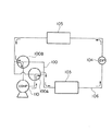
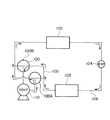
本発明の関連技術として、空調装置などの配管に設けた三方弁または四方弁が知られている(下記の特許文献1参照)。なお、この空調装置における冷凍サイクルの配管内は冷媒としてCO2などの作動流体を流す。このCO2を用いた冷凍サイクルにおいては、一般に、使用圧力領域が従来の冷媒に比較して10倍以上の圧力で使用されている。この使用圧力が高圧であるために、切替弁において種々の問題点が惹起する。図4は、この空調機の冷凍サイクルを示すものである。また、図5は、空調機の暖房サイクルを示すものである。更に、図6は、この図5および図6のサイクルに用いられる三方弁の全断面図である。As a related technique of the present invention, a three-way valve or a four-way valve provided in piping such as an air conditioner is known (see Patent Document 1 below). Note that a working fluid such as CO 2 flows as a refrigerant in the piping of the refrigeration cycle in the air conditioner. In this refrigeration cycle using CO 2 , the working pressure region is generally used at a
図4および図5において、100は、第1三方弁100Aと第2三方弁100Bからなる弁装置である。この弁装置100は、コンプレッサ110からの配管に連通している。また、弁装置100の一方の配管は、室外熱交換器103に連通している。更に、弁装置100の他方の配管は、室内熱交換器105に連通している。更にまた、室外熱交換器103と室内熱交換器105とを連通する配管106の途中には膨張弁104が設けられている。そして、図4の冷房サイクルにおいて、作動流体は、時計の回る方向とは反対方向へ流れる。また、図5の暖房サイクルにおいては、作動流体が時計が回る方向と同一方向へ流れる。従って、弁装置100を切り替えることにより、空調装置のサイクルを冷房サイクル(図4)と暖房サイクル(図5)に構成できる。
4 and 5,
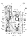
次に、図6により、この冷房と暖房とのサイクルに用いられる一つの三方弁100Aについて説明する。三方弁100Aは、弁本体200と電磁弁250から構成されている。弁本体200は、第1弁部201と第2弁部211と第3弁部221と第4弁部231から構成されている。
Next, one three-
第1弁部201は、球部を設けた第1弁体202が第1弁体孔203に移動自在に嵌合している。この第1弁体202の背面側には第1作用空間206が形成されている。また、第1作用空間206内には第1ばね205が配置されている。この第1ばね205により第1弁体202を図示下方へ弾発に押圧している。そして、第1弁体202は、作動中に第1弁座204と離接する。
In the
第2弁部211は、第1弁部201と対称に配置されている。そして、第2弁体212が第2弁体孔213に移動自在に嵌合している。この第2弁体212は第2作用空間216内に配置された第2ばね215により弾発に押圧されている。そして、第2弁体212は、作動中に第2弁座214と離接する。
The
次に、第3弁部221は、第2弁部211と並列に配置されている。第3弁体222は第3弁体孔223に移動自在に配置されている。この第3弁体222の背面側は第3作用空間226に形成されている。また、第3弁体222は第3作用空間226内に配置された第3ばね225により弾発に押圧されている。そして、第3弁体222は、第3弁座224と離接する。
Next, the
第4弁部231は、可動吸引子251の先端に第4弁体232が設けられている。また、可動吸引子251の背面側は第4空間部に形成されているとともに、この第4空間部に第4ばね255が配置されて可動吸引子251を弾発に押圧している。この第4弁体232の周囲は、第4弁体孔233に形成されている。そして、第4弁体232は、第4弁座234と離接する。第4弁体232は可動吸引子251と一体に作動する。この可動吸引子251は、コイル部に流れる電流に応じて固定吸引子252に吸引される。そして、第4弁体232を第4弁座234の弁口を開閉する。
The
この弁本体200には、図示は省略されているが、第1弁体孔203に連通する第1流体入孔が図6の断面と直交する方向へ設けられている。また、図示は省略されているが、第2流体入孔も図6の断面と直交する方向へ設けられている。さらに、第1弁座204の周りの弁口と第2弁座214の周りの弁口とは第1弁間連通路260により連通している。この第1弁間連通路260と直交する方向には、流体出孔261が形成されている。さらに、弁間連通路260と並列に第3弁座224の弁口と第4弁座234の弁口とを連通する第2弁間連通路263が形成されている。なお、第2弁間連通路263内には、ピン227が設けられており、このピン227の各端部が第3弁体222と第4弁体232にそれぞれ接合している。さらに、第1弁間連通路260と第2弁間連通路263とは戻り流路262により連通している。さらにまた、第1作用空間206内と第4弁体孔233内とは第1パイロット流路264により連通している。また、第2作用空間216内と第3弁体孔223内とは第2パイロット流路265により連通している。
Although not shown, the
このように構成された三方弁100Aは、電磁弁250のコイルに電流が流れると可動吸引子251が固定吸引子252に吸引されるので、第4弁座234の弁口が開弁し、第1作動空間206と第1パイロット流路264と戻り流路262と第1弁間連通路260が連通する。このために、第1作動空間206の圧力が低下すると、第1弁体202が第1弁座204から離脱して開弁する。このとき、前述の第1流体入口から流入した冷媒は流体出孔261へ流出する。反対に、第4弁体232が第4弁座234に閉弁しているときは、第1弁体202が閉弁状態になるので、冷媒は流体出孔261への流出が防止される。また、電磁弁250のコイルへの電流が遮断されると、可動吸引子251が固定吸引子252から図示下方へ離脱するので、可動吸引子251に押されたピン227が第3弁体222を押圧して第3弁座224から開弁させる。このとき、第2流体入口から流入した冷媒は、流体出孔261へ流出する。反対に、第3弁体222が第3弁座224に閉弁しているときは、第2弁体212が閉弁状態になるので、冷媒は流体出孔261への流出が防止される。
In the three-
この三方弁100Aは、電磁弁250に流れる電流により、第3弁部221と第4弁部231との弁口を交互に開閉して第1作用空間206内と第2作用空間216内との圧力を加減し、第1流体入孔と第2流体入孔から流入する作動流体の圧力により第1弁体202と第2弁体212を開閉弁する。このため、三方弁100Aの設定速度に対して実際の開閉速度が遅くなる問題がある。また、第1弁部201と第2弁部211の他に第3弁部221と第4弁部231を設けなければならないので、部品点数が多くなり、三方弁100Aの部品コストが上昇する。この第3弁部221と第4弁部231を電磁弁250により作動させたときの作動流体により、第1弁部201と第2弁部211を作動させるため、第1パイロット流路264および第2パイロット流路265、戻り流路262等の細い流路を設けなければならないので、この細い流路の加工が困難になる。このため、三方弁の製作コストが上昇する問題がある。
This three-
本発明は、上述のような問題点に鑑み成されたものであって、その発明が解決しようとする課題は、作動させる力に応答する弁体の開閉能力を向上させることにある。また、作動流体の流体通路の流量径を大径にも、小径にも製作することが可能にする。さらに、切替弁の弁体の作動構造を簡単にして開閉弁を確実にするとともに、部品点数を少なくし、且つ、製造コストを低減することにある。 The present invention has been made in view of the above-mentioned problems, and a problem to be solved by the invention is to improve the opening / closing ability of a valve body that responds to a force to be actuated. In addition, the flow diameter of the fluid passage of the working fluid can be made large or small. Furthermore, the operation structure of the valve body of the switching valve is simplified to ensure the on-off valve, to reduce the number of parts, and to reduce the manufacturing cost.
本発明は、上述のような技術的課題を解決するために成されたものであって、その技術的解決手段は以下のように構成されている。 The present invention has been made to solve the technical problems as described above, and the technical solution means is configured as follows.
本発明に係わる切替弁は、流入流体通路と流出流体通路とに連通する弁室を切り替える切替弁であって、第1弁座と第1弁座と対向する第2弁座とを有する弁室と、弁室の第1弁座の周りの第1弁口に連通して第1作動流体を流入させる第1流体通路と、弁室に連通して第1作動流体を流入させ、または第2作動流体を流出させる第2流体通路と、弁室の第2弁座の周りの第2弁口に連通して第3作動流体を流出させる第3流体通路と、弁室に配置されて第1弁座と第2弁座とに交互に離接する弁体と、弁体と連結する軸部と、軸部の移動を案内する案内孔と、案内孔の周囲に設けられたシール手段の収容室と、収容室と第1流体通路とを連通する補助通路と、軸部に連結するソレノイドロッドを作動させて弁体を作動させるソレノイド部とを具備し、第1弁座と弁体が接合した周りの内面で第1作動流体の圧力を受ける第1受圧面積と、収容室内の第3作動流体の圧力を受ける軸部の第3受圧面積とをほぼ同一面積にしたものである。 A switching valve according to the present invention is a switching valve that switches a valve chamber communicating with an inflow fluid passage and an outflow fluid passage, and has a first valve seat and a second valve seat facing the first valve seat. A first fluid passage that communicates with the first valve port around the first valve seat of the valve chamber and allows the first working fluid to flow in, and communicates with the valve chamber to allow the first working fluid to flow in or second A second fluid passage that allows the working fluid to flow out, a third fluid passage that communicates with the second valve port around the second valve seat of the valve chamber and allows the third working fluid to flow out, and a first that is disposed in the valve chamber. A valve body alternately separating from and coming into contact with the valve seat and the second valve seat, a shaft portion connected to the valve body, a guide hole for guiding the movement of the shaft portion, and a chamber for sealing means provided around the guide hole An auxiliary passage communicating the storage chamber and the first fluid passage, and a solenoid portion for actuating a valve body by actuating a solenoid rod coupled to the shaft portion A first pressure receiving area that receives the pressure of the first working fluid on the inner surface around the first valve seat and the valve body, and a third pressure receiving area of the shaft that receives the pressure of the third working fluid in the storage chamber. Are approximately the same area.
この本発明の切替弁では、第1流体通路から流入した第1作動流体が作用する弁体の第1受圧面積と、補助通路から流入した第1作動流体が作用するシール手段の収容室内の弁軸における第3受圧面積とをほぼ同面積に構成しているから、第1作動流体によって弁体を第1弁座から開弁する力と、収容室内の圧力により弁体を第1弁座に閉弁する力とは対抗してキャンセルする。このため、ソレノイド部に流れる設定された電流の大きさにより弁体を開弁したり、閉弁したりすることが可能になるので、弁体を開閉するときの応答性に優れる。さらに、弁体が作動流体から受ける力に影響されることなく開閉することができるので、第1流体通路の流体通路断面積と第2流通路の流体通路断面積とを任意の断面積の大きさに設計することが可能になる。このため、類似形状の切替弁で作動流体の流量の大きい大型の切替弁に構成することも可能であり、作動流体の流量の少ない小型の切替弁に構成することも可能になる。また、第1流体通路から第2流体通路へ第1作動流体を流すことができる。さらに、第2流体通路から第3流体通路へ第3作動流体を流すことが可能になる。さらにまた、弁体を弁室の中間に保持すれば第1流体通路から第3流体通路へと第1作動流体を流すことも可能である。このために、小型の切替弁で多数の流通路に構成できる。 In the switching valve of the present invention, the first pressure receiving area of the valve body on which the first working fluid flowing in from the first fluid passage acts, and the valve in the accommodating chamber of the sealing means on which the first working fluid flowing in from the auxiliary passage acts. Since the third pressure receiving area in the shaft is substantially the same area, the valve body is moved to the first valve seat by the force of opening the valve body from the first valve seat by the first working fluid and the pressure in the storage chamber. It cancels against the force to close the valve. For this reason, the valve body can be opened and closed depending on the magnitude of the set current flowing through the solenoid portion, and therefore the responsiveness when opening and closing the valve body is excellent. Furthermore, since the valve body can be opened and closed without being affected by the force received from the working fluid, the fluid passage cross-sectional area of the first fluid passage and the fluid passage cross-sectional area of the second flow passage can be arbitrarily increased. It becomes possible to design. For this reason, it is possible to configure a large-sized switching valve with a large flow rate of the working fluid with a similar-shaped switching valve, and it is also possible to configure a small switching valve with a small flow rate of the working fluid. Further, the first working fluid can flow from the first fluid passage to the second fluid passage. Further, the third working fluid can flow from the second fluid passage to the third fluid passage. Furthermore, if the valve body is held in the middle of the valve chamber, the first working fluid can flow from the first fluid passage to the third fluid passage. For this reason, it can comprise in many flow paths with a small switching valve.
1 切替弁
2 弁部
2A バルブハウジング(弁本体)
3 第1弁座
4 第2弁座
5 軸受部
5A 案内孔
5B 穴周面
5C 接触面
6 第1流体通路
6A 第1連通路
7 第2流体通路
7A 第2連通路
8 第3流体通路
8A 第3連通路
10 弁体
10A 第1弁面
10B 第2弁面
11 軸部
11A 外周面
14 弁室
15 補助通路
16 導入路
17 収容室
20 ソレノイド部
21 本体
22 コイル部
23 スリーブ
23A 内周面
24 可動吸引子
24A 外周面
25 固定吸引子
25A 案内面
26 ソレノイドロッド
26A 外周摺動面
30 シールリング(シール手段)
30A 内周面
30B 側面
42 第1ばね(第1ばね手段)
41 補助ばね(第2ばね手段)
P1 第1作動流体
P2 第2作動流体
P2A 第3作動流体
P3 第4作動流体1 Switching valve
2 Valve
2A Valve housing (valve body)
3 1st valve seat
4 Second valve seat
5 Bearing part
5A guide hole
5B hole circumference
5C contact surface
6 First fluid passage
6A 1st passage
7 Second fluid passage
7A Second communication path
8 Third fluid passage
8A 3rd passage
10 Disc
10A 1st valve face
10B 2nd valve face
11 Shaft
11A outer peripheral surface
14 Valve chamber
15 Auxiliary passage
16 Introduction route
17 containment room
20 Solenoid part
21 Body
22 Coil part
23 sleeve
23A Inner peripheral surface
24 Movable suction element
24A outer peripheral surface
25 Fixed suction
25A Information surface
26 Solenoid rod
26A outer peripheral sliding surface
30 Seal ring (sealing means)
30A inner surface
30B side
42 1st spring (1st spring means)
41 Auxiliary spring (second spring means)
P1 First working fluid
P2 Second working fluid
P2A 3rd working fluid
P3 4th working fluid
以下、本発明に係わる実施の形態としての切替弁を図面に基づいて詳述する。尚、以下に説明する各図面は、設計図を基にした正確な図面である。 Hereinafter, a switching valve as an embodiment according to the present invention will be described in detail with reference to the drawings. Each drawing described below is an accurate drawing based on the design drawing.
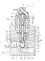
図1は、本発明に係わる第1実施例を示す切替弁1の断面図である。また、図2はシール手段30を示す収容室17の領域の部分断面図である。この切替弁は、例えば、図4に示す冷凍サイクル又は図5に示すような暖房サイクルなどを流れる作動流体の切替に適している。図1および図2に於いて、切替弁1には、外形を形成するバルブハウジング(弁本体とも言う)2Aを設ける。このバルブハウジング2Aは、軸心に弁室14を形成する。この弁室14を中心にして外部から弁室14に第1作動流体P1を流入させる第1流体通路6を設ける。第1流体通路6と弁室14との間は第1連通路6Aに形成する。第1流体通路6と周方向へ約180度廻った位置には、弁室14と連通する第2流体通路7を設ける。この弁室14の第1作動流体P1は、第2流体通路7へ第2作動流体P2(第1作動流体P1と同じ作動流体である)として流出する。また、第2流体通路7から第3作動流体P2A(第2作動流体P2が流入先で作動した後の作動流体である)として弁室14へ流入する。さらに、第2流体通路7の位置から周方向へ約145度廻った位置に弁室14と連通する第3流体通路8を設ける。なお、弁室14と第3流体通路8の間は第3連通路8Aに形成する。そして、第3作動流体P2Aは、第2流体通路7から弁室14に流入するとともに、弁室14から第3連通路8Aを経て第4作動流体P3として第3流体通路8へ流出する。この各第1流体通路6と第2流体通路7と第3流体通路8のバルブハウジング2Aにおける位置関係は、上述のように角度を限定するものではなく、円周上で配管しやすいような位置に間隔を置いて配置すればよい。
FIG. 1 is a sectional view of a switching valve 1 showing a first embodiment according to the present invention. FIG. 2 is a partial cross-sectional view of the region of the
さらに、バルブハウジング2Aにおける弁室14の図示する上部の貫通孔には軸受部5を設ける。この軸受部5の軸心には、案内孔5Aを形成する。この案内孔5Aは後述する軸部11を移動自在に案内する。この案内孔5Aは、ゴムまたは樹脂材製のスリーブ状の薄い軸受を軸受部5の内周面に嵌着して、軸受部5に軸受けを複合材として形成することもできる。この軸受は、軸部11を案内するとともに、シール手段を兼ねることができる。つまり、図示省略した上述の軸受は、第1作動流体をシールするとともに、軸部11も案内する。さらに、バルブハウジング2Aの軸受部5の図示上端部には、二段の取付穴を設ける。この取付穴にはソレノイド部20の図示する下部を嵌着する。また、軸受部5の図示の上面には、周面に沿って複数の溝状の切欠部を形成する。さらに、切欠部を設けた軸受部5の外周はバルブハウジング2Aとソレノイド部20との結合面間に空間部を形成する。この空間部と切欠部とを導入路16に形成する。この導入路16は補助通路15と通して第1流体通路6と連通させる。つまり、補助通路15は一端が第1流体通路6に連通すると共に、他端が導入路16を介して後述するシールリング(シール手段とも言う)30の収容室17と連通する。この補助通路15は、バルブハウジング2Aに対して軸方向に貫通する孔に形成する。
Furthermore, a bearing
弁室14には、第1流体通路6の軸芯と直交する第1連通路6Aの開口に第1弁口を設ける。第1弁口の周りは第1弁座3である。また、第1弁座3と対向する第3連通路8Aの開口にも第2弁口を設ける。この第2弁口の周りは第2弁座4である。さらに、弁室14には弁体10を配置する。この弁体10には、第1弁座3と離接して第1弁口を開閉する第1弁面10Aを設ける。この第1弁面10Aの第1弁座3と密接する内面は第1受圧面積A1である。また、この弁体10に第2弁座4と離接して第2弁口を開閉する第2弁面10Bを設ける。この第2弁面10Bの第2弁座4と密接する内面は第2受圧面積A1である。そして、弁体10は弁室14の内周面と摺動自在に嵌合して第1弁面10Aが第1弁座3と着座するときは、第2弁面10Bが第2弁座4と開弁する。反対に、第1弁面10Aが第1弁座3と開弁するときは、第2弁面10Bが第2弁座4に着座する。この切替弁1は、3方弁として機能する。つまり、弁体10が上下に移動すると、第1弁口と第2弁口とが交互に弁口を開閉する構成である。
The
また、弁体10の弁室14と摺動する下方部は、段部を成す小径部に形成して第1連通路6Aと第2流体通路7とを連通させる通路として第1作動流体P1を通過させる。また、この小径部の外周に第1ばね42(第1ばね手段とも言う)を同芯に配置する。この第1ばね42は、弁体10を第2弁座4側へ弾発に押圧する。なお、弁体10の内周面と摺動する大径部(図示する弁体10の上部)には、軸方向へ貫通する第2連通路7Aを周方向に沿って複数個に設ける。この第2連通路7Aは、第2弁座4の第2弁口が開いた時に、第3連通路8Aと連通する。また、第3連通路8Aは、第3流体通路8と連通して外部の配管と連通する。さらに、軸受部5は、バルブハウジング2Aとは別部品として、バルブハウジング2Aの貫通孔に嵌着しているので、銅合金、焼結合金、樹脂材料を加工して製作することができる。この軸受部5の外周に環状溝を設けて第3連通路8Aの一部としている。そして、この軸受部5の環状溝内と案内孔5Aとを貫通孔により連通させて全体を第3連通路8Aに形成する。この貫通孔は軸受部5の中心から放射状に環状溝内へ達する複数個の孔により形成する。なお、軸受部5を設けることなく、バルブハウジング2Aに直接加工した案内孔5Aを設けても良い。この軸受部5に設けた案内孔5Aの直径寸法(A3の直径)は、軸受部5の内周に設けた第3連通路8Aの直径(A2の直径)と同径寸法に形成すると良い。そして、バルブハウジング2Aは、真鍮、銅、アルミニウム、鉄等の金属、合成樹脂材等で製作する。
The lower portion of the
この軸受部5における案内孔5Aの図示する上部には、上述したように、シールリング30(シール手段ともいう)が取り付けられる収容室17を設ける。図2は、この収容室17の領域を拡大して示すものである。この収容室17は、軸受部5の上面に案内孔5Aの内径寸法より大径寸法にした穴周面5B内に凹状に形成する(図2参照)。また、シールリング30の収容室17は、図2から明らかなように、穴周面5Bと、穴底の接触面5Cとにより形成する。このシールリング30の収容室17には、ゴム材製で断面がO形のシールリング30を装着する。シールリング30の径方向の一側面30Bは接触面5Cに接合させる。また、シールリング30の内周面30Aは、軸部11の外周面11Aに軽く密接させる。
As described above, the
軸部11はソレノイドロッド26と連結する。この軸部11の弁体10と連結する側の軸は、小径の直径D2に形成されてソレノイドロッド26の直径D3とほぼ同径にする。また、軸部11の断面積A3は、案内孔5Aの断面積とほぼ同一面積にするが、軸部11の直径は案内孔5Aの直径より0.05mm以内の微少な寸法にして摺動できるようにする。その上、シールリング30により導入路16から流入した第1作動流体P1が軸部11の外周面11Aと案内孔5Aとの嵌合間から弁室14へ漏洩するのを防止する。なお、この第1作動流体P1は、ソレノイドロッド26の外周摺動面26Aと固定吸引子25の案内面25Aとの間隙内に流入する。そして、第1作動流体P1が軸部11に作用する。この第1作動流体P1が軸部11の断面積A3に作用して押し下げる力と、第1作動流体P1が弁体10の第1受圧面積A1に作用して上方へ押圧する力とを対抗させて釣り合わせる。なお、軸部11の断面積A3と弁体10の第1弁面10Aと第1弁座3との接合する第1受圧面積A1とは、ほぼ同一面積である。このとき、シールリング30の収容室17の穴周面5Bは、シールリング30が作動流体P1により押圧されて弾性変形してもシールリング30の外周面が接触しない大きさにする。このため、シールリング30の外周面は、第1作動流体P1の圧力により軸方向へ圧縮されて径方向へ平面状に伸ばされても穴周面5Bと圧接合しないから、シールリング30の外周面側が自由に伸びることができるので内周面30Aは軸部11の外周面11Aと強く圧接するのが防止できる。その結果、弁体10が開閉弁して軸部11が図示する上下へ移動するときに、シールリング30との摺動抵抗は小さくなる。
The shaft portion 11 is connected to the
バルブハウジング2Aの図示する上端部に設けた取付穴には、ソレノイド部20の本体21の端部を嵌着する。この本体21には、有底円筒状のスリーブ23を同心に設ける。スリーブ23の外周側には、コイル部22を装着する。さらに、コイル部22の外周は、本体21の内周面に本体21と固定吸引子25とが磁界の回路を形成されるように嵌着する。さらに、スリーブ23の内周面23Aの一端側には、可動吸引子24の外周面24Aを移動自在に嵌合する。また、スリーブ23の内周面23Aの他端部は、固定吸引子25と本体21とを結合した間に固定する。さらに、可動吸引子24には、ソレノイドロッド26の一端部を結合する。さらにまた、ソレノイドロッド26の他端面を軸部11の端面に接面する。また、ソレノイドロッド26の外周摺動面26Aは、固定吸引子25の案内面25Aと移動自在に嵌合する。そして、ソレノイド部20の図示する上部に結線した配線を介して電流がコイル部22に印加されると、電流の強さに応じて可動吸引子24が固定吸引子25に吸引される。また、電流が切れると可動吸引子24は第1ばね42により弾発されて固定吸引子25から離脱する。このようにして、ソレノイド部20に流れる電流の大きさに応じて可動吸引子24は、ソレノイドロッド26と連結する弁体10を移動して第1弁座3と第2弁座4に対して交互に離接し、交互に第1弁口と第2弁口を開閉する。なお、可動吸引子24は、補助ばね41(第2ばね手段とも言う)により弁体10側へ弾発に押圧されている。
The end portion of the
上述のように構成された切替弁1において、ソレノイド部20に流れる電流が無印加時には、弁部10はF1の力により作動して開弁する。このF1は、次の式のような力になる。
In the switching valve 1 configured as described above, when no current flowing through the
F1=P1×A1−P1×A3+K1−K2となる。
従って、A1=A3であるから、F1=K1−K2となる。
ただし、A1は第1受圧面積。
P1は第1流体通路6から導入される第1作動流体の圧力。
A3は軸部11の断面積。
K1は第1ばね42の力。
K2は補助ばね41の力。
また、ソレノイド部20に電流が印加される場合には、弁部10はF2の力により作動して閉弁する。このF2は、次の式のような力になる。
F2=P1×A1−P1×A3+K1−K2+Sとなる。
従って、A1=A3であるから、F2=K1−K2+Sとなる。
ただし、Sはソレノイド部20の吸引力。
このため、弁体10は作動流体の力を受けることなく作動できる。F1 = P1 * A1-P1 * A3 + K1-K2.
Therefore, since A1 = A3, F1 = K1-K2.
However, A1 is the first pressure receiving area.
P1 is the pressure of the first working fluid introduced from the
A3 is a cross-sectional area of the shaft portion 11.
K1 is the force of the
K2 is the force of the
Further, when a current is applied to the
F2 = P1 * A1-P1 * A3 + K1-K2 + S.
Therefore, since A1 = A3, F2 = K1-K2 + S.
However, S is the suction force of the
For this reason, the
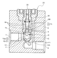
図3は本発明に係わる第2実施例の切替弁1の要部を拡大して示す。図3において、切替弁1の全体構成は、図1とほぼ同一である。図3が図1と相違する点は、弁体10の第2弁面10Bと第2弁座4とが接触する内面の第2受圧面積A2と弁軸の断面積A3と第1受圧面積A1とをほぼ同一面積にしたものである。つまり、弁体10の第1弁面10Aと第1弁座3とが接触した内面の第1受圧面積A1と、弁体10の第2弁面10Bと第2弁座4とが接触する内面の第2受圧面積A2と、弁軸の断面積A3とをほぼ同一面積にしたものである。なお、図3のその他の構成は図1とほぼ同一構成である。
FIG. 3 is an enlarged view of a main part of the switching valve 1 of the second embodiment according to the present invention. In FIG. 3, the whole structure of the switching valve 1 is substantially the same as FIG. 3 differs from FIG. 1 in that the second pressure receiving area A2 of the inner surface where the
上述のように構成された切替弁1において、ソレノイド部20に流れる電流が無印加時には、弁部10はF1の力により作動して開弁する。このF1は、次の式に示す力になる。
F1=P1×A1−P1×A3+K1−K2となる。
従って、A1=A3であるから、F1=K1−K2となる。つまり、この項は、第1実施例と同じである。
ただし、A1は第1受圧面積。
P1は第1流体通路6から導入される第1作動流体の圧力。
A3は軸部11の断面積。
K1は第1ばね42の力。
K2は補助ばね41の力。
次に、ソレノイド部20に電流が印加される場合には、弁部10はF2の力により作動して閉弁する。このF2は、次の式に示す力になる。
F2=P1×A1−P2A×A2+P3×A2+K1−K2+Sとなる。
従って、A1=A2=A3であり、PA2=P3であるから、F1=K1−K2+Sとなる。
ただし、Sはソレノイド部20の吸引力。
このため、弁体10は作動流体の力を受けることなく作動できる。In the switching valve 1 configured as described above, when no current flowing through the
F1 = P1 * A1-P1 * A3 + K1-K2.
Therefore, since A1 = A3, F1 = K1-K2. That is, this term is the same as in the first embodiment.
However, A1 is the first pressure receiving area.
P1 is the pressure of the first working fluid introduced from the
A3 is a cross-sectional area of the shaft portion 11.
K1 is the force of the
K2 is the force of the
Next, when a current is applied to the
F2 = P1 * A1-P2A * A2 + P3 * A2 + K1-K2 + S.
Accordingly, since A1 = A2 = A3 and PA2 = P3, F1 = K1-K2 + S.
However, S is the suction force of the
For this reason, the
上述のように構成された切替弁1は、弁体10と軸部11とを連結するとともに、ソレノイドロッド26と軸部11とを接面して弁体10を作動させる。仮に、この弁体10の開閉時に、弁体10に第1作動流体P1が作用すると、弁体10をソレノイド部20側へ押圧することになる。この弁体10に第1作動流体P1の不釣り合いの作用力が作用するときは、ソレノイド部20に流れる電流の大きさにより作動させる力を不正確にする恐れがある。また、設定された第1ばね42と補助ばね41の力にも影響を与える恐れがある。このため、本発明では第1作動流体P1を弁体10とは反対の軸部11の端面にも作用させて第1作動流体P1が弁体10に作用する力とキャンセルできるようにする。同時に、収容室17とシールリング30との構成により第1作動流体P1が軸部11と案内孔5Aとの嵌合間に漏洩するのを防止するとともに、シールリング30の軸部11との摺動抵抗も低減することができる。その結果、弁体10の開閉は、ソレノイド部20の吸引力、第1ばね42および補助ばね41の各ばね力によって作動することが可能になる。このため、ソレノイド部20および各ばね41,42の作動力により、作動流体の不要な圧力を受けることなく、弁体10の開閉を設定通りに作動させることが期待できる。特に、弁体10の開閉時に作動流体が弁体10に作用して不具合にする不要な圧力や、弁部11を作動させるときの摺動抵抗を小さくできるので、ソレノイド部20の吸引力は、コイル部22に流れる電流の大きさ(強さ)に比例して作動させることができる効果を奏する。
The switching valve 1 configured as described above connects the
以下、本発明に係わる他の実施態様の発明について、その構成と作用効果を説明する。 Hereinafter, the structure and the effect of another embodiment of the present invention will be described.
本発明に係わる第1発明の切替弁は、弁体の第1受圧面積と、軸部の第3受圧面積と、第2弁座と弁体の第2弁面が接合する周りの内面で第3作動流体の圧力を受ける第2受圧面積とをほぼ同一面積にしたものである。 The switching valve according to the first aspect of the present invention has a first pressure receiving area of the valve body, a third pressure receiving area of the shaft portion, and an inner surface around the second valve seat and the second valve surface of the valve body joined together. 3 The second pressure receiving area that receives the pressure of the working fluid is substantially the same area.
この第1発明の切替弁によれば、第1弁座に弁体が接合して第1作動流体の圧力を受ける第1受圧面積と、収容室に内在する弁軸の第3受圧面積と、第2弁座に弁体が接合して第3作動流体の圧力を受ける第2受圧面積とをほぼ同一面積に構成したので、弁軸の第3受圧面積と弁体の第1受圧面積とに作用する作動流体の圧力による軸方向の力は対抗してキャンセルされる。また、第2受圧面積における軸の上下方向に作用する作動流体の力は対抗してキャンセルする。つまり、弁体および軸部に作用する作動流体のすべての力は軸方向で対抗してバランスする。このため、弁体はソレノイド部の作動力または弁体を作動させるばね手段のみの力で作動させることができる。その結果、設定された作動する力により弁体の作動時の開閉の応答能力に優れる。 According to the switching valve of the first aspect of the invention, the first pressure receiving area that receives the pressure of the first working fluid with the valve body joined to the first valve seat, the third pressure receiving area of the valve shaft that is inherent in the storage chamber, Since the second pressure receiving area that receives the pressure of the third working fluid by joining the valve body to the second valve seat is configured to be substantially the same area, the third pressure receiving area of the valve shaft and the first pressure receiving area of the valve body are The axial force due to the pressure of the working fluid acting is canceled in opposition. Further, the force of the working fluid acting in the vertical direction of the shaft in the second pressure receiving area is counteracted and canceled. That is, all the forces of the working fluid acting on the valve body and the shaft portion are counterbalanced in the axial direction. For this reason, the valve body can be operated by the operating force of the solenoid portion or the force of only the spring means for operating the valve body. As a result, the opening / closing response capability during operation of the valve body is excellent due to the set operating force.
本発明に係わる第2発明の切替弁は、ソレノイド部が弁体を第1弁座に閉弁させる吸引力に対抗して弁体を第1弁座から開弁する第1ばね手段と、第1ばね手段に対向する第2ばね手段を有するものである。 A switching valve according to a second aspect of the present invention includes a first spring means for opening the valve body from the first valve seat against a suction force that causes the solenoid portion to close the valve body to the first valve seat; The second spring means is opposed to the first spring means.
この第2発明の切替弁によれば、ソレノイド部による作動力のみで弁体を作動すると、この作動力が小さい範囲では、外力により弁体が振動することがある。しかし、弁体と弁軸において、第1ばね手段と第2ばね手段を対抗させることにより、弁体の振動や揺動が防止できる効果を奏する。このため、乗り物等における空調機や振動する装置に取り付けることを可能にする。 According to the switching valve of the second aspect of the present invention, when the valve body is operated only by the operating force by the solenoid portion, the valve body may vibrate by an external force within a range where the operating force is small. However, when the first spring means and the second spring means are opposed to each other in the valve body and the valve shaft, there is an effect that the vibration and swinging of the valve body can be prevented. For this reason, it can be attached to an air conditioner or a vibrating device in a vehicle or the like.
本発明に係わる第3発明の切替弁は、軸部の弁体に連結する側の外径寸法をソレノイドロッドの外径寸法とほぼ同一寸法にしたものである。 The switching valve according to the third aspect of the present invention is such that the outer diameter dimension of the shaft portion connected to the valve body is substantially the same as the outer diameter dimension of the solenoid rod.
この第3発明の切替弁によれば、弁軸の弁体に連結する外径を弁軸用の案内孔の内径寸法より細い外径寸法にして第3流体通路と弁室との境に第2弁口を形成したものであるから、第2流体通路と第3流体通路とを弁体を介して連通させることが可能になる。そして、軸部と嵌合して案内する案内孔を軸受に適した材料からなる軸受部に設けることも可能になるので、軸受部と軸部とのかじりや摩耗を防止して弁本体を安価な材料で製作することが可能になる。同時に、第3流通路の加工が容易になるとともに、軸部の外周側に形成した連通路により第2流体通路と第3流体通路とを連通することが可能になる。そして、第1弁座と第2弁座とを弁体を介して対向した構成にできる。 According to the switching valve of the third invention, the outer diameter connected to the valve body of the valve shaft is made smaller than the inner diameter size of the guide hole for the valve shaft, and the second fluid passage is separated from the valve chamber by the boundary between the third fluid passage and the valve chamber. Since the two valve ports are formed, the second fluid passage and the third fluid passage can be communicated with each other through the valve body. In addition, since it is possible to provide a guide hole that fits and guides the shaft portion in the bearing portion made of a material suitable for the bearing, the valve body can be inexpensively prevented by preventing galling and wear between the bearing portion and the shaft portion. It becomes possible to manufacture with a simple material. At the same time, the processing of the third flow passage is facilitated, and the second fluid passage and the third fluid passage can be communicated by the communication passage formed on the outer peripheral side of the shaft portion. And it can be set as the structure which opposed the 1st valve seat and the 2nd valve seat via the valve body.
本発明に係わる第4発明の切替弁は、収容室に設けられるシール手段が軸部と圧接しないようにしてシールするものである。 The switching valve according to the fourth aspect of the present invention seals the sealing means provided in the storage chamber so as not to be in pressure contact with the shaft portion.
この第4発明の切替弁では、収容室に設けられるシール手段が作動流体の圧力により弁軸と圧接しないように構成されているので、軸部の移動時の摺動抵抗を小さくして、ソレノイド部に流れる電流が小さいときでも、弁体を電流の強さに応じてスムーズに開閉弁することが可能になる。このため、弁体の開閉の応答性が向上する。 In the switching valve according to the fourth aspect of the present invention, the sealing means provided in the storage chamber is configured not to come into pressure contact with the valve shaft due to the pressure of the working fluid. Even when the current flowing through the portion is small, the valve body can be smoothly opened and closed according to the strength of the current. For this reason, the responsiveness of opening and closing of a valve body improves.
以上のように、本発明の切替弁は、空気機械、圧縮機等の流体回路の切替弁として用いられて開閉弁の応答性の向上と安価な製品として有用である。特に、作動流体の不釣り合いの圧力を受けないようにして作動する弁体に構成し、作動する弁体の応答性に優れた能力を発揮する切替弁として有用である。また、流体通路を任意の大きさに製作可能にして製作コストを低減できる大型、または小型の切替弁として有用である。
As described above, the switching valve of the present invention is used as a switching valve for fluid circuits such as pneumatic machines and compressors, and is useful as an inexpensive product with improved responsiveness of the on-off valve. In particular, it is configured as a valve body that operates so as not to receive an unbalanced pressure of the working fluid, and is useful as a switching valve that exhibits the ability of the operating valve body to be excellent in responsiveness. Further, it is useful as a large-sized or small-sized switching valve that can reduce the manufacturing cost by allowing the fluid passage to be manufactured in an arbitrary size.
Claims (10)
第1弁座と前記第1弁座と対向する第2弁座とを有する弁室と、
前記弁室の前記第1弁座の周りの第1弁口に連通して作用流体を前記弁室に流入させる第1流体通路と、
前記弁室に連通して作用流体を前記弁室から流出させまたは前記弁室に流入させる第2流体通路と、
前記弁室の前記第2弁座の周りの第2弁口に連通して作用流体を前記弁室から流出させる第3流体通路と、
前記弁室に配置されて前記第1弁座と前記第2弁座とに交互に離接する弁体と、
前記弁体と連結する軸部と、
前記軸部の移動を案内する案内孔が形成される軸受部と、
前記軸受部の上面の前記案内孔の周囲に設けられ、穴周面と穴底面により形成される凹状の収容室と、
側面が前記収容室の前記穴底面に接触し、内周面が前記軸部の外周面に接触し、外周面が前記収容室の前記穴周面には接触しないようになっており、前記弁室と前記収容室との間をシールするシール手段と、
前記収容室と前記第1流体通路とを連通する補助通路と、
前記軸部に連結してソレノイドロッドを作動させるソレノイド部と、を具備し、
前記第1弁座と前記弁体が接合した周りの内面で前記第1流体通路からの作動流体の圧力を受ける第1受圧面積と、
前記収容室内の前記第1流体通路からの作動流体の圧力を受ける前記軸部の第3受圧面積とをほぼ同一面積にした切替弁。A switching valve for switching a valve chamber communicating with an inflow fluid passage and an outflow fluid passage,
A valve chamber having a first valve seat and a second valve seat facing the first valve seat;
A first fluid passage communicating with a first valve port around the first valve seat of the valve chamber to allow working fluid to flow into the valve chamber;
A second fluid passage communicating with the valve chamber to allow working fluid to flow out of the valve chamber or into the valve chamber;
A third fluid passage communicating with a second valve port around the second valve seat of the valve chamber to allow working fluid to flow out of the valve chamber;
A valve body disposed in the valve chamber and alternately separating from and contacting the first valve seat and the second valve seat;
A shaft connected to the valve body;
A bearing portion in which a guide hole for guiding the movement of the shaft portion is formed;
Provided around the guide hole of the upper surface of the bearing portion, and a concave-shaped receiving chamber that will be formed by the bore periphery and the hole bottom,
The side surface is in contact with the hole bottom surface of the storage chamber, the inner peripheral surface is in contact with the outer peripheral surface of the shaft portion, and the outer peripheral surface is not in contact with the hole peripheral surface of the storage chamber, Sealing means for sealing between the chamber and the storage chamber;
An auxiliary passage communicating the storage chamber and the first fluid passage;
A solenoid part that is connected to the shaft part and operates a solenoid rod;
A first pressure receiving area that receives the pressure of the working fluid from the first fluid passage on the inner surface around the first valve seat and the valve body joined;
A switching valve having substantially the same area as a third pressure receiving area of the shaft portion that receives the pressure of the working fluid from the first fluid passage in the storage chamber.
Priority Applications (1)
| Application Number | Priority Date | Filing Date | Title |
|---|---|---|---|
| JP2007514673A JP4981663B2 (en) | 2005-04-27 | 2006-04-21 | Switching valve |
Applications Claiming Priority (4)
| Application Number | Priority Date | Filing Date | Title |
|---|---|---|---|
| JP2005130202 | 2005-04-27 | ||
| JP2005130202 | 2005-04-27 | ||
| PCT/JP2006/308419 WO2006118052A1 (en) | 2005-04-27 | 2006-04-21 | Selector valve |
| JP2007514673A JP4981663B2 (en) | 2005-04-27 | 2006-04-21 | Switching valve |
Publications (2)
| Publication Number | Publication Date |
|---|---|
| JPWO2006118052A1 JPWO2006118052A1 (en) | 2008-12-18 |
| JP4981663B2 true JP4981663B2 (en) | 2012-07-25 |
Family
ID=37307852
Family Applications (1)
| Application Number | Title | Priority Date | Filing Date |
|---|---|---|---|
| JP2007514673A Expired - Lifetime JP4981663B2 (en) | 2005-04-27 | 2006-04-21 | Switching valve |
Country Status (6)
| Country | Link |
|---|---|
| US (1) | US7987871B2 (en) |
| EP (1) | EP1876380B1 (en) |
| JP (1) | JP4981663B2 (en) |
| KR (1) | KR101266120B1 (en) |
| CN (1) | CN101166926B (en) |
| WO (1) | WO2006118052A1 (en) |
Families Citing this family (32)
| Publication number | Priority date | Publication date | Assignee | Title |
|---|---|---|---|---|
| JP5233852B2 (en) * | 2009-06-11 | 2013-07-10 | アイシン・エィ・ダブリュ株式会社 | Solenoid valve device |
| US8316888B2 (en) | 2009-06-17 | 2012-11-27 | Eaton Corporation | Fluid-biased hydraulic control valve |
| US8443839B2 (en) | 2009-10-20 | 2013-05-21 | Eaton Corporation | Fluid-biased hydraulic control valve with armature piston |
| JP2011089732A (en) * | 2009-10-26 | 2011-05-06 | Fuji Koki Corp | Heat pump device |
| CN102844599B (en) * | 2010-02-18 | 2015-06-17 | Nt咨询国际有限公司 | Solenoid spool valve |
| JP5726426B2 (en) * | 2010-03-17 | 2015-06-03 | 株式会社不二工機 | Three-way electric valve and heat pump device equipped with the valve |
| CN102803640A (en) * | 2010-04-01 | 2012-11-28 | 多玛两合有限公司 | Hydraulic Solenoid Control Valve |
| KR101572574B1 (en) * | 2010-08-12 | 2015-12-01 | 한온시스템 주식회사 | Expansion valve and air conditioner for vehicle having the same |
| JP5572809B2 (en) * | 2010-09-30 | 2014-08-20 | 株式会社テージーケー | Control valve |
| CN102619998A (en) * | 2011-01-26 | 2012-08-01 | 浙江三花汽车零部件股份有限公司 | Thermal expansion valve |
| DE102011015976A1 (en) * | 2011-04-04 | 2012-10-04 | Bieri Hydraulik Ag | Valve |
| WO2013105411A1 (en) * | 2012-01-12 | 2013-07-18 | イーグル工業株式会社 | Solenoid valve |
| CN102878734B (en) * | 2012-10-26 | 2014-10-15 | 温岭市恒发空调部件有限公司 | Expansion valve |
| JP6240104B2 (en) * | 2015-02-06 | 2017-11-29 | トヨタ自動車株式会社 | Hydraulic brake system |
| US11318923B2 (en) * | 2016-03-30 | 2022-05-03 | Autoliv Nissin Brake Systems Japan Co., Ltd. | Solenoid valve, vehicle brake hydraulic pressure control apparatus and solenoid valve fabrication method |
| JP6626789B2 (en) * | 2016-06-28 | 2019-12-25 | 株式会社不二工機 | Control valve for variable displacement compressor |
| JP2018066291A (en) * | 2016-10-18 | 2018-04-26 | サンデン・オートモーティブコンポーネント株式会社 | Control valve of variable capacity compressor |
| KR102363894B1 (en) * | 2017-09-22 | 2022-02-17 | 엘지전자 주식회사 | Outdoor unit and Air conditioner having the same |
| US10663079B2 (en) | 2017-10-20 | 2020-05-26 | Goodrich Corporation | Electro-pneumatic valve with pressurized container |
| DE102018208893A1 (en) * | 2018-06-06 | 2019-12-12 | Robert Bosch Gmbh | Direct controlled hydraulic directional valve |
| JP2019219006A (en) * | 2018-06-20 | 2019-12-26 | アズビルTaco株式会社 | Electromagnetic valve |
| JP6951706B2 (en) * | 2018-07-17 | 2021-10-20 | 株式会社不二工機 | Flow path switching valve and its assembly method |
| JP7153170B2 (en) * | 2018-08-27 | 2022-10-14 | サンデン株式会社 | COMPOSITE VALVE AND VEHICLE AIR CONDITIONER USING THE SAME |
| US11796067B2 (en) * | 2018-12-05 | 2023-10-24 | Fujikoki Corporation | Valve device |
| EP3951175B1 (en) * | 2019-04-03 | 2026-05-06 | Eagle Industry Co., Ltd. | Capacity control valve |
| CN110925457A (en) * | 2019-12-26 | 2020-03-27 | 鞍山电磁阀有限责任公司 | External pilot solenoid valve |
| EP3879152A1 (en) | 2020-03-11 | 2021-09-15 | Danfoss A/S | Actuator of a refrigerant valve, valve arrangement comprising a refrigerant valve and an actuator and method for mounting an actuator of a refrigerant valve to the refrigerant valve |
| JP7311789B2 (en) * | 2020-03-13 | 2023-07-20 | 浜名湖電装株式会社 | solenoid valve |
| CN115427717A (en) | 2020-04-22 | 2022-12-02 | 伊格尔工业股份有限公司 | Capacity control valve |
| JP7523249B2 (en) * | 2020-04-27 | 2024-07-26 | 川崎重工業株式会社 | Valve mechanism |
| US11293564B2 (en) * | 2020-06-05 | 2022-04-05 | Automatic Switch Company | Valve silencing choke |
| EP4264148A1 (en) * | 2020-12-17 | 2023-10-25 | Bereva S.r.l. | Thermodynamic cycle reversing group for refrigeration circuits with reversible thermodynamic cycle and refrigeration circuit with reversible thermodynamic cycle comprising such reversing group |
Citations (6)
| Publication number | Priority date | Publication date | Assignee | Title |
|---|---|---|---|---|
| JPS4910371B1 (en) * | 1969-07-05 | 1974-03-09 | ||
| JPH01158282A (en) * | 1987-09-10 | 1989-06-21 | Diesel Kiki Co Ltd | Both seat solenoid valve |
| JPH08247361A (en) * | 1995-02-17 | 1996-09-27 | Deublin Co | Seal mechanism of fluid coupling device |
| JPH10196797A (en) * | 1997-01-16 | 1998-07-31 | Smc Corp | Seal structure |
| JPH10332020A (en) * | 1997-06-03 | 1998-12-15 | Ckd Corp | Gas control valve |
| JP2003074736A (en) * | 2001-09-04 | 2003-03-12 | Smc Corp | Solenoid valve |
Family Cites Families (12)
| Publication number | Priority date | Publication date | Assignee | Title |
|---|---|---|---|---|
| FR1193775A (en) * | 1959-11-04 | |||
| US2404514A (en) * | 1944-11-18 | 1946-07-23 | Westinghouse Air Brake Co | Valve device |
| CH416252A (en) * | 1963-11-27 | 1966-06-30 | Teves Kg Alfred | Impact valve |
| JPS5223595B2 (en) | 1972-05-31 | 1977-06-25 | ||
| DE2262247A1 (en) * | 1972-12-20 | 1974-06-27 | Teves Gmbh Alfred | ELECTROMAGNETIC VALVE |
| CA1021225A (en) * | 1974-06-28 | 1977-11-22 | General Signal Corporation | Quick-acting valve assembly |
| JPS6312293Y2 (en) * | 1980-10-08 | 1988-04-08 | ||
| JPS6056431B2 (en) | 1980-10-09 | 1985-12-10 | 三菱電機株式会社 | plasma etching equipment |
| US4844122A (en) | 1987-09-10 | 1989-07-04 | Diesel Kiki Co., Ltd. | Electromagnetic valve with two opposed valve seats |
| DE58909504D1 (en) * | 1989-01-28 | 1995-12-21 | Kuhnke Gmbh Kg H | Balanced lift valve. |
| US5718264A (en) * | 1996-06-10 | 1998-02-17 | Sturman Industries | High speed 3-way control valve |
| US5836230A (en) * | 1996-08-27 | 1998-11-17 | Oded E. Sturman | High speed 2-way control valve |
-
2006
- 2006-04-21 US US11/919,080 patent/US7987871B2/en active Active
- 2006-04-21 EP EP20060745550 patent/EP1876380B1/en not_active Expired - Lifetime
- 2006-04-21 CN CN2006800146609A patent/CN101166926B/en not_active Expired - Lifetime
- 2006-04-21 JP JP2007514673A patent/JP4981663B2/en not_active Expired - Lifetime
- 2006-04-21 WO PCT/JP2006/308419 patent/WO2006118052A1/en not_active Ceased
- 2006-04-21 KR KR1020077024870A patent/KR101266120B1/en not_active Expired - Lifetime
Patent Citations (6)
| Publication number | Priority date | Publication date | Assignee | Title |
|---|---|---|---|---|
| JPS4910371B1 (en) * | 1969-07-05 | 1974-03-09 | ||
| JPH01158282A (en) * | 1987-09-10 | 1989-06-21 | Diesel Kiki Co Ltd | Both seat solenoid valve |
| JPH08247361A (en) * | 1995-02-17 | 1996-09-27 | Deublin Co | Seal mechanism of fluid coupling device |
| JPH10196797A (en) * | 1997-01-16 | 1998-07-31 | Smc Corp | Seal structure |
| JPH10332020A (en) * | 1997-06-03 | 1998-12-15 | Ckd Corp | Gas control valve |
| JP2003074736A (en) * | 2001-09-04 | 2003-03-12 | Smc Corp | Solenoid valve |
Also Published As
| Publication number | Publication date |
|---|---|
| CN101166926A (en) | 2008-04-23 |
| US20090038697A1 (en) | 2009-02-12 |
| EP1876380B1 (en) | 2013-01-02 |
| KR101266120B1 (en) | 2013-05-27 |
| CN101166926B (en) | 2010-08-04 |
| WO2006118052A1 (en) | 2006-11-09 |
| EP1876380A4 (en) | 2011-08-17 |
| US7987871B2 (en) | 2011-08-02 |
| EP1876380A1 (en) | 2008-01-09 |
| KR20080015399A (en) | 2008-02-19 |
| JPWO2006118052A1 (en) | 2008-12-18 |
Similar Documents
| Publication | Publication Date | Title |
|---|---|---|
| JP4981663B2 (en) | Switching valve | |
| JP4246975B2 (en) | Capacity control valve | |
| US8413685B2 (en) | Control valve | |
| JP5080612B2 (en) | Flow path switching valve | |
| JP4888912B2 (en) | Seal structure and control valve using the seal structure | |
| EP2910874A1 (en) | Pilot operated electromagnetic valve | |
| JP5341433B2 (en) | 3-way selector valve | |
| JP2023002057A (en) | solenoid valve | |
| JP2004092734A (en) | Four-way switching valve | |
| CN113028120A (en) | Electromagnetic switching valve | |
| CN109990115B (en) | Electromagnetic switching valve | |
| JP7321521B2 (en) | on-off valve | |
| JP2001208224A (en) | Four-way control valve | |
| JPH0132389B2 (en) | ||
| JP2004144151A (en) | Channel selector valve | |
| CN115451155A (en) | Flow path switching valve | |
| JP2007113617A (en) | Selector valve unit | |
| JP2022186293A (en) | Electric driving valve | |
| JPH02120581A (en) | Four-way valve for refrigerating cycle | |
| JPS63285380A (en) | Four-way valve for refrigerating cycle | |
| JPS63180779A (en) | Four-way valve for refrigerating cycle | |
| JPH02133763A (en) | Four-way valve for freezing cycle | |
| JPS6372974A (en) | Four-way valve | |
| JPS62180184A (en) | Four-way valve for refrigerating cycle | |
| JPH0718491B2 (en) | Four-way valve for refrigeration cycle |
Legal Events
| Date | Code | Title | Description |
|---|---|---|---|
| A621 | Written request for application examination |
Free format text: JAPANESE INTERMEDIATE CODE: A621 Effective date: 20090120 |
|
| A131 | Notification of reasons for refusal |
Free format text: JAPANESE INTERMEDIATE CODE: A131 Effective date: 20110621 |
|
| A521 | Request for written amendment filed |
Free format text: JAPANESE INTERMEDIATE CODE: A523 Effective date: 20110804 |
|
| A521 | Request for written amendment filed |
Free format text: JAPANESE INTERMEDIATE CODE: A523 Effective date: 20110804 |
|
| A521 | Request for written amendment filed |
Free format text: JAPANESE INTERMEDIATE CODE: A523 Effective date: 20110902 |
|
| A072 | Dismissal of procedure [no reply to invitation to correct request for examination] |
Free format text: JAPANESE INTERMEDIATE CODE: A072 Effective date: 20120125 |
|
| A131 | Notification of reasons for refusal |
Free format text: JAPANESE INTERMEDIATE CODE: A131 Effective date: 20120214 |
|
| A521 | Request for written amendment filed |
Free format text: JAPANESE INTERMEDIATE CODE: A523 Effective date: 20120302 |
|
| TRDD | Decision of grant or rejection written | ||
| A01 | Written decision to grant a patent or to grant a registration (utility model) |
Free format text: JAPANESE INTERMEDIATE CODE: A01 Effective date: 20120327 |
|
| A01 | Written decision to grant a patent or to grant a registration (utility model) |
Free format text: JAPANESE INTERMEDIATE CODE: A01 |
|
| A61 | First payment of annual fees (during grant procedure) |
Free format text: JAPANESE INTERMEDIATE CODE: A61 Effective date: 20120420 |
|
| FPAY | Renewal fee payment (event date is renewal date of database) |
Free format text: PAYMENT UNTIL: 20150427 Year of fee payment: 3 |
|
| R150 | Certificate of patent or registration of utility model |
Ref document number: 4981663 Country of ref document: JP Free format text: JAPANESE INTERMEDIATE CODE: R150 Free format text: JAPANESE INTERMEDIATE CODE: R150 |
|
| R250 | Receipt of annual fees |
Free format text: JAPANESE INTERMEDIATE CODE: R250 |
|
| R250 | Receipt of annual fees |
Free format text: JAPANESE INTERMEDIATE CODE: R250 |
|
| R250 | Receipt of annual fees |
Free format text: JAPANESE INTERMEDIATE CODE: R250 |
|
| R250 | Receipt of annual fees |
Free format text: JAPANESE INTERMEDIATE CODE: R250 |
|
| R250 | Receipt of annual fees |
Free format text: JAPANESE INTERMEDIATE CODE: R250 |
|
| R250 | Receipt of annual fees |
Free format text: JAPANESE INTERMEDIATE CODE: R250 |
|
| R250 | Receipt of annual fees |
Free format text: JAPANESE INTERMEDIATE CODE: R250 |
|
| R250 | Receipt of annual fees |
Free format text: JAPANESE INTERMEDIATE CODE: R250 |
|
| R250 | Receipt of annual fees |
Free format text: JAPANESE INTERMEDIATE CODE: R250 |
|
| R250 | Receipt of annual fees |
Free format text: JAPANESE INTERMEDIATE CODE: R250 |
|
| R250 | Receipt of annual fees |
Free format text: JAPANESE INTERMEDIATE CODE: R250 |