EP1124066A1 - Vilebrequin pour moteur à combustion interne - Google Patents
Vilebrequin pour moteur à combustion interne Download PDFInfo
- Publication number
- EP1124066A1 EP1124066A1 EP01400332A EP01400332A EP1124066A1 EP 1124066 A1 EP1124066 A1 EP 1124066A1 EP 01400332 A EP01400332 A EP 01400332A EP 01400332 A EP01400332 A EP 01400332A EP 1124066 A1 EP1124066 A1 EP 1124066A1
- Authority
- EP
- European Patent Office
- Prior art keywords
- piston
- crankshaft
- counterweight
- axis
- peripheral contour
- Prior art date
- Legal status (The legal status is an assumption and is not a legal conclusion. Google has not performed a legal analysis and makes no representation as to the accuracy of the status listed.)
- Withdrawn
Links
- 238000002485 combustion reaction Methods 0.000 title claims abstract description 10
- 230000002093 peripheral effect Effects 0.000 claims abstract description 28
- 238000006073 displacement reaction Methods 0.000 claims description 4
- 238000000034 method Methods 0.000 description 4
- 238000004880 explosion Methods 0.000 description 3
- 239000000463 material Substances 0.000 description 2
- 239000000203 mixture Substances 0.000 description 2
- 230000000694 effects Effects 0.000 description 1
- 239000000446 fuel Substances 0.000 description 1
- 238000004519 manufacturing process Methods 0.000 description 1
- 230000007935 neutral effect Effects 0.000 description 1
- 210000000056 organ Anatomy 0.000 description 1
Images

Classifications
-
- F—MECHANICAL ENGINEERING; LIGHTING; HEATING; WEAPONS; BLASTING
- F16—ENGINEERING ELEMENTS AND UNITS; GENERAL MEASURES FOR PRODUCING AND MAINTAINING EFFECTIVE FUNCTIONING OF MACHINES OR INSTALLATIONS; THERMAL INSULATION IN GENERAL
- F16C—SHAFTS; FLEXIBLE SHAFTS; ELEMENTS OR CRANKSHAFT MECHANISMS; ROTARY BODIES OTHER THAN GEARING ELEMENTS; BEARINGS
- F16C3/00—Shafts; Axles; Cranks; Eccentrics
- F16C3/04—Crankshafts, eccentric-shafts; Cranks, eccentrics
- F16C3/20—Shape of crankshafts or eccentric-shafts having regard to balancing
-
- F—MECHANICAL ENGINEERING; LIGHTING; HEATING; WEAPONS; BLASTING
- F16—ENGINEERING ELEMENTS AND UNITS; GENERAL MEASURES FOR PRODUCING AND MAINTAINING EFFECTIVE FUNCTIONING OF MACHINES OR INSTALLATIONS; THERMAL INSULATION IN GENERAL
- F16C—SHAFTS; FLEXIBLE SHAFTS; ELEMENTS OR CRANKSHAFT MECHANISMS; ROTARY BODIES OTHER THAN GEARING ELEMENTS; BEARINGS
- F16C3/00—Shafts; Axles; Cranks; Eccentrics
- F16C3/04—Crankshafts, eccentric-shafts; Cranks, eccentrics
- F16C3/06—Crankshafts
Definitions
- the invention relates to a crankshaft for an engine with internal combustion
- the invention relates more particularly to a crankshaft for internal combustion engine which rotates around an axis of rotation and which comprises at least one radial flange which brings to its opposite ends a crank pin and an eccentric counterweight of the type whose counterweight is angularly delimited by two stops and radially by a curved peripheral contour convex, and of the type with the underside of the piston and the outline counterweight device are separated by a distance predetermined when the piston is in bottom dead center.
- each connecting rod foot is connected to the corresponding piston and the other end, called the head connecting rod, is rotatably mounted on a cylindrical element of the crankshaft called crankpin.
- crank pins are connected to each other by flanges substantially transverse and their axes of revolution are offset from the axis of rotation of the crankshaft. So, when the axes of the big end, the crankpin and the rotation of the crankshaft are not aligned, the efforts of each connecting rod on the matching crankpin cause a couple that puts in move the crankshaft.
- counterweights are arranged on the crankshaft opposite each crankpin relative to the axis of rotation of the crankshaft. These counterweights thus make it possible to increase the inertia of the crankshaft and dynamically balance it.
- counterweights which are located on the flanges transverse opposite the corresponding crankpin with respect to the axis of rotation of the crankshaft. They are delimited angularly by two edges and radially by a convex curved contour which is generally circular and centered on the axis of rotation of the crankshaft. The radius of the curved contour is limited by the need the existence of a working clearance between the counterweight and the underside of the piston when the latter is in neutral low.
- One of them is to increase the "angle" of the counterweight that is to say the angle which exists between the two edges.
- Another solution proposes to increase the number of counterweight.
- the present invention proposes to optimize the shape of the counterweight to obtain maximum inertia and minimum weight increase.
- the invention proposes a crankshaft of the type described previously characterized in that the distance between the underside of the piston and the peripheral contour remains substantially constant when passing the counterweight opposite screw on the underside of the piston so as to increase the inertia counterweight.
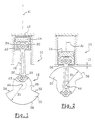
- Figures 1 and 2 show a device 10 which allows to transform the energy produced by the explosion of the mixture fueled in a chamber 12 of a combustion engine in one torque.
- the device 10 notably consists of a piston 14 a connecting rod 16 and a crankshaft 18.
- the piston 14 is mounted in translation in the combustion 12 along a vertical axis A1.
- the connecting rod 16 consists of a foot 20 which is mounted at rotation about a piston axis 24 of axis A2, and of a head 22 which is rotatably mounted around a pin 26 of axis A3 eccentric with respect to an axis A4 of rotation of the crankshaft 18.
- the axes A2, A3 and A4 are parallel to each other.
- crank pin 26 is fixed on a flange 28 of the crankshaft 18.
- a counterweight 30 integral with the flange 28 is eccentric with respect to to the axis A4 of rotation of the crankshaft 18.
- Counterweight 30 is delimited angularly by two stops 32 and 34 of substantially radial orientation, and radially by a convex curved peripheral contour 36 which, in section transverse and as can be seen in the figures, is circular with radius R1 and is centered on the axis of rotation A4 of the crankshaft 18.
- Figure 2 illustrates the imperatives to be taken into account. account for determining the radius R1 of the contour peripheral 36.
- the peripheral contour 36 of the counterweight 30 is opposite the underside 38 of the piston 14. So that the counterweight 30 does not not collide with the underside 38 in its position extreme, a minimum operating clearance J1 must be provided which may be of the order of a few tenths of a mm.
- the radius R1 of peripheral contour 36 then corresponds to the difference between the distance (measured along axis A1) between the axis of rotation A4 of crankshaft 18 and underside 38 of piston 14 at point low death, and the operating clearance J1.
- the invention aims to determine the peripheral contour 36 so that the operating clearance J1 is optimum during the rotation of the crankshaft 18, when the peripheral contour 36 is facing the underside 38 of the piston 14. That is to say that the clearance J1 is minimum and substantially constant when the contour device 36 faces the underside 38 of the piston 14.
- the difference between the values of the displacement of the face lower 38 and the operating clearance J1, constant and minimum, provides the distance from the rotation axis A4 to the outline peripheral 36 for the angle of rotation of the crankshaft 18 corresponding.
- Figures 3 and 4 illustrate a method of determination approximate to the optimum shape of the peripheral contour 36 which is in this case defined by a circle passing through three points P1, P2 and P3.
- FIG. 3 illustrates the determination of the first point P1 of the peripheral contour 36. To do this the crankshaft 18 is put in a first position which corresponds to the alignment of stops it 34 with the axis A1 of translation of the piston 14. The point P1 which belongs to stop 34 is placed at the determined distance from the underside 38 of the piston 14 which corresponds to the clearance J1 operation.
- the central point P2 is determined in a similar manner, according to figure 4, when the bisector of the defined angle by the edges 32 and 34 is aligned with the axis A1.
- the point P3 is determined in a similar way to that of the point P1, when the edge 32 is aligned with the axis A1.
- the shape of the approximate optimum contour 40 corresponds then to the circle which passes through the three points P1, P2, P3 defined previously.
- Figure 5 represents on the one hand the optimum contour approached 40 in strong lines and, on the other hand, the contour 36 according to the state of the dashed line technique.
- the area between the approximate optimum contour 40 and the outline 36 according to the state of the art represents the increase of material obtained by the invention.
- crankshaft 18 The increase in the inertia of the crankshaft 18 is all the more more important than additional material is added away from its axis of rotation A4.
- Another method of approximate shape determination optimum of the peripheral contour 36 consists in determining the central point P2 so that it is located at the distance predetermined J1 of the underside 38 of the piston 14, when the axis of articulation A2 of the connecting rod 16 on the piston 14, the axis of the crankpin A3 and the axis of rotation A4 of the crankshaft 18 are aligned.
- the peripheral contour 40 is then a cylinder whose trace circular in the vertical plane of the counterweight 30 passes through the point P2 and is centered on the axis of the crankpin A3. Contour peripheral 40 is angularly limited by edges 32 and 34.
- crankshaft according to the invention makes it possible to reduce the value of the ratio between the mass of the counterweight and the inertia of the crankshaft, compared to the crankshaft according to the state of the technical.
Landscapes
- Engineering & Computer Science (AREA)
- General Engineering & Computer Science (AREA)
- Ocean & Marine Engineering (AREA)
- Mechanical Engineering (AREA)
- Shafts, Cranks, Connecting Bars, And Related Bearings (AREA)
Abstract
Description
- le contour périphérique est sensiblement cylindrique ;
- le contour périphérique passe par trois points qui sont situés sur l'axe vertical de déplacement du piston dans trois positions angulaires différentes du vilebrequin et qui sont situés à la distance prédéterminée de la face inférieure du piston, l'un central, lorsque le piston est au point mort bas, les deux autres de part et d'autre du point central ;
- les deux points situés de part et d'autre du point central sont situés à la distance prédéterminée de la face inférieure du piston, lorsque l'axe d'articulation de la bielle sur le piston, l'axe du maneton et l'axe de rotation du vilebrequin sont alignés ;
- le contour périphérique est centré sur l'axe du maneton lorsque le piston est au point mort bas.
- la figure 1 représente schématiquement, en coupe transversale, un dispositif constitué d'un vilebrequin selon l'état de la technique auquel sont reliés une bielle et un piston, ce dernier étant au point mort haut ;
- la figure 2 représente un dispositif similaire à celui représenté à la figure 1, le piston étant au point mort bas ;
- la figure 3 représente un dispositif similaire à celui représenté aux figures précédentes dans une position intermédiaire qui permet de déterminer la forme du contour du vilebrequin selon l'invention ;
- la figure 4 représente un dispositif similaire à celui représenté à la figure 3 dans une position extrême basse du piston ;
- la figure 5 représente un dispositif similaire à celui représenté à la figure 2 comportant un vilebrequin réalisé selon l'invention.
Claims (5)
- Vilebrequin (18) pour moteur à combustion interne qui tourne autour d'un axe de rotation (A4) et qui comporte au moins un flasque radial (28) qui porte à ses extrémités opposées un maneton (26) et un contrepoids excentré (30), du type dont le contrepoids (30) est délimité angulairement par deux arrêtes (32, 34) et radialement par un contour périphérique (36) courbe convexe, et du type dont la face inférieure (38) d'un piston (14) et le contour périphérique (36) du contrepoids (30) sont séparés par une distance prédéterminée (J1) lorsque le piston (14) est au point mort bas, caractérisé en ce que la distance qui sépare la face inférieure (38) du piston (14) et le contour périphérique (40) reste sensiblement constante lors du passage du contrepoids (30) en vis à vis de la face inférieure (38) du piston (14) de façon à augmenter l'inertie du contrepoids (30).
- Vilebrequin (18) selon la revendication précédente, caractérisé en ce que le contour périphérique (40) est sensiblement cylindrique.
- Vilebrequin (18) selon l'une des revendications 2 ou 3, caractérisé en ce que le contour périphérique (40) passe par trois points (P1, P2, P3) qui sont situés sur l'axe vertical de déplacement du piston (14) dans trois positions angulaires différentes du vilebrequin (18) et qui sont situés à la distance prédéterminée (J1) de la face inférieure (38) du piston (14), l'un (P2) central, lorsque le piston est au point mort bas, les deux autres (P1, P3) de part et d'autre du point central (P2).
- Vilebrequin (18) selon la revendication précédente, caractérisé en ce que le point central (P2) est situé à la distance prédéterminée (J1) de la face inférieure (38) du piston (14), lorsque l'axe d'articulation (A2) de la bielle (16) sur le piston (14), l'axe du maneton (A3) et l'axe de rotation (A4) du vilebrequin (18) sont alignés, et en ce que le contour périphérique (40) est cylindrique et est centré sur l'axe du maneton (A3).
- Vilebrequin (18) selon l'une quelconque des revendications précédentes, caractérisé en ce que le contour périphérique (40) est centré sur l'axe du maneton (A3) lorsque le piston (14) est au point mort bas.
Applications Claiming Priority (2)
| Application Number | Priority Date | Filing Date | Title |
|---|---|---|---|
| FR0001708 | 2000-02-11 | ||
| FR0001708A FR2805015B1 (fr) | 2000-02-11 | 2000-02-11 | Vilebrequin pour moteur a combustion interne |
Publications (1)
| Publication Number | Publication Date |
|---|---|
| EP1124066A1 true EP1124066A1 (fr) | 2001-08-16 |
Family
ID=8846898
Family Applications (1)
| Application Number | Title | Priority Date | Filing Date |
|---|---|---|---|
| EP01400332A Withdrawn EP1124066A1 (fr) | 2000-02-11 | 2001-02-09 | Vilebrequin pour moteur à combustion interne |
Country Status (2)
| Country | Link |
|---|---|
| EP (1) | EP1124066A1 (fr) |
| FR (1) | FR2805015B1 (fr) |
Cited By (2)
| Publication number | Priority date | Publication date | Assignee | Title |
|---|---|---|---|---|
| WO2008015532A3 (fr) * | 2006-07-31 | 2008-03-27 | Toyota Motor Co Ltd | Masse d'équilibrage |
| DE202021100494U1 (de) * | 2021-02-02 | 2021-02-16 | Liebherr-Components Colmar Sas | Kurbelwelle mit mindestens einem Gegengewicht |
Citations (5)
| Publication number | Priority date | Publication date | Assignee | Title |
|---|---|---|---|---|
| US3978828A (en) * | 1972-08-14 | 1976-09-07 | Caterpillar Tractor Co. | V-Type internal combustion engine |
| DE3443701A1 (de) * | 1984-11-30 | 1986-06-05 | August Dipl.-Kaufm. Dipl.-Braum. 8580 Bayreuth Rothhäusler | Kurbelwelle fuer verbrennungsmotoren mit exzentrischer pleuellagerung |
| DE3741636A1 (de) * | 1986-12-11 | 1988-06-23 | Avl Verbrennungskraft Messtech | Kurbelwelle |
| EP0372724A2 (fr) * | 1988-12-09 | 1990-06-13 | SATURN CORPORATION (a Delaware corp.) | Moteur et vilebrequin correspondant à faible vibration |
| JPH0460236A (ja) * | 1990-06-27 | 1992-02-26 | Mazda Motor Corp | エンジンのクランクシャフト |
-
2000
- 2000-02-11 FR FR0001708A patent/FR2805015B1/fr not_active Expired - Fee Related
-
2001
- 2001-02-09 EP EP01400332A patent/EP1124066A1/fr not_active Withdrawn
Patent Citations (5)
| Publication number | Priority date | Publication date | Assignee | Title |
|---|---|---|---|---|
| US3978828A (en) * | 1972-08-14 | 1976-09-07 | Caterpillar Tractor Co. | V-Type internal combustion engine |
| DE3443701A1 (de) * | 1984-11-30 | 1986-06-05 | August Dipl.-Kaufm. Dipl.-Braum. 8580 Bayreuth Rothhäusler | Kurbelwelle fuer verbrennungsmotoren mit exzentrischer pleuellagerung |
| DE3741636A1 (de) * | 1986-12-11 | 1988-06-23 | Avl Verbrennungskraft Messtech | Kurbelwelle |
| EP0372724A2 (fr) * | 1988-12-09 | 1990-06-13 | SATURN CORPORATION (a Delaware corp.) | Moteur et vilebrequin correspondant à faible vibration |
| JPH0460236A (ja) * | 1990-06-27 | 1992-02-26 | Mazda Motor Corp | エンジンのクランクシャフト |
Non-Patent Citations (1)
| Title |
|---|
| PATENT ABSTRACTS OF JAPAN vol. 016, no. 253 (M - 1263) 9 June 1992 (1992-06-09) * |
Cited By (4)
| Publication number | Priority date | Publication date | Assignee | Title |
|---|---|---|---|---|
| WO2008015532A3 (fr) * | 2006-07-31 | 2008-03-27 | Toyota Motor Co Ltd | Masse d'équilibrage |
| DE202021100494U1 (de) * | 2021-02-02 | 2021-02-16 | Liebherr-Components Colmar Sas | Kurbelwelle mit mindestens einem Gegengewicht |
| EP4036438A1 (fr) | 2021-02-02 | 2022-08-03 | Liebherr-Components Colmar SAS | Vilebrequin pourvu d'au moins un contrepoids |
| US11732775B2 (en) | 2021-02-02 | 2023-08-22 | Liebherr-Components Colmar Sas | Crankshaft having at least one counterweight |
Also Published As
| Publication number | Publication date |
|---|---|
| FR2805015A1 (fr) | 2001-08-17 |
| FR2805015B1 (fr) | 2002-05-03 |
Similar Documents
| Publication | Publication Date | Title |
|---|---|---|
| EP0222841A1 (fr) | Manivelle de vilebrequin | |
| US4481918A (en) | Means for reducing vibration in reciprocating engines | |
| JPS62220710A (ja) | クランク軸 | |
| EP0052387B1 (fr) | Moteur comportant au moins un piston à mouvement de translation linéaire et plateau oscillant destiné à un tel moteur | |
| EP1491725A2 (fr) | Dispositif de guidage d'une aube à angle de calage variable | |
| FR2805015A1 (fr) | Vilebrequin pour moteur a combustion interne | |
| FR2512110A1 (fr) | Dispositif d'equilibrage perfectionne pour moteur a trois cylindres | |
| FR2512108A1 (fr) | Dispositif d'equilibrage perfectionne pour moteur a trois cylindres | |
| EP3094844B1 (fr) | Système de distribution pour moteur bicylindre | |
| FR2496760A1 (fr) | Moteur a frottements reduits | |
| FR2802973A1 (fr) | Moteur a combustion interne a cylindree et taux de compression variables | |
| FR2905729A1 (fr) | Moteur a combustion interne pour vehicule automobile | |
| FR2500530A1 (fr) | Commande desmodromique a fermetures auto-compensees pour les soupapes d'admission et d'echappement des moteurs a combustion interne | |
| FR2501785A1 (fr) | Dispositif d'avance a l'injection, pour moteurs a combustion interne | |
| FR2856111A1 (fr) | Moteur a combustion interne a taux de compression variable | |
| FR2464409A1 (fr) | Dispositif d'equilibrage pour machine a piston | |
| FR2726876A1 (fr) | Moteur a combustion interne a piston alternatif avec compensation des vibrations dues a la torsion | |
| NL8800793A (nl) | Inrichting voor het slijpen van een lagertap van de krukas van een verbrandingsmotor in het bijzonder een dieselmotor. | |
| FR2774727A1 (fr) | Pompe a vide a faible bruit et rendement eleve | |
| FR2627803A1 (fr) | Dispositif d'equilibrage des masses | |
| FR2560931A1 (fr) | Perfectionnement aux soupapes a lame | |
| FR3138670A1 (fr) | Procédé de correction d’une mesure de position angulaire dans un moteur à combustion interne | |
| FR2897896A1 (fr) | Attelage mobile d'un moteur a taux de compression variable a axe de bielle auto-lubrifie | |
| BE332249A (fr) | ||
| EP4242478A1 (fr) | Vilebrequin à réduction des chocs dans l huile |
Legal Events
| Date | Code | Title | Description |
|---|---|---|---|
| PUAI | Public reference made under article 153(3) epc to a published international application that has entered the european phase |
Free format text: ORIGINAL CODE: 0009012 |
|
| AK | Designated contracting states |
Kind code of ref document: A1 Designated state(s): AT BE CH CY DE DK ES FI FR GB GR IE IT LI LU MC NL PT SE TR Kind code of ref document: A1 Designated state(s): AT BE |
|
| AX | Request for extension of the european patent |
Free format text: AL;LT;LV;MK;RO;SI |
|
| AKX | Designation fees paid | ||
| REG | Reference to a national code |
Ref country code: DE Ref legal event code: 8566 |
|
| RAP1 | Party data changed (applicant data changed or rights of an application transferred) |
Owner name: RENAULT S.A.S. |
|
| 17P | Request for examination filed |
Effective date: 20020708 |
|
| RBV | Designated contracting states (corrected) |
Designated state(s): AT BE |
|
| RBV | Designated contracting states (corrected) |
Designated state(s): DE GB |
|
| GRAP | Despatch of communication of intention to grant a patent |
Free format text: ORIGINAL CODE: EPIDOSNIGR1 |
|
| STAA | Information on the status of an ep patent application or granted ep patent |
Free format text: STATUS: THE APPLICATION HAS BEEN WITHDRAWN |
|
| 18W | Application withdrawn |
Effective date: 20050307 |