EP1123180B1 - Device for producing and/or processing mixtures consisting of multiple constituents - Google Patents
Device for producing and/or processing mixtures consisting of multiple constituents Download PDFInfo
- Publication number
- EP1123180B1 EP1123180B1 EP99949009A EP99949009A EP1123180B1 EP 1123180 B1 EP1123180 B1 EP 1123180B1 EP 99949009 A EP99949009 A EP 99949009A EP 99949009 A EP99949009 A EP 99949009A EP 1123180 B1 EP1123180 B1 EP 1123180B1
- Authority
- EP
- European Patent Office
- Prior art keywords
- cam
- stirrer
- housing
- outlet
- shaft
- Prior art date
- Legal status (The legal status is an assumption and is not a legal conclusion. Google has not performed a legal analysis and makes no representation as to the accuracy of the status listed.)
- Expired - Lifetime
Links
Images


Classifications
-
- B—PERFORMING OPERATIONS; TRANSPORTING
- B29—WORKING OF PLASTICS; WORKING OF SUBSTANCES IN A PLASTIC STATE IN GENERAL
- B29B—PREPARATION OR PRETREATMENT OF THE MATERIAL TO BE SHAPED; MAKING GRANULES OR PREFORMS; RECOVERY OF PLASTICS OR OTHER CONSTITUENTS OF WASTE MATERIAL CONTAINING PLASTICS
- B29B7/00—Mixing; Kneading
- B29B7/30—Mixing; Kneading continuous, with mechanical mixing or kneading devices
- B29B7/34—Mixing; Kneading continuous, with mechanical mixing or kneading devices with movable mixing or kneading devices
- B29B7/38—Mixing; Kneading continuous, with mechanical mixing or kneading devices with movable mixing or kneading devices rotary
- B29B7/40—Mixing; Kneading continuous, with mechanical mixing or kneading devices with movable mixing or kneading devices rotary with single shaft
- B29B7/405—Mixing heads
- B29B7/407—Mixing heads with a casing closely surrounding the rotor, e.g. with conical rotor
-
- B—PERFORMING OPERATIONS; TRANSPORTING
- B29—WORKING OF PLASTICS; WORKING OF SUBSTANCES IN A PLASTIC STATE IN GENERAL
- B29B—PREPARATION OR PRETREATMENT OF THE MATERIAL TO BE SHAPED; MAKING GRANULES OR PREFORMS; RECOVERY OF PLASTICS OR OTHER CONSTITUENTS OF WASTE MATERIAL CONTAINING PLASTICS
- B29B7/00—Mixing; Kneading
- B29B7/30—Mixing; Kneading continuous, with mechanical mixing or kneading devices
- B29B7/34—Mixing; Kneading continuous, with mechanical mixing or kneading devices with movable mixing or kneading devices
- B29B7/38—Mixing; Kneading continuous, with mechanical mixing or kneading devices with movable mixing or kneading devices rotary
- B29B7/40—Mixing; Kneading continuous, with mechanical mixing or kneading devices with movable mixing or kneading devices rotary with single shaft
- B29B7/401—Mixing; Kneading continuous, with mechanical mixing or kneading devices with movable mixing or kneading devices rotary with single shaft having a casing closely surrounding the rotor, e.g. with a plunger for feeding the material
-
- B—PERFORMING OPERATIONS; TRANSPORTING
- B29—WORKING OF PLASTICS; WORKING OF SUBSTANCES IN A PLASTIC STATE IN GENERAL
- B29B—PREPARATION OR PRETREATMENT OF THE MATERIAL TO BE SHAPED; MAKING GRANULES OR PREFORMS; RECOVERY OF PLASTICS OR OTHER CONSTITUENTS OF WASTE MATERIAL CONTAINING PLASTICS
- B29B7/00—Mixing; Kneading
- B29B7/30—Mixing; Kneading continuous, with mechanical mixing or kneading devices
- B29B7/58—Component parts, details or accessories; Auxiliary operations
- B29B7/582—Component parts, details or accessories; Auxiliary operations for discharging, e.g. doors
-
- B—PERFORMING OPERATIONS; TRANSPORTING
- B29—WORKING OF PLASTICS; WORKING OF SUBSTANCES IN A PLASTIC STATE IN GENERAL
- B29B—PREPARATION OR PRETREATMENT OF THE MATERIAL TO BE SHAPED; MAKING GRANULES OR PREFORMS; RECOVERY OF PLASTICS OR OTHER CONSTITUENTS OF WASTE MATERIAL CONTAINING PLASTICS
- B29B7/00—Mixing; Kneading
- B29B7/74—Mixing; Kneading using other mixers or combinations of mixers, e.g. of dissimilar mixers ; Plant
- B29B7/76—Mixers with stream-impingement mixing head
- B29B7/7663—Mixers with stream-impingement mixing head the mixing head having an outlet tube with a reciprocating plunger, e.g. with the jets impinging in the tube
- B29B7/7684—Parts; Accessories
-
- B—PERFORMING OPERATIONS; TRANSPORTING
- B29—WORKING OF PLASTICS; WORKING OF SUBSTANCES IN A PLASTIC STATE IN GENERAL
- B29B—PREPARATION OR PRETREATMENT OF THE MATERIAL TO BE SHAPED; MAKING GRANULES OR PREFORMS; RECOVERY OF PLASTICS OR OTHER CONSTITUENTS OF WASTE MATERIAL CONTAINING PLASTICS
- B29B7/00—Mixing; Kneading
- B29B7/74—Mixing; Kneading using other mixers or combinations of mixers, e.g. of dissimilar mixers ; Plant
- B29B7/76—Mixers with stream-impingement mixing head
- B29B7/7631—Parts; Accessories
- B29B7/7652—Construction of the discharge orifice, opening or nozzle
- B29B7/7657—Adjustable discharge orifices, openings or nozzle openings, e.g. for controlling the rate of dispensing
Definitions
- the invention relates to a device for manufacturing and / or for processing multicomponent mixtures, in particular of Plastic mixtures, with a mixing head with at least one Inlet for the mixture or its components, with an im Mixing head rotating drivable stirrer for mixing the mixture or its components and with an outlet for the mixture, wherein the stirrer in the mixing head by means of a drive unit is arranged axially displaceable and according to his Axialposition the outlet releases or closes.
- the volume in the mixing area of the mixing head is increased so much within a very short time, that depending on the rheology of the mixture produced or its Do not component this fast enough from its inlet along the mixer side walls through the mixing area in Direction can flow to the spout, which increased abruptly To fill volumes in this area. It can then do so come that when the sudden lifting of the stirrer in the mixing head a vacuum is created, especially if the outlet is still with residues of the ejected in a previous processing Mixture is filled.
- US Pat. No. 4,883,645 shows a static mixing head without stirrer.
- This mixing head is equipped with a cleaning device with a provided with a thin cleaning flask which cleans the mixing chamber, when the supply is interrupted by the components.
- the cleaning piston can be turned off for cleaning and by one Axial drive, such as a cam drive, pushed back and forth become.
- the object of the invention is to provide a device of the aforementioned Art to improve so that a sudden opening or Closing the outlet opening avoided by the stirrer and thereby the adverse influences on sensitive, processed Materials are prevented.
- This task is with the invention achieved in that the drive unit has a mechanical Cam drive with at least one actuating cam having, with an attacking on the stirrer or its shaft Hubelement cooperates, wherein the at least one actuating cam a cam shape with steady or jerk-free course and one from the closed position to the outlet of the mixing head releasing position of the stirrer towards increasing cam radius Has.
- the cam gear with one or more Actuating cam with variable cam radius for opening the outlet raises the lifting element and thus the stirrer or raise, it is possible to increase the speed of the stirrer when opening from a very low value at the beginning of the lifting movement in the further course of the axial displacement of the stirrer get faster.
- the cam drive allows the Use of actuating cams with various cam surfaces, the optimal to the material and flow behavior of the straight can be adapted to processing material.
- actuating cam a cam shape with steady or have / have smooth progress, they provide for a lifting or Retracting the stirrer in the mixing head with evenly growing Speed without acceleration jumps, that is without sudden movements of the stirrer during the entire opening process, so that the volume in the mixing chamber is continuous enlarged and of the processed material without time delay can be completed. From the closed position to the outlet of the mixing head releasing position of the stirrer out Increasing cam radius makes it possible, while maintaining the same Drive speed of the drive element, the opening speed of the stirrer when opening the outlet continuously to enlarge or at the closing of a high speed at a very low speed just before reaching to reduce the closed position.
- the mixture in the mixing head can already to this, during the opening movement the most critical When the volume in the mixing head is increasing, so that the stirrer by its displacement in the mixing chamber the mixing head generates no negative pressure and the mixed, too Do not outgas processing multicomponent mixture and thereby can experience a loss of quality.
- the cam drive expediently has at least one actuating cam having camshaft in a bearing housing is rotatably mounted laterally next to the agitator shaft.
- a cam drive with two arranged in parallel Camshafts to provide each with an actuating cam, the in a common bearing housing on both sides of the agitator shaft are rotatably mounted.
- the Hubelement preferably on the agitator shaft, so that the entire Drive unit for the displacement of the stirrer in his Axial direction away from the actual mixing head can be. There is therefore no danger that the drive unit with their partly highly accurate manufactured parts in Contact comes with the multi-component mixture to be processed, resulting in errors or inaccuracies when opening and closing could lead to the outlet.
- a particularly advantageous drive for the camshaft results themselves, if they are each provided with a drive gear are that of an axially displaceable driven Rack drive element are rotatable.
- the rack drive element can do this with a double or circumferential Gearing for both drive gears in the two preferably be provided parallel camshafts.
- the drive element essentially from the piston of a hydraulic or pneumatic piston-cylinder unit consists or coupled with this.
- the of the compressed air or the Hydraulic fluid on the piston of the piston-cylinder unit applied pressure is transmitted through the rack or other suitable Transmission element transferred to the cam drive and of this in the non-uniform, the stirrer with ever-increasing Speed from the outlet lifting opening movement implemented.
- the drive element preferably has an axial guide bore on, at least partially receives the helical compression spring.
- the designed as a helical spring return spring can also in addition to or as an alternative to the guide bore around one Guide pin to be wound, which also ensures that the Spring compressed or pulled apart only in their axial direction can be and a lateral deflection of the spring not taking place.
- the actuating cams of the two parallel camshafts preferably mirror images configured to each other and the associated camshafts are driven in opposite directions.
- the actuating cams can be interchangeable arranged on the associated camshaft, which makes it possible, by simply exchanging only the Actuating cams the opening movement and speed of the Stirrer optimally adapted to various mixtures to be processed.
- the lifting element is preferably in the axial direction of the agitator shaft adjustable connected to this.
- the adjustable connection makes it possible to adjust the device so that the or the actuating cam in the closed position of the stirrer with are very little play without direct contact to the lifting element, so that it is ensured that the stirrer with its tip the Outlet completely closes.
- the lifting element can essentially from an operating sleeve surrounding the stirrer shaft coaxially and one with this adjustable screwed bearing mount exist for a thrust bearing of the agitator shaft. The adjustability of the lifting element on the agitator shaft is then by Einoder Unscrew the bearing receiver from or into the actuating sleeve allows.
- the thrust bearing which is on the lifting element Axial movement exerted by the cams on the stirrer shaft transmits and thereby shifts in the housing, it is preferable from a radial deep groove ball bearing, which thus simultaneously the arranged at one end of the agitator shaft radial shaft bearing forms.
- the radial deep groove ball bearing allows so not just the rotation of the shaft about its own axis, but also allows the transmission of axial forces when rotating Shaft for their displacement in the housing.
- the lifting element is expedient of the or the actuating cam against the action of a closing spring in the housing axially displaceable.
- the closing spring ensures a return of the Lifting element and thus at the same time the stirrer for closing the outlet when the actuating cam in its original Be turned back position before opening the outlet had at the mixing head.
- the closing spring pushes over the lifting element the stirrer shaft and thus the stirrer with its tip firmly against the outlet and closes it against the unwanted Outlet of material still in the mixing chamber reliable.
- the stirrer shaft sleeve-like surrounds and is provided with an external thread, with the in a provided on the actuating sleeve internal thread is screwed.
- the bearing mount of the Housing outside opposite the actuating sleeve adjustable, for what they received axially displaceable in a guide sleeve may be, which is rotatably arranged in the housing while the Bearing support relative to the guide sleeve in the circumferential direction is locked.
- this has at least one stop element for the stirrer or the agitator shaft on.
- the stop element limits the opening travel, the shaft or the stirrer to fully open the Outlet has to cover.
- the stop element may be in a housing head be arranged, with which the housing terminates at the end. The arrangement is preferably made such that the housing head is a cylindrical receptacle for the upper or forms the rear end of the agitator shaft, wherein the receptacle is an internal thread has, in which the stop element screwed adjustably is.
- the adjustable arrangement of the stop element in Housing head allows a change and adjustment of the stroke of the stirrer so that the size of the stirrer tip and the outlet defined annular gap is variable and on Materials with different properties are adapted can.
- the agitator shaft does not strike the stop element itself but the attack takes place indirectly via the camp admission.
- the closing spring can also be in the housing head be arranged, with their first end in the axial direction acting on the agitator shaft or its bearing receptacle and arranged with its second end to a housing head Spring stop supported. It is particularly useful when the spring stop is adjustably arranged in the housing head is, for example, as well as the stop element in the housing head provided internal thread is screwed.
- the first End of the closing spring can be connected to the bearing support Applying spring plate act on the stirrer shaft, the Spring force evenly over the entire circumference of the bearing support distributed and so as pure, centric axial force in the Stirrer initiates.
- Such a procedure that is especially advantageous with the cam drive of the device according to the invention can be carried out, but of course by another suitable drive means on the device such as a controlled hydraulic drive can be realized allows a very gentle treatment even more sensitive Materials in the processing in the mixing head, so that qualitatively high-quality components can be produced by the method.
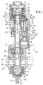
- 10 denotes a device according to the invention for mixing and processing the components of a plastic mixture,
- a sealing foam for example, a sealing foam
- the on Component is molded to form a seal.
- the device 10 consists essentially of a in Figs. 1 and 2 shown below mixing head 11 with an above it flanged bearing housing 12, in turn, at its upper End is completed with a housing head 13.
- a mixing chamber 14 is formed in a manner known per se, into which a plurality of inlets 15 open radially, through which the components of the component to be mixed and not shown be supplied to be sprayed plastic mixture.
- the lower part of the mixing chamber 14 is from the stirrer head 16th a stirrer 17 to form a gap 18 to the wall 19th the mixing chamber filled, with the help of the supplied plastic components can be mixed together.
- the tip 20 immediately before the opening 21 of a mixture outlet, the cannula-like similar to a syringe in the lower or front Tip 23 of the mixing head 11 is arranged.
- the stirrer 17 is connected to a stirrer shaft 24, which is rotatably mounted in the bearing housing 12.
- a stirrer shaft 24 which is rotatably mounted in the bearing housing 12.
- the Drive provides an unillustrated drive motor, to the Housing head 13 is flanged and the output shaft through a disposed in the housing head cover 25 opening in the Housing head protrudes and there via a suitable coupling the upper end of the agitator shaft is connected.
- the stirrer is not only used with its stirring head 16, the individual Components of the plastic mixture to be processed but also has the task of the opening 21 of the outlet 22 with its front tip 20 to close in the manner of a nozzle needle or Ejifug of the mixture.
- the stirrer 17 together with his Stirrer shaft axially displaceable in the mixing chamber 14 and stored the bearing housing 12.
- the arrangement is made in this way, that the agitator shaft 24 relative to the inner ring 26 of the lower main roller bearing 27 of the shaft can move with its outer ring 28 fixed between two housing parts 12a, 12b the bearing housing 12 is installed.
- the agitator shaft 24 with a second bearing 29th stored At her in the drawing upper end is the agitator shaft 24 with a second bearing 29th stored, the inner ring 30 on a shaft paragraph by means of a countered shaft nut 31 is fixed while the outer ring of designed as deep groove ball bearing roller bearing 29th is arranged in a bearing receptacle 32.
- the bearing again is mounted axially displaceable in a guide sleeve 33, being to prevent rotation relative to the guide sleeve has a groove 35 extending in the axial direction 34, in the one arranged on the guide sleeve, radially inwardly projecting Retaining pin 36 engages.
- the guide sleeve 33 with one of the Housing outside 37 accessible tool connection 38 provided so that they use a suitable tool from the outside in the housing can be twisted.
- the cam drive 40 has two parallel camshafts 41 with one each, formed at one end of the camshaft actuating cam 42a, b, in the bearing housing 12 on both sides of the agitator shaft are rotatably mounted transversely to this.
- the camshafts 41 provided with drive gears 43a, b, about them from a common rack drive element 44 with double teeth 45 are rotatable in opposite directions.
- the rack drive member 44 is driven by a piston rod 46 of a piston 47 formed, the part of a pneumatic Piston-cylinder unit 48, which is also in the Housing 12 is located laterally next to the agitator shaft.
- the piston rod 46 is as Hollow cylinder formed with an axial guide bore 51st for a helical compression spring 52, on the one hand at the bottom of the hole 53 of the guide bore 51 arranged on a there Spring pad 54 and on the other hand on the upper end face 55th a cylinder chamber 56 is supported, in which the piston rod 46th is received axially displaceable.
- the helical compression spring 52 serves as a return spring for the piston 47 in the dashed, lowest position, if the cylinder chamber 49 is not acted upon by compressed air.
- actuating cams 42a, b are configured in mirror image to each other and have a cam radius r , which steadily increases over a rotation angle of about 180 ° from a minimum value to a maximum value.
- the cams 42 act on the lower end of an actuating sleeve 59 which surrounds the agitator shaft 24 and forms a lifting element 60 for displacing the agitator shaft 24 together with the mixing head 16 arranged thereon, together with the bearing receptacle 32 screwed in at the upper end of the actuating sleeve.
- the closing spring 64 presses over the spring plate 61, the bearing seat 32 and the upper deep groove ball bearing 29 the agitator shaft 24 and thus also the stirring head 16 firmly after down towards the mixing chamber 14, in which the stirrer tip 20 then tightly against the edge of the opening 21 applies.
- Fig. 4 one recognizes that in the lowest Position of the lifting element 16, ie in the opening 21st closing position of the stirring head 16, between the actuating cam 42a, b and the actuating sleeve 59 a small gap remains.
- This gap serves to ensure that the Stirring head with its tip 20 over the stirrer shaft and the rest involved components of the device of the closing spring 64th actually pressed into tight contact with the edge of the opening 21 is, so sure completely closed and not about an annular gap between the tip 20 and the edge of the opening 21st remains, without the recognizable in Fig. 4 gap 66 between Actuating cam and actuating sleeve could occur.
- the special serves already indicated above Embodiment of the guide sleeve 33, the axially displaceable therein, relative to the guide sleeve, however, non-rotatable bearing support 33 and the actuating sleeve 59, in its passage bore 67 provided for the agitator shaft 24 with a thread 68 is, in which the bearing holder 32 with a threaded extension 69 is screwed.
- the actuating sleeve 59 is in the housing 12th Although recorded axially displaceable, but may be opposite Do not twist the housing, resulting in a non-circular cross-section the actuating sleeve 59 is made possible by a Comparison of the wall thicknesses of the sleeve 59 in Figs. 1 and 2 can be seen is.
- the guide sleeve 33 from one of the housing outside 37 forth on the tool connection 38 connected tool in the housing twisted be, with the retaining pin 36 entrains the bearing seat 32 and depending on the direction of rotation, the threaded extension 69 in the actuating sleeve on or unscrews and so the axial position of the Actuating sleeve changed in the housing.
- the relative position of Lifting element 60 and actuating cam of the cam drive 40 can to be easily and accurately adjusted so that the game 66 between cam and actuating sleeve in the in Fig. 4th shown closure position as low as possible, but in each Case is sufficiently large to secure closure in the mixing head to ensure.
- the invention is not limited to the illustrated and described Embodiment limited, but there are many Changes and additions, without the scope of the invention leave.
- the actuating cam replaceable to attach to the camshaft and not the complete camshafts, but only the cams themselves exchange.
- pneumatic cylinder can of course also a hydraulic cylinder or another suitable drive for the cam gear selected be, for example, an electric motor, which has a suitable Reduction gear, the two camshafts rotates.
- radial ball bearings for the stirrer shaft can also be used for high stirrer speeds particularly suitable needle roller bearing or the like. use find, in which case the axial movement of the lifting element via a separate axial roller bearing is transmitted to the agitator shaft, since Needle roller bearings other than deep groove ball bearings do not allow axial forces transfer assets.
Landscapes
- Engineering & Computer Science (AREA)
- Mechanical Engineering (AREA)
- Processing And Handling Of Plastics And Other Materials For Molding In General (AREA)
- Agricultural Chemicals And Associated Chemicals (AREA)
Abstract
Description
Die Erfindung betrifft eine Vorrichtung zum Herstellen und/oder zum Verarbeiten von Mehrkomponentengemischen, insbesondere von Kunststoffgemischen, mit einem Mischkopf mit mindestens einem Einlaß für das Gemisch oder dessen Komponenten, mit einem im Mischkopf drehend antreibbaren Rührer zum Vermischen des Gemisches bzw. dessen Komponenten und mit einem Auslaß für das Gemisch, wobei der Rührer im Mischkopf mittels einer Antriebseinheit axial verschieblich angeordnet ist und entsprechend seiner Axialposition den Auslaß freigibt oder verschließt.The invention relates to a device for manufacturing and / or for processing multicomponent mixtures, in particular of Plastic mixtures, with a mixing head with at least one Inlet for the mixture or its components, with an im Mixing head rotating drivable stirrer for mixing the mixture or its components and with an outlet for the mixture, wherein the stirrer in the mixing head by means of a drive unit is arranged axially displaceable and according to his Axialposition the outlet releases or closes.
Beim Verarbeiten von Kunststoffgemischen, beispielsweise zum Herstellen einer an einem Ventildeckel unmittelbar angespritzten Dichtung, sollen die einzelnen Komponenten des Kunststoffgemisches möglichst erst unmittelbar vor der Verarbeitung des Mehrkomponentenkunststoffes miteinander gemischt werden. Zur Herstellung und Verarbeitung von Mehrkomponentengemischen ist aus der DE-OS 42 35 850 eine gattungsgemäße Vorrichtung bekannt, bei der die einzelnen Komponenten des zu verarbeitenden Kunststoffgemisches einem Mischkopf zugeführt und in diesem mittels eines rotierenden Rührers miteinander gemischt werden. Das fertig gerührte Gemisch kann den Mischkopf über einen Auslauf verlassen und durch diesen direkt in eine Form gespritzt oder an ein Bauteil, beispielsweise als Dichtung angeformt werden. Bei der bekannten Mischvorrichtung dient der Rührer gleichzeitig auch als Verschlußorgan für den Auslauf und ist hierzu über einen an der Rührerwelle angreifenden Pneumatikzylinder im Mischkopf axial verschieblich, wobei der Rührer in einer ersten, unteren Stellung mit einer etwa konischen Spitze den Auslauf ventilnadelartig verschließt und in einer zweiten, angehobenen Stellung den Auslauf freigibt, so daß der fertiggemischte Kunststoff ausgespritzt werden kann.When processing plastic mixtures, for example for Producing a molded directly on a valve cover Seal, intended to the individual components of the plastic mixture preferably only immediately before the processing of the multicomponent plastic be mixed with each other. For the production and processing of multi-component mixtures is out DE-OS 42 35 850 a generic device known at the individual components of the plastic mixture to be processed fed to a mixing head and in this by means of a rotating stirrer are mixed together. The finished stir Mixture may leave the mixing head via a spout and injected directly into a mold or to a component, For example, be formed as a seal. In the known Mixing device serves the stirrer at the same time as Closure member for the spout and this is about a on the Stirrer shaft attacking pneumatic cylinder in the mixing head axially displaceable, wherein the stirrer in a first, lower position with an approximately conical tip the outlet valve needle-like closes and in a second, raised position the Spout releases so that the finished mixed plastic injected can be.
Diese bekannte Vorrichtung hat sich in der Praxis als überaus erfolgreich erwiesen, denn der Rührer wird seiner Doppelfunktion als Rührelement einerseits und Verschlußorgan andererseits ausgesprochen zuverlässig gerecht, so daß Betriebsstörungen nur selten vorkommen und hohe Qualitäten bei den gespritzten Bauteilen, insbesondere auch bei angespritzten Dichtungen, erreicht werden. Es hat sich jedoch gezeigt, daß die bei Verwendung des unmittelbar auf die Rührerwelle wirkenden Pneumatikzylinders schlagartig einsetzende Öffnungs- bzw. Schließbewegung des Rührers in Axialrichtung bei der Verarbeitung empfindlicher Materialien eine Qualitätseinbuße bei den aus dem Gemisch hergestellten Werkstücken, Dichtungen od.dgl. zur Folge hat. Durch das schlagartig einsetzende und sehr schnelle Anheben des Rührers zum Öffnen des Auslasses wird das Volumen im Mischbereich des Mischkopfes innerhalb sehr kurzer Zeit so stark vergrößert, daß je nach Rheologie des hergestellten Gemisches bzw. dessen Komponenten dieses bzw. diese nicht schnell genug von ihrem Einlaß entlang der Mischerseitenwände durch den Mischbereich in Richtung auf den Auslauf fließen können, um das schlagartig vergrößerte Volumen in diesem Bereich auszufüllen. Es kann dann dazu kommen, daß beim schlagartigen Anheben des Rührers im Mischkopf ein Unterdruck entsteht, insbesondere wenn der Auslaß noch mit Resten des bei einer vorangehenden Verarbeitung ausgespritzten Gemisches ausgefüllt ist. Der - wenn auch nur kurzzeitig - im Mischkopf herrschende Unterdruck kann zu einem Ausgasen des hergestellten und zu verarbeitenden Kunststoffgemisches im Mischkopf führen, wodurch das zu verarbeitende Material eine Qualitätseinbuße erfährt bzw. nicht während des gesamten Verarbeitungsvorgangs gleichbleibende Verarbeitungseigenschaften hat. Es kann dann dazu kommen, daß eine mittels der Vorrichtung an einem Bauteil angespritzte Dichtung zu Beginn des Anspritzvorgangs in einem anderen Maße aufschäumt als im weiteren Verlauf der Dichtung, die dadurch keine gleichbleibende Dicke erhält, so daß eine zuverlässige Abdichtung mit der hergestellten Dichtung nicht gewährleistet werden kann.This known device has proven in practice to be exceedingly proved successful, because the stirrer is doing its double function pronounced as a stirring element on the one hand and closure member on the other Reliable, so that malfunction only rarely occur and high qualities of the sprayed components, especially in molded seals, achieved become. However, it has been found that when using the directly acting on the agitator shaft pneumatic cylinder abrupt opening or closing movement of the stirrer in the axial direction when processing sensitive materials a loss of quality in the produced from the mixture Workpieces, seals or the like. entails. By the abrupt and very rapid lifting of the stirrer To open the outlet, the volume in the mixing area of the mixing head is increased so much within a very short time, that depending on the rheology of the mixture produced or its Do not component this fast enough from its inlet along the mixer side walls through the mixing area in Direction can flow to the spout, which increased abruptly To fill volumes in this area. It can then do so come that when the sudden lifting of the stirrer in the mixing head a vacuum is created, especially if the outlet is still with residues of the ejected in a previous processing Mixture is filled. The - if only for a short time - In the mixing head prevailing negative pressure can lead to outgassing the produced and processed plastic mixture in Mixing head lead, whereby the material to be processed a Quality deterioration experiences or not during the entire processing operation has consistent processing characteristics. It can then happen that one by means of the device a component molded seal at the beginning of Anspritzvorgangs foams to a different extent than later the seal, which thereby does not receive a constant thickness, so that a reliable seal with the seal produced can not be guaranteed.
Aus der JP-A-5 124 071 ist ein Axialtrieb für die Extruderschraube einer Spritzgußmaschine bekannt, bei dem ein drehbar antreibbares Wellenende mit mehreren an seinem Umfang angebrachten Steuernuten versehen ist, in denen drehbar gelagerte Mitnehmer gleiten können. Die Mitnehmer sind an einem axial verschieblichen, aber drehfest angeordneten Flansch angeordnet, in dem die Antriebswelle für die Extruderschraube gelagert ist. Bei Drehung des Wellenendes werden die Mitnehmer von den Steuernuten axial verschoben und verschieben dabei den Flansch und damit die Antriebswelle in Axialrichtung.From JP-A-5 124 071 an axial drive for the extruder screw an injection molding machine known in which a rotatable drivable shaft end with several mounted on its circumference Is provided with control grooves, in which rotatably mounted driver can slide. The drivers are on an axially displaceable, but rotatably arranged flange arranged in the the drive shaft is mounted for the extruder screw. at Rotation of the shaft end become the drivers of the control grooves moved axially and thereby move the flange and thus the Drive shaft in the axial direction.
Aus der US-A-3 921 963 ist eine Spritzgußmaschine bekannt, deren Extruderschnecke in Axialrichtung von einem Hydraulikzylinder angetrieben wird und deren Rotationsgeschwindigkeit an vorbestimmte Axialpositionen in Stufen verändert wird.From US-A-3 921 963 an injection molding machine is known, the Extruder screw in the axial direction of a hydraulic cylinder is driven and their rotational speed at a predetermined Axial positions in steps is changed.
Die US-A 4 883 645 zeigt einen statischen Mischkopf ohne Rührer. Dieser Mischkopf ist mit einer Reinigungseinrichtung mit einem dünnen Reinigungskolben versehen, der die Mischkammer säubert, wenn die Zufuhr von den Komponenten unterbrochen wird. Der Reinigungskolben kann für die Reinigung gedreht und von einem Axialantrieb, beispielsweise einem Nockentrieb, vor- und zurückgeschoben werden. US Pat. No. 4,883,645 shows a static mixing head without stirrer. This mixing head is equipped with a cleaning device with a provided with a thin cleaning flask which cleans the mixing chamber, when the supply is interrupted by the components. The cleaning piston can be turned off for cleaning and by one Axial drive, such as a cam drive, pushed back and forth become.
Aufgabe der Erfindung ist es, eine Vorrichtung der eingangs genannten Art so zu verbessern, daß ein schlagartiges Öffnen bzw. Schließen der Auslaßöffnung durch den Rührer vermieden und dadurch die nachteilhaften Einflüsse auf empfindliche, zu verarbeitende Materialien unterbunden werden. Diese Aufgabe wird mit der Erfindung dadurch gelöst, daß die Antriebseinheit einen mechanischen Nockentrieb mit mindestens einer Betätigungsnocke aufweist, die mit einem am Rührer bzw. dessen Welle angreifenden Hubelement zusammenwirkt, wobei die mindestens eine Betätigungsnocke eine Nockenform mit stetigem bzw. ruckfreiem Verlauf und einem von der Schließstellung zur den Auslaß des Mischkopfes freigebenden Stellung des Rührers hin größer werdenden Nockenradius hat.The object of the invention is to provide a device of the aforementioned Art to improve so that a sudden opening or Closing the outlet opening avoided by the stirrer and thereby the adverse influences on sensitive, processed Materials are prevented. This task is with the invention achieved in that the drive unit has a mechanical Cam drive with at least one actuating cam having, with an attacking on the stirrer or its shaft Hubelement cooperates, wherein the at least one actuating cam a cam shape with steady or jerk-free course and one from the closed position to the outlet of the mixing head releasing position of the stirrer towards increasing cam radius Has.
Durch die Verwendung des Nockengetriebes mit einer oder mehreren Betätigungsnocken mit veränderlichem Nockenradius, die zum Öffnen des Auslasses das Hubelement und damit den Rührer anhebt bzw. anheben, ist es möglich, die Geschwindigkeit des Rührers beim Öffnen von einem sehr geringen Wert zu Beginn der Hubbewegung im weiteren Verlauf der Axialverschiebung des Rührers schneller werden zu lassen. Der Nockentrieb erlaubt dabei die Verwendung von Betätigungsnocken mit verschiedenartigen Nockenflächen, die optimal an das Material- und Fließverhalten des gerade verarbeitenden Werkstoffes angepaßt sein können.By using the cam gear with one or more Actuating cam with variable cam radius for opening the outlet raises the lifting element and thus the stirrer or raise, it is possible to increase the speed of the stirrer when opening from a very low value at the beginning of the lifting movement in the further course of the axial displacement of the stirrer get faster. The cam drive allows the Use of actuating cams with various cam surfaces, the optimal to the material and flow behavior of the straight can be adapted to processing material.
Da die Betätigungsnocke(n) eine Nockenform mit stetigem bzw. ruckfreiem Verlauf hat/haben, sorgen sie für ein Anheben bzw. Zurückziehen des Rührers im Mischkopf mit gleichmäßig anwachsender Geschwindigkeit ohne Beschleunigungssprünge, also ohne schlagartige Bewegungen des Rührers während des gesamten Öffnungsvorganges, so daß sich das Volumen im Mischraum kontinuierlich vergrößert und von dem verarbeiteten Material ohne Zeitverzögerung ausgefüllt werden kann. Der von der Schließstellung zur den Auslaß des Mischkopfes freigebenden Stellung des Rührers hin größer werdende Nockenradius ermöglichst es, bei gleichbleibender Antriebsgeschwindigkeit des Antriebselements die Öffnungsgeschwindigkeit des Rührers beim Öffnen des Auslasses kontinuierlich zu vergrößern bzw. bei dessen Schließen von einer hohen Geschwindigkeit auf eine sehr geringe Geschwindigkeit kurz vor Erreichen der Schließstellung zu verringern.Since the actuating cam (s) a cam shape with steady or have / have smooth progress, they provide for a lifting or Retracting the stirrer in the mixing head with evenly growing Speed without acceleration jumps, that is without sudden movements of the stirrer during the entire opening process, so that the volume in the mixing chamber is continuous enlarged and of the processed material without time delay can be completed. From the closed position to the outlet of the mixing head releasing position of the stirrer out Increasing cam radius makes it possible, while maintaining the same Drive speed of the drive element, the opening speed of the stirrer when opening the outlet continuously to enlarge or at the closing of a high speed at a very low speed just before reaching to reduce the closed position.
Da die Öffnungsgeschwindigkeit des den Auslaß ventilnadelartig verschließenden Rührers zu Beginn der Öffnungsbewegung nur gering ist, kann das im Mischkopf befindliche Gemisch auch bereits zu diesem, während der Öffnungsbewegung am meisten kritischen Zeitpunkt das sich vergrößernde Volumen im Mischkopf ausfüllen, so daß der Rührer durch seine Verschiebung in der Mischkammer des Mischkopfes keinen Unterdruck erzeugt und das gemischte, zu verarbeitende Mehrkomponentengemisch nicht ausgasen und dadurch eine Qualitätseinbuße erfahren kann. Im weiteren Verlauf der Öffnungsbewegung, in dem der Einfluß der Öffnungsgeschwindigkeit auf das im Mischkopf zum Auslaß hin strömende Material deutlich geringer wird und die Gefahr von Qualitätseinbußen durch zu schnelle Öffnung nicht mehr vorliegt, wird die Öffnungsgeschwindigkeit durch entsprechende Ausbildung der Betätigungnocke(n) erheblich vergrößert, so daß die Gesamtzeit, innerhalb derer der Auslaß für das Mehrkomponentengemisch vollständig freigegeben wird, nicht größer sein muß als bei den bekannten Vorrichtungen und so eine Verarbeitung des Gemisches innerhalb kürzester Zeit nach Auslösung der Öffnungsbewegung des Rührers erfolgen kann.Since the opening speed of the outlet valve needle-like closing stirrer at the beginning of the opening movement only slightly is, the mixture in the mixing head can already to this, during the opening movement the most critical When the volume in the mixing head is increasing, so that the stirrer by its displacement in the mixing chamber the mixing head generates no negative pressure and the mixed, too Do not outgas processing multicomponent mixture and thereby can experience a loss of quality. In the further course of the Opening movement in which the influence of the opening speed on the flowing in the mixing head to the outlet material clearly decreases and the risk of quality losses due to fast opening is no longer present, the opening speed by appropriate design of the actuating cam (s) significantly increased, so that the total time within which the Outlet for the multicomponent mixture completely released is, must not be greater than in the known devices and so a processing of the mixture within a very short time can be done after triggering the opening movement of the stirrer.
Der Nockentrieb hat zweckmäßig mindestens eine, eine Betätigungsnocke aufweisende Nockenwelle, die in einem Lagergehäuse seitlich neben der Rührerwelle drehbar gelagert ist. Besonders zweckmäßig ist es, einen Nockentrieb mit zwei parallel angeordneten Nockenwellen mit je einer Betätigungsnocke vorzusehen, die in einem gemeinsamen Lagergehäuse beidseitig der Rührerwelle drehbar gelagert sind. Bei dieser Ausführungsform greift das Hubelement vorzugsweise an der Rührerwelle an, so daß die gesamte Antriebseinheit für die Verschiebung des Rührers in seiner Axialrichtung vom eigentlichen Mischkopf entfernt angeordnet sein kann. Es besteht daher keine Gefahr, daß die Antriebseinheit mit ihren zum Teil hochgenau gefertigten Einzelteilen in Kontakt mit dem zu bearbeitenden Mehrkomponentengemisch kommt, was zu Fehlern oder Ungenauigkeiten beim Öffnen und Schließen des Auslasses führen könnte. Durch die Verwendung von zwei parallelen Nockenwellen, die im Gehäuse vorzugsweise gegenläufig zueinander drehend angetrieben sind, wird sichergestellt, daß die bei Drehung der Nockenwellen durch Abwälzen der Nocken am Hubelement erzeugte Axialbewegung ohne störende Querkräfte genau axial in die Rührerwelle eingeleitet wird, so daß diese beim Verschieben des Rührers nicht verkantet wird. Zweckmäßig haben die Nockenwellen ein gemeinsames Antriebselement, wodurch sichergestellt wird, daß die Nocken beider Nockenwellen immer um genau den gleichen Betrag verdreht werden und gleichmäßig auf das Hubelement einwirken, um den Rührer im Mischkopf anzuheben bzw. beim Schließen wieder abzusenken.The cam drive expediently has at least one actuating cam having camshaft in a bearing housing is rotatably mounted laterally next to the agitator shaft. Especially It is expedient to have a cam drive with two arranged in parallel Camshafts to provide each with an actuating cam, the in a common bearing housing on both sides of the agitator shaft are rotatably mounted. In this embodiment, the Hubelement preferably on the agitator shaft, so that the entire Drive unit for the displacement of the stirrer in his Axial direction away from the actual mixing head can be. There is therefore no danger that the drive unit with their partly highly accurate manufactured parts in Contact comes with the multi-component mixture to be processed, resulting in errors or inaccuracies when opening and closing could lead to the outlet. By using two parallel Camshafts, preferably in the housing in opposite directions are driven to rotate each other, it is ensured that the rotation of the camshaft by rolling the cam on Lifting element generated axial movement without disturbing lateral forces exactly is introduced axially into the agitator shaft, so that this at Moving the stirrer is not tilted. Have useful the camshafts create a common drive element, thereby ensuring is that the cams of both camshafts always around exactly the same amount can be twisted and evenly on acting on the lifting element to lift the stirrer in the mixing head or lower when closing.
Eine besonders vorteilhafte Antriebsart für die Nockenwellen ergibt sich, wenn diese mit je einem Antriebszahnrad versehen sind, die von einem in Axialrichtung verschieblich angetriebenen Zahnstangen-Antriebselement drehbar sind. Das Zahnstangen-Antriebselement kann hierbei mit einer Doppel- oder umlaufenden Verzahnung für beide Antriebszahnräder bei den beiden vorzugsweise parallel angeordneten Nockenwellen versehen sein. Durch Verschieben des Zahnstangen-Antriebselements in seiner Axialrichtung werden die beiden Antriebszahnräder der Nockenwellen und damit auch die darauf angeordneten Betätigungsnocken vorzugsweise gegenläufig zueinander verdreht, wobei sich die Nocken mit ihren Nockenflächen am Hubelement abwälzen und dieses je nach Verschieberichtung des Zahnstangen-Antriebselements anheben bzw. zurückziehen oder absenken bzw. vorschieben. Als ganz besonders vorteilhaft hat sich eine Ausgestaltung erwiesen, bei der das Antriebselement im wesentlichen aus dem Kolben einer hydraulischen oder pneumatischen Kolben-Zylindereinheit besteht oder mit diesem gekoppelt ist. Der von der Druckluft bzw. der Hydraulikflüssigkeit auf den Kolben der Kolben-Zylindereinheit ausgeübte Druck wird über die Zahnstange oder ein anderes geeignetes Übertragungselement auf den Nockentrieb übertragen und von diesem in die ungleichförmige, den Rührer mit immer größer werdender Geschwindigkeit von dem Auslaß abhebende Öffnungsbewegung umgesetzt.A particularly advantageous drive for the camshaft results themselves, if they are each provided with a drive gear are that of an axially displaceable driven Rack drive element are rotatable. The rack drive element can do this with a double or circumferential Gearing for both drive gears in the two preferably be provided parallel camshafts. By Moving the rack drive element in its axial direction become the two drive gears of the camshafts and thus also the actuating cam arranged thereon preferably rotated in opposite directions, with the cams roll with their cam surfaces on the lifting element and this ever Lift according to the direction of displacement of the rack drive element or withdraw or lower or advance. As a very special An advantageous embodiment has proved to be advantageous the drive element essentially from the piston of a hydraulic or pneumatic piston-cylinder unit consists or coupled with this. The of the compressed air or the Hydraulic fluid on the piston of the piston-cylinder unit applied pressure is transmitted through the rack or other suitable Transmission element transferred to the cam drive and of this in the non-uniform, the stirrer with ever-increasing Speed from the outlet lifting opening movement implemented.
Bei Verwendung einer Kolbenzylindereinheit für den Antrieb des Nockengetriebes kann ein doppelwirkender Zylinder zur Anwendung kommen, dem Druckluft oder Hydraulikflüssigkeit sowohl in den Zylinderraum als auch in den Ringraum zuführbar ist, um auch das Zurückdrehen der Nocken zum Schließen des Auslasses mit hoher Sicherheit zu gewährleisten. Eine einfacherere und dennoch höchst zuverlässige Ausgestaltung der Erfindung ergibt sich, wenn dem Antriebselement eine Rückstellfeder zugeordnet ist, die bei der Öffnungsbewegung des Rührers zusammengedrückt wird und zum Schließen das Antriebselement wieder in seine ursprüngliche Lage verfährt, die es bei verschlossenem Auslaß einnimmt. Wenn als Antriebselement die Kolbenstange des Kolbens eines hydraulischen oder pneumatischen Zylinders verwendet wird, stellt die Rückstellfeder das Antriebselement automatisch zurück, wenn der Druck im Zylinder der Kolbenzylindereinheit verringert bzw. aufgehoben wird.When using a piston-cylinder unit for driving the Cam gear can be a double-acting cylinder for use come in the compressed air or hydraulic fluid in both the Cylinder space as well as in the annulus can be fed to the well Turn back the cam to close the outlet with high To ensure safety. A simpler and yet highly reliable embodiment of the invention results, if the drive element is associated with a return spring, the is compressed during the opening movement of the stirrer and to close the drive element back to its original Situation proceeds, which it occupies when the outlet is closed. If as a driving element, the piston rod of the piston of a hydraulic or pneumatic cylinder is used, the Return spring the drive element automatically back when the Pressure in the cylinder of the piston-cylinder unit reduced or canceled becomes.
Um zu verhindern, daß die als Schraubendruckfeder ausgebildete Rückstellfeder bei ihrem Zusammendrücken seitlich ausknickt, weist das Antriebselement vorzugsweise eine axiale Führungsbohrung auf, die die Schraubendruckfeder wenigstens teilweise aufnimmt. Die als Schraubenfeder ausgestaltete Rückstellfeder kann auch zusätzlich oder alternativ zu der Führungsbohrung um einen Führungsdorn gewunden sein, der ebenfalls dafür sorgt, daß die Feder nur in ihrer Axialrichtung zusammengedrückt bzw. auseinandergezogen werden kann und ein seitliches Auslenken der Feder nicht stattfindet.To prevent that designed as a helical compression spring Return spring buckles laterally when compressed the drive element preferably has an axial guide bore on, at least partially receives the helical compression spring. The designed as a helical spring return spring can also in addition to or as an alternative to the guide bore around one Guide pin to be wound, which also ensures that the Spring compressed or pulled apart only in their axial direction can be and a lateral deflection of the spring not taking place.
Wie bereits angedeutet, sind die Betätigungsnocken der beiden parallel angeordneten Nockenwellen vorzugsweise spiegelbildlich zueinander ausgestaltet und die zugehörigen Nockenwellen sind gegenläufig zueinander angetrieben. Die Betätigungsnocken können auswechselbar an den zugehörigen Nockenwellen angeordnet sein, wodurch es möglich ist, durch einfachen Austausch lediglich der Betätigungsnocken die Öffnungsbewegung und Geschwindigkeit des Rührers an verschiedene, zu verarbeitende Gemische optimal anzupassen. Alternativ ist es auch möglich, die vollständigen Nokkenwellen auswechselbar im Gehäuse zu lagern und sie zusammen mit den daran angeordneten Betätigungsnocken und ggf. den Antriebszahnrädern gegen andere Nockenwellen auszutauschen, die bei der Verarbeitung eines anderen Materials Vorteile bieten.As already indicated, the actuating cams of the two parallel camshafts preferably mirror images configured to each other and the associated camshafts are driven in opposite directions. The actuating cams can be interchangeable arranged on the associated camshaft, which makes it possible, by simply exchanging only the Actuating cams the opening movement and speed of the Stirrer optimally adapted to various mixtures to be processed. Alternatively, it is also possible to use the complete camshafts interchangeably store in the housing and put them together with the actuating cam arranged thereon and possibly the drive gears to replace it with other camshafts offer advantages when processing a different material.
Das Hubelement ist vorzugsweise in Axialrichtung der Rührerwelle verstellbar an dieser angeschlossen. Der verstellbare Anschluß ermöglicht es, die Vorrichtung so einzujustieren, daß der bzw. die Betätigungsnocken in der Schließstellung des Rührers mit sehr wenig Spiel ohne unmittelbaren Kontakt zum Hubelement sind, so daß sichergestellt ist, daß der Rührer mit seiner Spitze den Auslaß vollständig verschließt. Das Hubelement kann im wesentlichen aus einer die Rührerwelle koaxial umgebenden Betätigungshülse und einer mit dieser einstellbar verschraubten Lageraufnahme für ein Axiallager der Rührerwelle bestehen. Die Verstellbarkeit des Hubelements an der Rührerwelle wird dann durch Einoder Ausschrauben der Lageraufnahme aus der bzw. in die Betätigungshülse ermöglicht. Das Axiallager, das die auf das Hubelement von den Nocken ausgeübte Axialbewegung auf die Rührerwelle überträgt und diese dadurch im Gehäuse verschiebt, besteht vorzugsweise aus einem Radial-Rillenkugellager, das somit gleichzeitig das an einem Ende der Rührerwelle angeordnete Radialwellenlager bildet. Das Radial-Rillenkugellager ermöglicht also nicht nur die Drehung der Welle um ihre eigene Achse, sondern gestattet auch die Übertragung von Axialkräften bei drehender Welle zu deren Verschiebung im Gehäuse.The lifting element is preferably in the axial direction of the agitator shaft adjustable connected to this. The adjustable connection makes it possible to adjust the device so that the or the actuating cam in the closed position of the stirrer with are very little play without direct contact to the lifting element, so that it is ensured that the stirrer with its tip the Outlet completely closes. The lifting element can essentially from an operating sleeve surrounding the stirrer shaft coaxially and one with this adjustable screwed bearing mount exist for a thrust bearing of the agitator shaft. The adjustability of the lifting element on the agitator shaft is then by Einoder Unscrew the bearing receiver from or into the actuating sleeve allows. The thrust bearing, which is on the lifting element Axial movement exerted by the cams on the stirrer shaft transmits and thereby shifts in the housing, it is preferable from a radial deep groove ball bearing, which thus simultaneously the arranged at one end of the agitator shaft radial shaft bearing forms. The radial deep groove ball bearing allows so not just the rotation of the shaft about its own axis, but also allows the transmission of axial forces when rotating Shaft for their displacement in the housing.
Das Hubelement ist zweckmäßig von dem bzw. den Betätigungsnocken entgegen der Wirkung einer Schließfeder im Gehäuse axial verschieblich. Die Schließfeder sorgt für eine Rückstellung des Hubelements und damit gleichzeitig des Rührers zum Verschließen des Auslasses, wenn die Betätigungsnocken in ihre ursprüngliche Stellung zurückverdreht werden, die sie vor Öffnen des Auslasses am Mischkopf inne hatten. Die Schließfeder drückt über das Hubelement die Rührerwelle und damit den Rührer mit seiner Spitze fest gegen den Auslaß und verschließt diesen gegen den ungewollten Austritt von in der Mischkammer noch befindlichen Materials zuverlässig. The lifting element is expedient of the or the actuating cam against the action of a closing spring in the housing axially displaceable. The closing spring ensures a return of the Lifting element and thus at the same time the stirrer for closing the outlet when the actuating cam in its original Be turned back position before opening the outlet had at the mixing head. The closing spring pushes over the lifting element the stirrer shaft and thus the stirrer with its tip firmly against the outlet and closes it against the unwanted Outlet of material still in the mixing chamber reliable.
Eine besonders einfache und elegante Ausgestaltung des Hubelementes ergibt sich, wenn die Lageraufnahme die Rührerwelle hülsenartig umgibt und mit einem Außengewinde versehen ist, mit dem sie in ein an der Betätigungshülse vorgesehenes Innengewinde eingeschraubt ist. Vorzugsweise ist die Lageraufnahme von der Gehäuseaußenseite gegenüber der Betätigungshülse einstellbar, wozu sie in einer Führungshülse axial verschieblich aufgenommen sein kann, die im Gehäuse verdrehbar angeordnet ist, während die Lageraufnahme gegenüber der Führungshülse in Umfangsrichtung arretiert ist. Durch Verdrehen der Führungshülse im Gehäuse wird bei dieser Ausgestaltung auch die Lageraufnahme mit verdreht und kann so in die gewünschte Position in der Betätigungshülse ein- bzw. ausgeschraubt werden. Zur Arretierung der Lageraufnahme gegenüber der Führungshülse ist diese zweckmäßig mit mindestens einem radial nach innen vorspringenden Haltestift versehen, der in eine an der Lageraufnahme in Axialrichtung verlaufenden Nut einfaßt. Die Lageraufnahme kann sich so in Axialrichtung gegenüber der Führungshülse frei verschieben, sich jedoch in Umfangsrichtung gegenüber der Führungshülse nicht verdrehen. Um ein Verdrehen der Führungshülse von der Gehäuseaußenseite in besonders einfacher Weise zu ermöglichen, ist sie zweckmäßig mit einem von der Gehäuseaußenseite zugänglichen Werkzeuganschluß versehen.A particularly simple and elegant design of the lifting element results when the bearing receptacle, the stirrer shaft sleeve-like surrounds and is provided with an external thread, with the in a provided on the actuating sleeve internal thread is screwed. Preferably, the bearing mount of the Housing outside opposite the actuating sleeve adjustable, for what they received axially displaceable in a guide sleeve may be, which is rotatably arranged in the housing while the Bearing support relative to the guide sleeve in the circumferential direction is locked. By turning the guide sleeve in the housing is in this embodiment, the bearing support with twisted and can thus be moved to the desired position in the actuating sleeve or be unscrewed. To lock the bearing support relative to the guide sleeve this is expedient with at least a radially inwardly projecting retaining pin provided, the in a recess extending in the axial direction of the bearing receptacle borders. The bearing seat can be so opposite in the axial direction the guide sleeve move freely, but in the circumferential direction do not twist with respect to the guide sleeve. To one Turning the guide sleeve from the outside of the case in particular easy to enable, it is convenient with an accessible from the outside of the housing tool connection Mistake.
In bevorzugter Ausgestaltung der erfindungsgemäßen Vorrichtung. weist diese mindestens ein Anschlagelement für den Rührer bzw. die Rührerwelle auf. Das Anschlagelement begrenzt den Öffnungsweg, den die Welle bzw. der Rührer zum vollständigen Öffnen des Auslasses zurücklegen muß. Das Anschlagelement kann in einem Gehäusekopf angeordnet sein, mit dem das Gehäuse endseitig abschließt. Dabei ist die Anordnung vorzugsweise so getroffen, daß der Gehäusekopf eine zylindrische Aufnahme für das obere bzw. hintere Ende der Rührerwelle bildet, wobei die Aufnahme ein Innengewinde hat, in das das Anschlagelement verstellbar eingeschraubt ist. Die verstellbare Anordnung des Anschlagelements im Gehäusekopf gestattet eine Veränderung und Anpassung des Hubweges des Rührers, so daß auch die Größe des von der Rührerspitze und dem Auslaß definierten Ringspalts veränderlich ist und an Materialien mit verschiedenen Eigenschaften angepaßt werden kann. Vorzugsweise schlägt die Rührerwelle nicht selbst am Anschlagelement an, sondern der Anschlag erfolgt mittelbar über die Lageraufnahme. Die Schließfeder kann ebenfalls im Gehäusekopf angeordnet sein, wobei sie mit ihrem ersten Ende in Axialrichtung auf die Rührerwelle bzw. deren Lageraufnahme einwirkt und sich mit ihrem zweiten Ende an einem im Gehäusekopf angeordneten Federanschlag abstützt. Dabei ist es besonders zweckmäßig, wenn der Federanschlag verstellbar im Gehäusekopf angeordnet ist, beispielsweise ebenso wie das Anschlagelement in das im Gehäusekopf vorgesehene Innengewinde eingeschraubt ist. Das erste Ende der Schließfeder kann über einen sich an die Lageraufnahme anlegenden Federteller auf die Rührerwelle einwirken, der die Federkraft gleichmäßig über den ganzen Umfang der Lageraufnahme verteilt und so als reine, zentrisch wirkende Axialkraft in den Rührer einleitet.In a preferred embodiment of the device according to the invention. this has at least one stop element for the stirrer or the agitator shaft on. The stop element limits the opening travel, the shaft or the stirrer to fully open the Outlet has to cover. The stop element may be in a housing head be arranged, with which the housing terminates at the end. The arrangement is preferably made such that the housing head is a cylindrical receptacle for the upper or forms the rear end of the agitator shaft, wherein the receptacle is an internal thread has, in which the stop element screwed adjustably is. The adjustable arrangement of the stop element in Housing head allows a change and adjustment of the stroke of the stirrer so that the size of the stirrer tip and the outlet defined annular gap is variable and on Materials with different properties are adapted can. Preferably, the agitator shaft does not strike the stop element itself but the attack takes place indirectly via the camp admission. The closing spring can also be in the housing head be arranged, with their first end in the axial direction acting on the agitator shaft or its bearing receptacle and arranged with its second end to a housing head Spring stop supported. It is particularly useful when the spring stop is adjustably arranged in the housing head is, for example, as well as the stop element in the housing head provided internal thread is screwed. The first End of the closing spring can be connected to the bearing support Applying spring plate act on the stirrer shaft, the Spring force evenly over the entire circumference of the bearing support distributed and so as pure, centric axial force in the Stirrer initiates.
Mit der Erfindung wird ein Verfahren zum Öffnen und Schließen eines Verschlußelements in einer Vorrichtung zum Herstellen und/oder Verarbeiten von Mehrkomponentengemischen vorgeschlagen, zum Betrieb einer Vorrichtung nach dem Oberbegriff des Anspruches 1, bei dem das Verschlußelement bzw. der dieses bildende Rührer beim Öffnen zum Freigeben eines Auslasses erst langsam von der Auslaßöffnung abgehoben und mit zunehmendem Abstand von der Auslaßöffnung zunehmend schneller von dieser weg bewegt wird und bei dem beim Schließen zum Absperren des Auslasses das im Abstand von der Auslaßöffnung befindliche Verschlußelement erst mit höherer Geschwindigkeit auf die Öffnung zu bewegt wird und mit abnehmendem Abstand von der Öffnung bei Annäherung an diese die Schließgeschwindigkeit verringert wird. Ein derartiges Verfahren, daß sich besonders vorteilhaft mit dem Nockentrieb der erfindungsgemäßen Vorrichtung durchführen läßt, aber natürlich auch durch ein anderes geeignetes Antriebsmittel an der Vorrichtung wie zum Beispiel einen gesteuerten Hydraulikantrieb verwirklicht werden kann, ermöglicht eine sehr schonende Behandlung auch empfindlicher Materialien bei der Verarbeitung im Mischkopf, so daß qualitativ hochwertige Bauteile mit dem Verfahren erzeugt werden können. With the invention, a method for opening and closing a closure element in a device for manufacturing and / or processing multicomponent mixtures, for operating a device according to the preamble of claim 1, wherein the closure element or this forming stirrer when opening to release an outlet first slowly lifted from the outlet and with increasing Distance from the outlet increasingly faster away from this is moved and when closing to shut off the Outlet located at a distance from the outlet opening Closure element only at a higher speed on the Opening to be moved and with decreasing distance from the Opening when approaching this the closing speed is reduced. Such a procedure that is especially advantageous with the cam drive of the device according to the invention can be carried out, but of course by another suitable drive means on the device such as a controlled hydraulic drive can be realized allows a very gentle treatment even more sensitive Materials in the processing in the mixing head, so that qualitatively high-quality components can be produced by the method.
Weitere Merkmale und Vorteile der Erfindung ergeben sich aus der nachfolgenden Beschreibung und der Zeichnung, worin eine bevorzugte Ausführungsform der Erfindung an einem Beispiel näher erläutert wird. Es zeigt:
- Fig. 1
- eine Vorrichtung zum Verarbeiten von Kunststoffgemischen nach der Erfindung in einem Vertikalschnitt;
- Fig. 2
- den Gegenstand der Fig. 1 in einem Schnitt längs der Linie II-II;
- Fig. 3
- den Gegenstand der Fig. 1 in einem Querschnitt längs der Linie III-III; und
- Fig. 4
- einen Teil einer Antriebseinheit der erfindungsgemäßen Vorrichtung in deren Schließstellung in einer vergrößerten Schnittdarstellung entsprechend der Darstellung nach Fig. 2.
- Fig. 1
- a device for processing plastic mixtures according to the invention in a vertical section;
- Fig. 2
- the object of Figure 1 in a section along the line II-II.
- Fig. 3
- the object of Figure 1 in a cross section along the line III-III. and
- Fig. 4
- a part of a drive unit of the device according to the invention in its closed position in an enlarged sectional view corresponding to the illustration of FIG. 2nd
In der Zeichnung bezeichnet 10 eine erfindungsgemäße Vorrichtung zum Vermischen und Verarbeiten der Komponenten eines Kunststoffgemisches, beispielsweise eines Dichtungsschaums, der an ein Bauteil zur Bildung einer Dichtung angespritzt wird.In the drawing, 10 denotes a device according to the invention for mixing and processing the components of a plastic mixture, For example, a sealing foam, the on Component is molded to form a seal.
Die Vorrichtung 10 besteht im wesentlichen aus einem in den Fig.
1 und 2 unten dargestellten Mischkopf 11 mit einem daran oben
angeflanschten Lagergehäuse 12, das wiederum an seinem oberen
Ende mit einem Gehäusekopf 13 abgeschlossen ist. Im Mischkopf 11
ist in an sich bekannter Weise eine Mischkammer 14 ausgebildet,
in die mehrere Einlässe 15 radial einmünden, durch die die Komponenten
des zu mischenden und an dem nicht dargestellten Bauteil
anzuspritzenden Kunststoffgemisches zugeführt werden.The
Der untere Teil der Mischkammer 14 wird von dem Rührerkopf 16
eines Rührers 17 unter Bildung eines Spalts 18 zur Wandung 19
der Mischkammer ausgefüllt, mit dessen Hilfe die zugeführten Kunststoffkomponenten
miteinander vermischt werden können. An seinem
vorderen, in der Zeichnung unteren Ende ist der Rührer nach
Art eines Kegels ausgebildet, dessen Spitze 20 unmittelbar vor
der Öffnung 21 eines Gemisch-Auslasses liegt, der kanülenartig
ähnlich wie bei einer Spritze in der unteren bzw. vorderen
Spitze 23 des Mischkopfes 11 angeordnet ist.The lower part of the mixing
Zum Drehantrieb ist der Rührer 17 an eine Rührerwelle 24 angeschlossen,
die im Lagergehäuse 12 drehbar gelagert ist. Für den
Antrieb sorgt ein nicht dargestellter Antriebsmotor, der an den
Gehäusekopf 13 angeflanscht ist und dessen Abtriebswelle durch
eine im Gehäusekopfdeckel 25 angeordnete Öffnung in den
Gehäusekopf hineinragt und dort über eine geeignete Kupplung an
das obere Ende der Rührerwelle angeschlossen ist.For the rotary drive, the
Der Rührer dient mit seinem Rührkopf 16 nicht nur dazu, die einzelnen
Komponenten des zu verarbeitenden Kunststoffgemisches
miteinander zu vermengen, sondern hat darüber hinaus die Aufgabe,
die Öffnung 21 des Auslasses 22 mit seiner vorderen Spitze
20 nach Art einer Düsennadel zu verschließen bzw. zum Ejizieren
des Gemisches freizugeben. Hierzu ist der Rührer 17 mitsamt seiner
Rührerwelle axial verschieblich in der Mischkammer 14 bzw.
dem Lagergehäuse 12 gelagert. Die Anordnung ist dabei so getroffen,
daß sich die Rührerwelle 24 gegenüber dem Innenring 26 des
unteren Hauptwälzlagers 27 der Welle verschieben kann, das mit
seinem Außenring 28 fest zwischen zwei Gehäuseteilen 12a, 12b
des Lagergehäuses 12 eingebaut ist. An ihrem in der Zeichnung
oberen Ende ist die Rührerwelle 24 mit einem zweiten Lager 29
gelagert, dessen Innenring 30 auf einem Wellenabsatz mittels einer
gekonterten Wellenmutter 31 festgelegt ist, während der Außenring
des als Rillenkugellagers ausgestalteten Wälzlagers 29
in einer Lageraufnahme 32 angeordnet ist. Die Lageraufnahme wiederum
ist axial verschieblich in einer Führungshülse 33 gelagert,
wobei sie zur Verdrehsicherung gegenüber der Führungshülse
eine in Axialrichtung 34 verlaufende Nut 35 aufweist, in die ein
an der Führungshülse angeordneter, radial nach innen vorspringender
Haltestift 36 eingreift. The stirrer is not only used with its stirring
An ihrem Außenumfang ist die Führungshülse 33 mit einem von der
Gehäuseaußenseite 37 zugänglichen Werkzeuganschluß 38 versehen,
so daß sie mit einem geeigneten Werkzeug von außen im Gehäuse
verdreht werden kann.At its outer periphery, the
Zum Verschieben der Rührerwelle 24 im Gehäuse 12 und damit zum
Abheben des Rührers 17 von der Öffnung 21 des Auslasses 22 ist
die Vorrichtung mit einer Antriebseinheit 39 versehen, die im
wesentlichen aus einem mechanischen Nockentrieb besteht, der am
besten in den Fig. 2 bis 4 erkennbar ist. Der Nockentrieb 40
weist zwei parallel zueinander angeordnete Nockenwellen 41 mit
je einer, an einem Ende der Nockenwellen ausgebildeten Betätigungsnocke
42a,b auf, die im Lagergehäuse 12 beidseits der Rührerwelle
quer zu dieser drehbar gelagert sind. An ihren anderen
Enden sind die Nockenwellen 41 mit Antriebszahnrädern 43a,b versehen,
über die sie von einem gemeinsamen Zahnstangen-Antriebselement
44 mit Doppelverzahnung 45 gegenläufig drehbar sind.To move the
Das Zahnstangen-Antriebselement 44 wird von einer Kolbenstange
46 eines Kolbens 47 gebildet, der Bestandteil einer pneumatischen
Kolben-Zylindereinheit 48 ist, die sich ebenfalls in dem
Gehäuse 12 seitlich neben der Rührerwelle befindet.The rack drive member 44 is driven by a piston rod
46 of a piston 47 formed, the part of a pneumatic
Piston-
Wie aus Fig. 1 erkennbar ist, ist der Zylinderraum 49 der Kolbenzylindereinheit
48 unten mit einem Verschlußdeckel 50 dicht
verschlossen, an den sich der Kolben in seiner tiefsten, gestrichelt
dargestellten Stellung anlegt. Die Kolbenstange 46 ist als
Hohlzylinder ausgebildet, mit einer axialen Führungsbohrung 51
für eine Schraubendruckfeder 52, die sich einerseits am Bohrungsgrund
53 der Führungsbohrung 51 auf einer dort angeordneten
Federunterlage 54 und andererseits an der oberen Stirnseite 55
eines Zylinderraums 56 abstützt, in dem die Kolbenstange 46
axial verschieblich aufgenommen ist.As can be seen from Fig. 1, the
Die Schraubendruckfeder 52 dient als Rückstellfeder für den Kolben
47 in die gestrichelt dargestellte, tiefste Stellung, wenn
der Zylinderraum 49 nicht mit Druckluft beaufschlagt ist. Um zu
verhindern, daß die vorgespannte Rückstellfeder 52 bei tiefster
Stellung des Kolbens oberhalb der Kolbenstange seitlich ausknickt,
ist ein von der oberen Stirnseite 55 nach unten vorragender
Führungsdorn 57 vorgesehen, um den sich die Schraubenfeder
52 windet.The helical compression spring 52 serves as a return spring for the piston
47 in the dashed, lowest position, if
the
Wendet man sich nun den Fig. 2 und 4 zu, so erkennt man, daß die
Betätigungsnocken 42a,b spiegelbildlich zueinander ausgestaltet
sind und einen Nockenradius r haben, der über einen Drehwinkel
von ca. 180° von einem Minimalwert zu einem Maximalwert stetig
zunimmt. Die Nocken 42 wirken auf das untere Ende einer Betätigungshülse
59, die die Rührerwelle 24 umgibt und die gemeinsam
mit der am oberen Ende der Betätigungshülse eingeschraubten Lageraufnahme
32 ein Hubelement 60 zum Verschieben der Rührerwelle
24 zusammen mit dem daran angeordneten Rührkopf 16 bildet. Zum
Anheben der Lüften des Rührkopfes 16 in der Mischkammer 14 und
damit zum Freigeben der Öffnung 21 wird der Zylinderraum 49 mit
Druckluft beaufschlagt, wodurch der Kolben 47 bei steigendem
Druck im Zylinderraum aus seiner in Fig. 1 gestrichelt dargestellten
Stellung in die durchgezogen gezeichnete Position verfährt.
Die dabei nach oben verschobene Kolbenstange 46 verdreht
dann mittels der mit den Antriebszahnrädern 43a,b kämmenden
Zahnstange 44 die beiden Nockenwellen 41 gegenläufig zueinander,
so daß die Betätigungsnocken 42a,b aus ihrer in Fig. 4 dargestellten
Position in die Lage gem. Fig. 2 verdreht werden und
dabei das aus Betätigungshülse 59 und Lageraufnahme 32 bestehende
Hubelement 60 im Gehäuse axial nach oben verschieben.
Diese Axialbewegung wird über das obere Rillenkugellager 29 auf
die Rührerwelle 24 übertragen, die somit um den gleichen Betrag
wie das Hubelement 60 zusammen mit dem Rührkopf 16 axial angehoben
wird und die Auslaßöffnung 21 dadurch freigibt.Turning now to Figs. 2 and 4, it can be seen that the
Bei Erreichen des größten, gewünschten Öffnungsquerschnittes für
den Gemischauslaß 22, der in den Fig. 1 und 2 dargestellt ist,
schlägt das Hubelement 60 über ein an der oberen Stirnseite der
Lageraufnahme 32 aufliegendes Bauteil 61 an einem Anschlagelement
62 an, das von oben in ein im Gehäusekopf 13 vorgesehenes
Innengewinde 63 verstellbar eingeschraubt ist. Mit dem Anschlagelement
62 wird der Verstellweg der Rührerwelle und damit auch
des Rührkopfes nach oben begrenzt; durch Verschrauben des Anschlagelementes
im Innengewinde kann die Länge des Verstellweges
verändert werden.Upon reaching the largest, desired opening cross-section for
the
Wenn zum Schließen des Gemischauslasses 22 der Druck in der
Kolben-Zylindereinheit 48 verringert wird, drückt die Schraubendruckfeder
52 den Kolben 47 wieder zurück in seine untere, gestrichelt
dargestellte Lage, wodurch auch die von den Nockenwellen
41 angetriebenen Betätigungsnocken 42 in ihre in Fig. 4
dargestellte Position zurückverdreht werden. Der Rührer 17 wird
dabei von einer im Gehäusekopf angeordneten Schließfeder 64 wieder
in die Schließlage vorgeschoben, in der die Spitze 20 des
Rührkopfs 16 die Öffnung 21 des Gemischauslaßes 22 verschließt.
Hierzu stützt sich die als Schraubendruckfeder ausgestaltete
Schließfeder 64 einerseits an dem einen Federteller bildenden
Bauteil 61 und andererseits an einem Federanschlag 65 ab, der
ähnlich wie das Anschlagelement 62 in das Innengewinde 63 am Gehäusekopf
13 eingeschraubt ist und zur Veränderung der Vorspannung
der Schließfeder 64 im Innengewinde vor- oder zurückgeschraubt
werden kann. Die Schließfeder 64 drückt über den Federteller
61, die Lageraufnahme 32 und das obere Rillenkugellager
29 die Rührerwelle 24 und damit auch den Rührkopf 16 fest nach
unten in Richtung auf die Mischkammer 14, in der sich die Rührerspitze
20 dann dicht an den Rand der Öffnung 21 anlegt.When closing the
Wendet man sich nun Fig. 4 zu, so erkennt man, daß in der tiefsten
Stellung des Hubelements 16, also in der die Öffnung 21
verschließenden Position des Rührkopfes 16, zwischen den Betätigungsnocken
42a,b und der Betätigungshülse 59 ein kleiner Spalt
verbleibt. Dieser Spalt dient dazu, sicherzustellen, daß der
Rührkopf mit seiner Spitze 20 über die Rührerwelle und die übrigen
beteiligten Bauteile der Vorrichtung von der Schließfeder 64
tatsächlich in dichten Kontakt mit dem Rand der Öffnung 21 gedrückt
wird, also sicher vollständig geschlossen wird und nicht
etwa ein Ringspalt zwischen Spitze 20 und Rand der Öffnung 21
verbleibt, der ohne den in Fig. 4 erkennbaren Spalt 66 zwischen
Betätigungsnocken und Betätigungshülse auftreten könnte. Zur
Einstellung des Spaltes 66, der im Betrieb der Vorrichtung möglichst
klein sein sollte und üblicherweise nicht mehr als wenige
Mikrometer beträgt, dient die besondere, oben bereits angedeutet
Ausgestaltung der Führungshülse 33, der darin axial verschieblichen,
gegenüber der Führungshülse jedoch drehfesten Lageraufnahme
33 und der Betätigungshülse 59, die in ihrer Durchlaßbohrung
67 für die Rührerwelle 24 mit einem Gewinde 68 versehen
ist, in das die Lageraufnahme 32 mit einem Gewindefortsatz
69 eingeschraubt ist. Die Betätigungshülse 59 ist im Gehäuse 12
zwar axial verschieblich aufgenommen, kann sich jedoch gegenüber
dem Gehäuse nicht verdrehen, was durch einen unrunden Querschnitt
der Betätigungshülse 59 ermöglicht wird, der durch einen
Vergleich der Wandstärken der Hülse 59 in den Fig. 1 und 2 erkennbar
ist. Zum Einstellen des Spaltes 66 kann die Führungshülse
33 von einem von der Gehäuseaußenseite 37 her an dem Werkzeuganschluß
38 angeschlossenen Werkzeug im Gehäuse verdreht
werden, wobei der Haltestift 36 die Lageraufnahme 32 mitnimmt
und je nach Drehrichtung den Gewindefortsatz 69 in die Betätigungshülse
ein- oder ausschraubt und so die axiale Position der
Betätigungshülse im Gehäuse verändert. Die relative Lage von
Hubelement 60 und Betätigungsnocken des Nockentriebs 40 kann
damit einfach und genau so eingestellt werden, daß das Spiel 66
zwischen Nocken und Betätigungshülse in der in Fig. 4
dargestellten Verschlußstellung möglichst gering, aber in jedem
Fall ausreichend groß ist, um einen sicheren Verschluß im Mischkopf
zu gewährleisten.Turning now to Fig. 4, one recognizes that in the lowest
Position of the lifting
Die Erfindung ist nicht auf das dargestellte und beschriebene Ausführungsbeispiel beschränkt, sondern es ergeben sich viele Änderungen und Ergänzungen, ohne den Rahmen der Erfindung zu verlassen. So sind bei dem beschriebenen Ausführungsbeispiel die Nockenwellen mit ihren Betätigungsnocken und den Antriebszahnrädern einteilig ausgestaltet und können als ganzes ausgetauscht werden, beispielsweise, wenn für die Verarbeitung eines anderen Gemisches andere Verhältnisse bei der Öffnungsgeschwindigkeit und -beschleunigung des Rührkopfes gewünscht werden und daher Nocken mit anderen Nockenformen eingebaut werden sollen. Alternativ ist es selbstverständlich auch möglich, die Betätigungsnocken auswechselbar an den Nockenwellen zu befestigen und nicht die kompletten Nockenwellen, sondern nur die Nocken selbst auszutauschen. Anstelle des dargestellten und beschriebenen Pneumatikzylinders kann selbstverständlich auch ein Hydraulikzylinder oder ein anderer geeigneter Antrieb für das Nockengetriebe gewählt werden, beispielsweise ein Elektromotor, der über ein geeignetes Untersetzungsgetriebe die beiden Nockenwellen dreht. Anstelle der beiden bei dem Ausführungsbeispiel eingebauten Radialkugellager für die Rührerwelle können auch für hohe Rührerdrehzahlen besonders geeignete Nadellager od.dgl. Verwendung finden, wobei dann die Axialbewegung des Hubelements über ein separates Axialwälzlager auf die Rührerwelle übertragen wird, da Nadellager anders als Rillenkugellager Axialkräfte nicht zu übertragen vermögen.The invention is not limited to the illustrated and described Embodiment limited, but there are many Changes and additions, without the scope of the invention leave. Thus, in the described embodiment, the Camshafts with their actuating cams and the drive gears one-piece and can be exchanged as a whole for example, when processing another Mixture other ratios at the opening speed and acceleration of the stirring head are desired and therefore Cams are to be installed with other cam shapes. alternative It is of course also possible, the actuating cam replaceable to attach to the camshaft and not the complete camshafts, but only the cams themselves exchange. Instead of the illustrated and described pneumatic cylinder can of course also a hydraulic cylinder or another suitable drive for the cam gear selected be, for example, an electric motor, which has a suitable Reduction gear, the two camshafts rotates. Instead of the two incorporated in the embodiment radial ball bearings for the stirrer shaft can also be used for high stirrer speeds particularly suitable needle roller bearing or the like. use find, in which case the axial movement of the lifting element via a separate axial roller bearing is transmitted to the agitator shaft, since Needle roller bearings other than deep groove ball bearings do not allow axial forces transfer assets.
Claims (33)
- Apparatus for producing and/or processing of mixtures having several components, in particular of plastic mixtures, with a mixing head with at least an inlet for the mixture or its components, with a stirrer which can be driven rotationally in the mixing head for mixing the mixture or its components and with an outlet for the mixture, whereby the stirrer in the mixing head is arranged in an axially displaceable manner by means of a drive unit and releases or closes the outlet in correspondence with its axial position, characterised in that the drive unit (39) comprises a mechanical cam drive (40) with at least one actuating cam (42) which cooperates with a lifting element (60) which engages the stirrer (17) or its shaft (24), whereby the at least one actuating cam (42) has a cam shape with a steady or jerk-free course and a cam radius ( r) which increases from the closing position to the position of the stirrer (17) which releases the outlet (22) of the mixing head (11).
- Apparatus according to claim 1, characterised in that the cam drive (40) comprises at least one cam shaft (41) comprising an actuating cam (42). Which cam shaft is pivotally mounted in a bearing housing (12) on the side next to the stirrer shaft (24).
- Apparatus according to claim 1 or 2, characterised in that the cam drive (40) comprises two cam shafts (41) arranged in parallel with each other, each having an actuating cam (42a,b), which cam shafts are rotationally mounted in a common bearing housing (12) on both sides of the stirrer shaft (24).
- Apparatus according to one of claims 1 to 3, characterised in that the cam shafts (41) in the housing (12) are driven in an oppositely rotating direction.
- Apparatus according to claim 3 or 4, characterised in that the cam shafts (41) comprise a common drive element (44).
- Apparatus according to one of claims 1 to 5, characterised in that the cam shaft(s) (41) is/are provided with one drive gear (43a,b) each, which can be rotated by means of a gear rack drive element (44) which is displaceably driven in the axial direction (34).
- Apparatus according to claim 6, characterised in that the gear rack drive element (44) is provided with a dual or peripheral gearing (45) for both drive gears (43a,b) at two cam shafts (41) which are arranged in parallel.
- Apparatus according to one of claims 1 to 7, characterised in that the drive element (44) essentially consists of the piston (47) of a hydraulic or pneumatic piston-cylinder unit (48) or is coupled thereto.
- Apparatus according to one of claims 1 to 8, characterised in that the drive element (44) is provided with a reset spring (52).
- Apparatus according to claim 9, characterised in that the drive element (44) comprises an axial guide bore (51 ) for the reset spring (52) which is formed as a compression spring.
- Apparatus according to claim 9 or 10, characterised by a guide mandrel (57) for the reset spring (52) which is formed as a compression spring.
- Apparatus according to one of claims 1 to 11, characterised in that the actuating cams (42a,b) of the two cam shafts (41) (41) belonging thereto are driven arranged in a parallel manner are formed in a mirror image to one another and that the cam shafts in a counter-rotating manner.
- Apparatus according to one of claims 1 to 12, characterised in that the cam(s) (42a,b) is/are arranged exchangeably at the corresponding cam shaft (41 ).
- Apparatus according to one of claims 1 to 13, characterised in that the cam shaft(s) (41) is/are mounted exchangeably in the housing (12).
- Apparatus according to one of claims 1 to 14, characterised in that the lifting element (60) is adjustably connected to the stirrer shaft (24) in the axial direction thereof
- Apparatus according to one of claims 1 to 15, characterised in that the lifting element (60) consists essentially of an actuating sleeve (59) which surrounds the stirrer shaft (24) in a coaxial manner and a bearing reception (32) for an axial bearing (29) of the stirrer shaft (24) which can be adjustably threaded thereto.
- Apparatus according to claim 16, characterised in that the axial bearing (29) consists of a radial grooved ball bearing.
- Apparatus according to one of claims 1 to 17, characterised in that the lifting element (60) can be axially displaced by the actuating cam(s) (42a,b) against the action of a closing spring (64) in the housing.
- Apparatus according to one of claims 1 to 18, characterised in that the bearing reception (32) surrounds the stirrer shaft (24) in a sleeve-like manner and is provided with an outer thread (69) with which it is threaded onto an inner thread (68) which is provided at the actuating sleeve (59).
- Apparatus according to one of claims 1 to 19, characterised in that the bearing reception (32) can be adjusted with regard to the actuating sleeve (59) from the outside (37) of the housing.
- Apparatus according to one of claims 1 to 20, characterised in that the bearing reception (32) is located axially displaceable in a guide sleeve (33).
- Apparatus according to one of claims 1 to 21, characterised in that the bearing reception (32) is stopped with regard to the guide sleeve (33) in the peripheral direction.
- Apparatus according to claim 21 or 22, characterised in that the guide sleeve (33) is located in the housing in a rotatable manner.
- Apparatus according to one of claims 1 to 23, characterised in that the guide sleeve (33) is provided with at least one radially inwardly projecting holding pin (36) which encloses a groove (35) which extends along the bearing reception (32) in the axial direction (34).
- Apparatus according to one of claims 21 to 24, characterised in that the guide sleeve (33) is provided with a tool connection (38) which can be accessed from the outside (37) of the housing.
- Apparatus according to one of claims 1 to 25, characterised by at least one stopper element (62) for the stirrer (17) or the stirrer shaft (24).
- Apparatus according to one of claims 1 to 26, characterised in that the housing (12) comprises a head (13) of the housing in which the stopper element (62) is arranged.
- Apparatus according to one of claims 1 to 27, characterised in that the head (13) of the housing forms a cylindrical reception for the upper or rear end of the stirrer shaft (24) and comprises an inner thread (63) into which the stopper element (62) is adjustably threaded.
- Apparatus according to one of claims 1 to 28, characterised in that the stirrer shaft (24) abuts the stopper element indirectly by means of the bearing reception (32).
- Apparatus according to one of claims 1 to 29, characterised in that the closing spring (64) is arranged in the head (13) of the housing and acts on the stirrer shaft (24) or its bearing reception (32) with its first end in axial direction, and is supported at a spring stopper (65) with its second end.
- Apparatus according to one of claims 1 to 30, characterised in that the first end of the closing spring (64) acts on the stirrer shaft (24) by means of a spring plate (61) mounted at the bearing reception (32).
- Apparatus according to one of claims 1 to 31, characterised in that the spring stopper (65) is arranged in the head (13) of the housing in a displaceable manner.
- Method for opening and closing a closing element in an apparatus for producing and/or processing of mixtures having several components according to the preamble of claim 1, in which the closing element or the stirrer (17) forming it is first raised slowly from the outlet opening (21) during the opening for releasing an outlet (22) and is, with increasing distance from the outlet opening (21), moved therefrom increasingly faster, and in which, during the closing for shutting off the outlet (22), the closing element (17), which has a distance from the outlet opening, will initially be moved with a higher speed towards the opening, and with decreasing distance from the opening (21) during the approach thereof, the closing speed will be reduced.
Applications Claiming Priority (3)
| Application Number | Priority Date | Filing Date | Title |
|---|---|---|---|
| DE19848357A DE19848357A1 (en) | 1998-10-21 | 1998-10-21 | Mixing head for processing multi-component plastic mixtures |
| DE19848357 | 1998-10-21 | ||
| PCT/EP1999/007937 WO2000023235A1 (en) | 1998-10-21 | 1999-10-19 | Device for producing and/or processing mixtures consisting of multiple constituents |
Publications (2)
| Publication Number | Publication Date |
|---|---|
| EP1123180A1 EP1123180A1 (en) | 2001-08-16 |
| EP1123180B1 true EP1123180B1 (en) | 2003-12-10 |
Family
ID=7885075
Family Applications (1)
| Application Number | Title | Priority Date | Filing Date |
|---|---|---|---|
| EP99949009A Expired - Lifetime EP1123180B1 (en) | 1998-10-21 | 1999-10-19 | Device for producing and/or processing mixtures consisting of multiple constituents |
Country Status (8)
| Country | Link |
|---|---|
| US (1) | US6592249B1 (en) |
| EP (1) | EP1123180B1 (en) |
| JP (1) | JP4794044B2 (en) |
| AT (1) | ATE255992T1 (en) |
| CA (1) | CA2347624C (en) |
| DE (2) | DE19848357A1 (en) |
| ES (1) | ES2209512T3 (en) |
| WO (1) | WO2000023235A1 (en) |
Families Citing this family (10)
| Publication number | Priority date | Publication date | Assignee | Title |
|---|---|---|---|---|
| US10052666B1 (en) * | 2014-11-07 | 2018-08-21 | Easy Foam, Inc. | In situ foam generation apparatus for on-site, on-demand, economical production of foaming solvents |
| CN104400928B (en) * | 2014-11-11 | 2017-01-18 | 浙江师范大学 | Trace polymer composite material recycle mixing device for in situ forming |
| AT517337B1 (en) * | 2015-07-03 | 2017-01-15 | Sonderhoff Engineering Gmbh | mixing device |
| AT516947B1 (en) * | 2015-07-03 | 2016-10-15 | Sonderhoff Eng Gmbh | mixing device |
| DE102018008035A1 (en) * | 2017-10-20 | 2019-04-25 | Hilger U. Kern Gmbh | Device for mixing two or more components and method for calibrating such |
| DE102019114743A1 (en) * | 2019-06-03 | 2020-12-03 | Hilger U. Kern Gmbh | DEVICE FOR MIXING TWO OR MORE COMPONENTS AND METHOD FOR CALIBRATING SUCH |
| DE102019208475A1 (en) * | 2019-06-11 | 2020-12-17 | Henkel Ag & Co. Kgaa | Device for producing and processing a multicomponent mixture and method for operating such a device |
| CN112520833B (en) * | 2020-11-30 | 2021-08-31 | 鹤壁市质量技术监督检验测试中心 | Laboratory sewage neutralization apparatus |
| IT202100012113A1 (en) * | 2021-05-11 | 2022-11-11 | Afros Spa | DEVICE-INJECTOR FOR EQUIPMENT SUITABLE FOR MIXING CHEMICALLY REACTIVE COMPONENTS |
| CN113813825A (en) * | 2021-10-15 | 2021-12-21 | 无锡全世全流体科技有限公司 | Agitator with adjustable stirring vane angle |
Family Cites Families (20)
| Publication number | Priority date | Publication date | Assignee | Title |
|---|---|---|---|---|
| US3164375A (en) * | 1955-10-14 | 1965-01-05 | Frenkel Ag C D | Apparatus for intensive mixing |
| AT316850B (en) * | 1969-12-17 | 1974-07-25 | Semperit Ag | Device for batch mixing and conveying |
| CH555738A (en) | 1973-03-09 | 1974-11-15 | Netstal Ag Maschf Giesserei | PLASTIC INJECTION MOLDING MACHINE. |
| DE2419961A1 (en) | 1974-04-25 | 1975-11-06 | Wikolin Polymer Chemie | Mixing and injecting plastics, esp polyurethane into a mould - with sudden applied suction to prevent follow-up injection |
| DE3013237A1 (en) * | 1980-04-03 | 1981-10-08 | Bayer Ag, 5090 Leverkusen | METHOD AND DEVICE FOR PRODUCING A MIXTURE CONTAINING SOLID OR FOAM MADE FROM AT LEAST TWO FLOWABLE REACTION COMPONENTS AND FILLERS |
| JPS62114265A (en) | 1985-11-13 | 1987-05-26 | Mitsubishi Electric Corp | Semiconductor memory device |
| DE3621463A1 (en) * | 1986-06-26 | 1988-01-21 | Krauss Maffei Ag | DRIVING DEVICE FOR A SCREW INJECTION MOLDING MACHINE AND METHOD FOR CONTROLLING SUCH A DRIVING DEVICE |
| DE3629042C1 (en) * | 1986-08-27 | 1988-04-07 | Kloeckner Ferromatik Desma | Mixing head for producing a chemically reactive mixture |
| CH670580A5 (en) * | 1987-04-16 | 1989-06-30 | Ehrensperger C Ag | |
| JPS6480408A (en) * | 1987-09-24 | 1989-03-27 | Tosoh Corp | Separation of metal ion by electrodialysis |
| JPH077134Y2 (en) * | 1989-12-14 | 1995-02-22 | ティーディーケイ株式会社 | Injection machine injection machine |
| JP3067789B2 (en) * | 1990-09-14 | 2000-07-24 | ティーディーケイ株式会社 | Injection molding equipment |
| US5123833A (en) * | 1991-04-01 | 1992-06-23 | Parker John C | Fast cycle plasticator/injector unit for molding machines |
| JPH05124071A (en) | 1991-11-05 | 1993-05-21 | Masao Kubota | Drive mechanism of injection molding machine |
| DE4214780A1 (en) * | 1992-05-04 | 1993-11-11 | Flaekt Ransburg Bmbh | Mixing liquid media |
| DE4235850B4 (en) * | 1992-10-23 | 2008-11-06 | Edf Polymer-Applikation Maschinenfabrik Gmbh | Mixing head for processing multi-component plastic mixtures |
| US5450368A (en) * | 1993-12-28 | 1995-09-12 | Three Bond Co., Ltd. | Two liquid type mixer |
| EP0723843A3 (en) * | 1995-01-27 | 1997-03-26 | Nordson Corp | Dispensing head for two-component foam with shutoff |
| JPH1029213A (en) * | 1996-07-15 | 1998-02-03 | Toray Dow Corning Silicone Co Ltd | Liquid material continuous mixing apparatus |
| DE19819759C2 (en) * | 1998-05-04 | 2001-09-27 | Battenfeld Gmbh | Device for actuating an injection element |
-
1998
- 1998-10-21 DE DE19848357A patent/DE19848357A1/en not_active Withdrawn
-
1999
- 1999-10-19 US US09/806,114 patent/US6592249B1/en not_active Expired - Lifetime
- 1999-10-19 ES ES99949009T patent/ES2209512T3/en not_active Expired - Lifetime
- 1999-10-19 CA CA002347624A patent/CA2347624C/en not_active Expired - Lifetime
- 1999-10-19 DE DE59908035T patent/DE59908035D1/en not_active Expired - Lifetime
- 1999-10-19 EP EP99949009A patent/EP1123180B1/en not_active Expired - Lifetime
- 1999-10-19 AT AT99949009T patent/ATE255992T1/en active
- 1999-10-19 WO PCT/EP1999/007937 patent/WO2000023235A1/en active IP Right Grant
- 1999-10-19 JP JP2000576998A patent/JP4794044B2/en not_active Expired - Lifetime
Also Published As
| Publication number | Publication date |
|---|---|
| JP2002527261A (en) | 2002-08-27 |
| ES2209512T3 (en) | 2004-06-16 |
| DE19848357A1 (en) | 2000-04-27 |
| JP4794044B2 (en) | 2011-10-12 |
| CA2347624A1 (en) | 2000-04-27 |
| EP1123180A1 (en) | 2001-08-16 |
| ATE255992T1 (en) | 2003-12-15 |
| WO2000023235A1 (en) | 2000-04-27 |
| CA2347624C (en) | 2008-02-19 |
| US6592249B1 (en) | 2003-07-15 |
| DE59908035D1 (en) | 2004-01-22 |
Similar Documents
| Publication | Publication Date | Title |
|---|---|---|
| DE19781494C2 (en) | Device for hot forging a helical bevel gear | |
| DE3023917C2 (en) | Device for feeding the melt from below into a vertical cold chamber die casting machine | |
| EP1123180B1 (en) | Device for producing and/or processing mixtures consisting of multiple constituents | |
| DE1479351A1 (en) | Method and device for producing hollow bodies from thermoplastic material | |
| DE2438316A1 (en) | MACHINE FOR DIVIDING AND MOLDING DOUGH PIECES | |
| DE2749079C2 (en) | Hydraulic drive device for the ram of a gear shaping machine or the like. Machine tool | |
| DE2832981C2 (en) | Feed cylinder | |
| EP1230077B1 (en) | Regulating and control device for a needle element of a hot or cold channel of a plastic shaping tool | |
| CH340138A (en) | Hydraulic axial piston machine | |
| DE1948119A1 (en) | Device for chamfering the edges of a toothed workpiece | |
| DE2539189C3 (en) | Device for adjusting the stroke length of a crank mechanism | |
| DE2340125A1 (en) | MACHINE FOR PROFILE ROLLING RINGS | |
| DE29819785U1 (en) | Device for producing and / or processing multi-component mixtures | |
| CH688338A5 (en) | Threading attachment | |
| DE2116233A1 (en) | Press smoothing machine | |
| DE1920417B2 (en) | Fuel distributor injection pump for an internal combustion engine | |
| DE60312278T2 (en) | Device for producing silicone from two components | |
| DE69909706T2 (en) | THROTTLE AGENTS FOR EXTRUDER AT TRANSFER MIXER TYPE | |
| DE2538203C2 (en) | Mechanism for changing the stroke length of a gear unit for converting a rotary movement into a reciprocating movement | |
| DE1139286B (en) | Dosing pump | |
| AT284417B (en) | Extrusion press for a blow molding device for the production of a hose | |
| DE2050977A1 (en) | Drive device, especially for | |
| DE3709557C1 (en) | Device for forming a plastic reaction mixture | |
| AT287277B (en) | Extrusion die for the manufacture of hoses from thermoplastic material | |
| CH406620A (en) | Machine for the production of hollow bodies from thermoplastic material |
Legal Events
| Date | Code | Title | Description |
|---|---|---|---|
| PUAI | Public reference made under article 153(3) epc to a published international application that has entered the european phase |
Free format text: ORIGINAL CODE: 0009012 |
|
| 17P | Request for examination filed |
Effective date: 20010315 |
|
| AK | Designated contracting states |
Kind code of ref document: A1 Designated state(s): AT BE CH CY DE DK ES FI FR GB GR IE IT LI LU MC NL PT SE |
|
| 17Q | First examination report despatched |
Effective date: 20021016 |
|
| GRAH | Despatch of communication of intention to grant a patent |
Free format text: ORIGINAL CODE: EPIDOS IGRA |
|
| GRAS | Grant fee paid |
Free format text: ORIGINAL CODE: EPIDOSNIGR3 |
|
| GRAA | (expected) grant |
Free format text: ORIGINAL CODE: 0009210 |
|
| AK | Designated contracting states |
Kind code of ref document: B1 Designated state(s): AT BE CH CY DE DK ES FI FR GB GR IE IT LI LU MC NL PT SE |
|
| PG25 | Lapsed in a contracting state [announced via postgrant information from national office to epo] |
Ref country code: IT Free format text: LAPSE BECAUSE OF FAILURE TO SUBMIT A TRANSLATION OF THE DESCRIPTION OR TO PAY THE FEE WITHIN THE PRESCRIBED TIME-LIMIT;WARNING: LAPSES OF ITALIAN PATENTS WITH EFFECTIVE DATE BEFORE 2007 MAY HAVE OCCURRED AT ANY TIME BEFORE 2007. THE CORRECT EFFECTIVE DATE MAY BE DIFFERENT FROM THE ONE RECORDED. Effective date: 20031210 Ref country code: FR Free format text: LAPSE BECAUSE OF FAILURE TO SUBMIT A TRANSLATION OF THE DESCRIPTION OR TO PAY THE FEE WITHIN THE PRESCRIBED TIME-LIMIT Effective date: 20031210 Ref country code: FI Free format text: LAPSE BECAUSE OF FAILURE TO SUBMIT A TRANSLATION OF THE DESCRIPTION OR TO PAY THE FEE WITHIN THE PRESCRIBED TIME-LIMIT Effective date: 20031210 Ref country code: CY Free format text: LAPSE BECAUSE OF FAILURE TO SUBMIT A TRANSLATION OF THE DESCRIPTION OR TO PAY THE FEE WITHIN THE PRESCRIBED TIME-LIMIT Effective date: 20031210 |
|
| REG | Reference to a national code |
Ref country code: GB Ref legal event code: FG4D Free format text: NOT ENGLISH |
|
| REG | Reference to a national code |
Ref country code: CH Ref legal event code: NV Representative=s name: ZIMMERLI, WAGNER & PARTNER AG Ref country code: CH Ref legal event code: EP |
|
| GBT | Gb: translation of ep patent filed (gb section 77(6)(a)/1977) |
Effective date: 20031210 |
|
| REG | Reference to a national code |
Ref country code: IE Ref legal event code: FG4D Free format text: GERMAN |
|
| REF | Corresponds to: |
Ref document number: 59908035 Country of ref document: DE Date of ref document: 20040122 Kind code of ref document: P |
|
| PG25 | Lapsed in a contracting state [announced via postgrant information from national office to epo] |
Ref country code: SE Free format text: LAPSE BECAUSE OF FAILURE TO SUBMIT A TRANSLATION OF THE DESCRIPTION OR TO PAY THE FEE WITHIN THE PRESCRIBED TIME-LIMIT Effective date: 20040310 Ref country code: GR Free format text: LAPSE BECAUSE OF FAILURE TO SUBMIT A TRANSLATION OF THE DESCRIPTION OR TO PAY THE FEE WITHIN THE PRESCRIBED TIME-LIMIT Effective date: 20040310 Ref country code: DK Free format text: LAPSE BECAUSE OF FAILURE TO SUBMIT A TRANSLATION OF THE DESCRIPTION OR TO PAY THE FEE WITHIN THE PRESCRIBED TIME-LIMIT Effective date: 20040310 |
|
| REG | Reference to a national code |
Ref country code: ES Ref legal event code: FG2A Ref document number: 2209512 Country of ref document: ES Kind code of ref document: T3 |
|
| PLBE | No opposition filed within time limit |
Free format text: ORIGINAL CODE: 0009261 |
|
| STAA | Information on the status of an ep patent application or granted ep patent |
Free format text: STATUS: NO OPPOSITION FILED WITHIN TIME LIMIT |
|
| PG25 | Lapsed in a contracting state [announced via postgrant information from national office to epo] |
Ref country code: LU Free format text: LAPSE BECAUSE OF NON-PAYMENT OF DUE FEES Effective date: 20041019 |
|
| PG25 | Lapsed in a contracting state [announced via postgrant information from national office to epo] |
Ref country code: MC Free format text: LAPSE BECAUSE OF NON-PAYMENT OF DUE FEES Effective date: 20041031 |
|
| 26N | No opposition filed |
Effective date: 20040913 |
|
| EN | Fr: translation not filed | ||
| PG25 | Lapsed in a contracting state [announced via postgrant information from national office to epo] |
Ref country code: PT Free format text: LAPSE BECAUSE OF NON-PAYMENT OF DUE FEES Effective date: 20040510 |
|
| REG | Reference to a national code |
Ref country code: CH Ref legal event code: PFA Owner name: EDF POLYMER-APPLIKATION MASCHINENFABRIK GMBH Free format text: EDF POLYMER-APPLIKATION MASCHINENFABRIK GMBH#ALLGAEUSTRASSE 3#6912 HOERBRANZ (AT) -TRANSFER TO- EDF POLYMER-APPLIKATION MASCHINENFABRIK GMBH#ALLGAEUSTRASSE 3#6912 HOERBRANZ (AT) |
|
| REG | Reference to a national code |
Ref country code: CH Ref legal event code: NV Representative=s name: WAGNER PATENT AG, CH |
|
| PGFP | Annual fee paid to national office [announced via postgrant information from national office to epo] |
Ref country code: NL Payment date: 20181022 Year of fee payment: 20 |
|
| PGFP | Annual fee paid to national office [announced via postgrant information from national office to epo] |
Ref country code: AT Payment date: 20181022 Year of fee payment: 20 Ref country code: DE Payment date: 20180927 Year of fee payment: 20 Ref country code: IE Payment date: 20181022 Year of fee payment: 20 |
|
| PGFP | Annual fee paid to national office [announced via postgrant information from national office to epo] |
Ref country code: BE Payment date: 20181022 Year of fee payment: 20 Ref country code: GB Payment date: 20181025 Year of fee payment: 20 Ref country code: CH Payment date: 20181025 Year of fee payment: 20 Ref country code: ES Payment date: 20181122 Year of fee payment: 20 |
|
| REG | Reference to a national code |
Ref country code: DE Ref legal event code: R071 Ref document number: 59908035 Country of ref document: DE |
|
| REG | Reference to a national code |
Ref country code: NL Ref legal event code: MK Effective date: 20191018 |
|
| REG | Reference to a national code |
Ref country code: CH Ref legal event code: PL |
|
| REG | Reference to a national code |
Ref country code: GB Ref legal event code: PE20 Expiry date: 20191018 |
|
| REG | Reference to a national code |
Ref country code: BE Ref legal event code: MK Effective date: 20191019 |
|
| REG | Reference to a national code |
Ref country code: IE Ref legal event code: MK9A |
|
| REG | Reference to a national code |
Ref country code: AT Ref legal event code: MK07 Ref document number: 255992 Country of ref document: AT Kind code of ref document: T Effective date: 20191019 |
|
| PG25 | Lapsed in a contracting state [announced via postgrant information from national office to epo] |
Ref country code: IE Free format text: LAPSE BECAUSE OF EXPIRATION OF PROTECTION Effective date: 20191019 Ref country code: GB Free format text: LAPSE BECAUSE OF EXPIRATION OF PROTECTION Effective date: 20191018 |
|
| REG | Reference to a national code |
Ref country code: ES Ref legal event code: FD2A Effective date: 20200804 |
|
| PG25 | Lapsed in a contracting state [announced via postgrant information from national office to epo] |
Ref country code: ES Free format text: LAPSE BECAUSE OF EXPIRATION OF PROTECTION Effective date: 20191020 |