EP1122494B1 - Perfectionnement aux brûleurs à gaz pour le chauffage d'un gaz circulant dans un conduit - Google Patents
Perfectionnement aux brûleurs à gaz pour le chauffage d'un gaz circulant dans un conduit Download PDFInfo
- Publication number
- EP1122494B1 EP1122494B1 EP00403424A EP00403424A EP1122494B1 EP 1122494 B1 EP1122494 B1 EP 1122494B1 EP 00403424 A EP00403424 A EP 00403424A EP 00403424 A EP00403424 A EP 00403424A EP 1122494 B1 EP1122494 B1 EP 1122494B1
- Authority
- EP
- European Patent Office
- Prior art keywords
- tube
- holes
- burner according
- gas
- hole
- Prior art date
- Legal status (The legal status is an assumption and is not a legal conclusion. Google has not performed a legal analysis and makes no representation as to the accuracy of the status listed.)
- Expired - Lifetime
Links
Images
Classifications
-
- F—MECHANICAL ENGINEERING; LIGHTING; HEATING; WEAPONS; BLASTING
- F23—COMBUSTION APPARATUS; COMBUSTION PROCESSES
- F23D—BURNERS
- F23D14/00—Burners for combustion of a gas, e.g. of a gas stored under pressure as a liquid
- F23D14/20—Non-premix gas burners, i.e. in which gaseous fuel is mixed with combustion air on arrival at the combustion zone
-
- F—MECHANICAL ENGINEERING; LIGHTING; HEATING; WEAPONS; BLASTING
- F23—COMBUSTION APPARATUS; COMBUSTION PROCESSES
- F23C—METHODS OR APPARATUS FOR COMBUSTION USING FLUID FUEL OR SOLID FUEL SUSPENDED IN A CARRIER GAS OR AIR
- F23C6/00—Combustion apparatus characterised by the combination of two or more combustion chambers or combustion zones, e.g. for staged combustion
- F23C6/04—Combustion apparatus characterised by the combination of two or more combustion chambers or combustion zones, e.g. for staged combustion in series connection
- F23C6/045—Combustion apparatus characterised by the combination of two or more combustion chambers or combustion zones, e.g. for staged combustion in series connection with staged combustion in a single enclosure
- F23C6/047—Combustion apparatus characterised by the combination of two or more combustion chambers or combustion zones, e.g. for staged combustion in series connection with staged combustion in a single enclosure with fuel supply in stages
-
- F—MECHANICAL ENGINEERING; LIGHTING; HEATING; WEAPONS; BLASTING
- F23—COMBUSTION APPARATUS; COMBUSTION PROCESSES
- F23D—BURNERS
- F23D14/00—Burners for combustion of a gas, e.g. of a gas stored under pressure as a liquid
- F23D14/46—Details
- F23D14/72—Safety devices, e.g. operative in case of failure of gas supply
- F23D14/74—Preventing flame lift-off
-
- F—MECHANICAL ENGINEERING; LIGHTING; HEATING; WEAPONS; BLASTING
- F23—COMBUSTION APPARATUS; COMBUSTION PROCESSES
- F23G—CREMATION FURNACES; CONSUMING WASTE PRODUCTS BY COMBUSTION
- F23G7/00—Incinerators or other apparatus for consuming industrial waste, e.g. chemicals
- F23G7/06—Incinerators or other apparatus for consuming industrial waste, e.g. chemicals of waste gases or noxious gases, e.g. exhaust gases
- F23G7/061—Incinerators or other apparatus for consuming industrial waste, e.g. chemicals of waste gases or noxious gases, e.g. exhaust gases with supplementary heating
- F23G7/065—Incinerators or other apparatus for consuming industrial waste, e.g. chemicals of waste gases or noxious gases, e.g. exhaust gases with supplementary heating using gaseous or liquid fuel
-
- F—MECHANICAL ENGINEERING; LIGHTING; HEATING; WEAPONS; BLASTING
- F23—COMBUSTION APPARATUS; COMBUSTION PROCESSES
- F23C—METHODS OR APPARATUS FOR COMBUSTION USING FLUID FUEL OR SOLID FUEL SUSPENDED IN A CARRIER GAS OR AIR
- F23C2201/00—Staged combustion
- F23C2201/20—Burner staging
-
- F—MECHANICAL ENGINEERING; LIGHTING; HEATING; WEAPONS; BLASTING
- F23—COMBUSTION APPARATUS; COMBUSTION PROCESSES
- F23C—METHODS OR APPARATUS FOR COMBUSTION USING FLUID FUEL OR SOLID FUEL SUSPENDED IN A CARRIER GAS OR AIR
- F23C2201/00—Staged combustion
- F23C2201/30—Staged fuel supply
-
- F—MECHANICAL ENGINEERING; LIGHTING; HEATING; WEAPONS; BLASTING
- F23—COMBUSTION APPARATUS; COMBUSTION PROCESSES
- F23D—BURNERS
- F23D2900/00—Special features of, or arrangements for burners using fluid fuels or solid fuels suspended in a carrier gas
- F23D2900/21—Burners specially adapted for a particular use
- F23D2900/21003—Burners specially adapted for a particular use for heating or re-burning air or gas in a duct
Definitions
- the subject of the present invention is a improvement to gas burners for heating of a gas flowing in a conduit.
- burners indifferently the whole of a ramp composed of several elementary blocks or an elementary block in himself.
- the main applications of the invention are the heating of the turbine gases in the co-generation facilities.
- This post burner combustion improves the overall efficiency of the installation, to modulate the production of steam by according to needs and incidentally to maintain this production in case of shutdown of the gas turbine.
- a fan that draws in ambient air supplies the oxidant necessary for the burners instead and place exhaust gases from the turbine.
- Such burners must be able to operate with a stable flame under very conditions different either with turbine gas at temperature from 300 to 600 ° C and composed of 11 to 15% oxygen, i.e. with ambient air.
- An example of this type of burner is described in European patent 313,469 published on 23 April 1989 on behalf of MECANIQUE GENERALE TURBINE FIREPLACES.
- the problem is therefore to be able to realize and to operate a burner called "vein" in respecting the above regulatory values while preserving good flame stability.
- a solution to the problem posed is a known type intended to be placed in a conduit for heating a gas circulating in this conduit and comprising a tube able to be arranged transversely relative to to the direction of circulation of said gas, supplied with gas fuel and drilled with at least two holes aligned on the same generator, possibly fitted with injectors, and making it possible to emit jets of combustible gas directed downstream; a flame stabilizer formed by two divergent wings forming a deflector on the part and on the other side of said generator, is fixed on said tube and serves to divert the flow of oxidant gas to create downstream of the burner bank a protected area where the flame can develop.
- At least one of said holes is extended by tubing extending beyond the edges wings and pierced by at least one opening fuel gas ejection at its distal end.
- Such tubing thus injects part of the combustible gas at for example at least 100 mm downstream other orifices not carrying tubing, allowing the staging of the injection of this gas and of the combustion flames obtained, and therefore the reduction in percentage of nitrogen oxides NOx produced: in fact, the main flame thus obtained by this injection stepped, and which is therefore further from the stabilizer deflector, is more airy; combustion occurs at stronger excess air therefore at lower temperature, this which produces a strong reduction in the formation of nitrogen oxides of mainly thermal origin, and the higher the staging, the more nitrogen oxides are reduced.
- the present invention makes it possible inter alia to remedy this defect: the NOx reduction principle is still the spreading of the gas but this staging is performed axially instead of radial. To avoid CO formation is enough to keep by conventional orifices without tubing sufficient flow (less than 30% of the overall fuel gas flow) for create a pilot flame ensuring ignition and stability of the main flame from staged injection.
- the distal end of the tubing has at least four different ejection ports and the gas can then be ejected through these various corner holes different instead of a single hole in the axis of the tube.
- the axes of ejection of the orifices are inclined two by two on the one hand by an angle ⁇ of 20 to 50 ° on either side of the plane defined by the generator of alignment of the holes and the axis of the tube and on the other hand with an angle ⁇ of 10 to 30 ° on both sides from the plane perpendicular to the previous one and passing through the hole extended by said tubing.
- These angles ⁇ and ⁇ are important for the quality of the results and should be determined according to the dimensions of the burner and of the fireplace on which it is mounted.
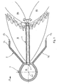
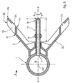
- This tube 1 is supplied with combustible gas 10 and is drilled with at least two holes 3 per burner block, aligned on the same generator 18 parallel therefore to the axis XX 'of the tube; a flame stabilizer 2 formed by two diverging wings 12 forming deflectors of on either side of said generator 18 is fixed on said tube 1.
- said deflector stabilizer 2 may include walls 13 1 , 13 2 forming reinforcing ribs at the ends, in the direction of axis XX ′, of the wings 12 of each burner block, as well as ribs 14 1 , 14 2 intermediate when the burner block has several holes 3 and therefore requires an intermediate reinforcement of the wings 2; these may include a break 22, towards their outer edges 17 downstream relative to the direction A of circulation of the oxidizing gases, to stiffen the latter and improve the aerodynamics of the burner block.
- At least one of said holes 3 is extended by a tube 11 extending beyond the outer edges 17 of the wings 12 and pierced with at least one 9 gas ejection port 10 fuel to sound distal end.
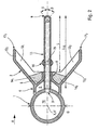
- the premix by Venturi system using a nozzle converging diverging 8 as shown in the Figure 2 and described in patent application EP 313 469 is not essential for the proper functioning of the burner: the present invention thus applies to all types of “vein” burners with stabilizer deflector, but including or not including such a device Venturi.
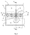
- the distal end of the tubing 11 has several divergent ejection orifices 9 whose ejection axes are inclined by an angle ⁇ by relation to plan AA 'defined by the generator 18 of alignment of the holes 3 and the axis XX ′ of the tube 1, and of a angle ⁇ with respect to the plane BB 'perpendicular to the previous and passing through hole 3 extended by said tubing 11.
- the number of orifices, their ejection angle ⁇ and ⁇ and their passage diameter are a function of the oxidizer speed and duct dimensions in which one has the burner, (and therefore the distance between the ramps that compose it), in order to be able adapt and optimize the penetration of fuel in the oxidizer vein.
- said distal end 25 of tubing 11 may be interchangeable and fixed by a threading system or other.
- their axes can be tilted two by two, with an angle ⁇ of 20 to 50 ° on either side of the plane AA ' and at an angle ⁇ of 10 to 30 ° on either side of the plane BB '.
- a burner block such as that shown in Figure 2 can be easily modified by adding parts complementary corresponding to these fins 24 and arranged beyond the break 22 of the wings 12 corresponding to edges 17: the position and dimensions of these fins 24 having a significant effect on the results it is interesting to have the possibility to change them if necessary thanks to their realization by added piece.
- the obstacle 15 possibly placed opposite one of the said holes 3 not extended by the pipe 11 can be worn, by a collar or fixing crown 16, on the tubing 11 with regard to the holes or orifices 3 ejection placed on either side thereof.
- said obstacle 15 is for example cylindrical and its axis is perpendicular to that of hole 3 opposite which it is disposed.
- this one may have at least three holes 3, one of which them 3 'is associated with the tubing 11, the obstacle 15 to a another hole 3 'adjacent to that associated with tubing 11 and the last hole is free.
- a burner block can have a number of holes in any fact, for example between two and ten and the tubing 11 can be arranged in a regular manner for example in every second hole, every third hole or one hole in four, etc ...
- the following burner block the invention comprises five holes 3 in which the tubing 11 is associated with the central hole, the two holes adjacent to it being associated with an obstacle 15 and the two end holes being free.
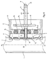
- Such burners according to the invention may also include elements characteristic of the burners, as described in patent EP 313 469, and such as in particular, in front of at least one hole 3 2 not extended by a pipe 11 and coaxial with that here, a diverging convergent nozzle 8 capable of causing the gas jet ejected through said hole 3 2 to create a vacuum at the inlet of the nozzle 8, as shown in FIG. 4.
- Said inlet communicates with the external face or extra back of at least one of the wings 12 of the stabilizer 2 through at least one opening 7.
- the space between the nozzles 8 and the tube 1 is closed by two wall elements 4 fixed on the tube and arranged almost parallel to the plane defined by the generator 18 for aligning the holes 3 and the axis XX 'of the tube 1 and by a front wall 5 connected to said wall elements 4 and carrying the nozzles; the openings 7 are drilled in said wall elements 4.
- the obstacle 15 may be a cylindrical tube with a diameter d 15 of approximately 10 mm and placed at a distance a of the order of 25 mm from the outlet of the nozzles 8; the length L 15 of such obstacles fixed on the pipe 11 can be of the order of 85 to 90 mm depending on the distance separating two adjacent holes or orifices 3; the diameter D 1 of the fuel supply tube is of the order of 85 to 90 mm.
Landscapes
- Engineering & Computer Science (AREA)
- Mechanical Engineering (AREA)
- General Engineering & Computer Science (AREA)
- Chemical & Material Sciences (AREA)
- Combustion & Propulsion (AREA)
- Environmental & Geological Engineering (AREA)
- Gas Burners (AREA)
Description
- introduire une partie du comburant à la racine de la flamme secondaire; ce dispositif a pour avantage, en plus de l'augmentation de la stabilité de la flamme lors du fonctionnement en gaz de turbine, de permettre une réduction de l'oxyde d'azote NO contenu dans ce gaz par effet dit de "reburning" (le NO est en effet transformé en N2 par réduction chimique venant des radicaux CH+ présents dans la racine de la flamme) ;
- rajouter au moins un obstacle disposé en face d'au moins un jet de gaz éjecté par un de ces trous non prolongés par une tubulure, ce qui favorise leur éclatement et élargit la flamme pilote dite également primaire pour y conférer une meilleure efficacité.
- la figure 1 est une vue en coupe d'un exemple de réalisation d'un brûleur selon l'invention perpendiculairement à l'axe de son tube d'alimentation en gaz combustible ;
- la figure 2 est une vue en coupe suivant II-II' de la figure 3 d'un autre exemple de réalisation d'un brûleur suivant l'invention ;
- la figure 3 est une vue frontale, face à l'écoulement du gaz à chauffer, du brûleur représenté sur la figure 2 ;
- la figure 4 est une vue en coupe suivant IV-IV' de la figure 3 d'un exemple de réalisation d'un brûleur suivant l'invention;
- la figure 5 est une vue en coupe suivant II, II' de la figure 3 d'un autre exemple de réalisation, que celui des figures 1 et 2, d'un brûleur suivant l'invention.
- éventuellement un obstacle 15 disposé en face d'un desdits trous 3 non prolongé par la tubulure 11 afin de favoriser l'éclatement des jets d'éjection de gaz combustible et élargir ainsi la flamme primaire pour lui conférer une meilleure efficacité;
- des ouvertures 21 au-delà des bords extérieurs 17 des ailes tels que définis précédemment et prolongés par des ailerons ou déflecteurs complémentaires 24, et réalisés dans ces dits ailerons 24 à un niveau intermédiaire par rapport à l'extrémité 23 aval de ceux-ci par rapport à la direction A de circulation des gaz comburants ; ces ouvertures 21 permettent le passage d'une partie de ce gaz comburant qui est alors introduit à la racine de la flamme secondaire 20, assurant une alimentation plus progressive de celles-ci, et permet une réduction du NO contenu dans ce gaz comburant.
Claims (12)
- Brûleur destiné à être placé dans un conduit pour chauffer un gaz circulant dans ce conduit, et comportant un tube (1) d'axe XX' apte à être disposé transversalement par rapport à la direction A de circulation dudit gaz, alimenté en gaz combustible (10) et percé d'au moins deux trous (3) alignés sur une même génératrice (18), et un stabilisateur de flamme (2) formé par deux ailes (12) divergentes formant déflecteur de part et d'autre de ladite génératrice (18), caractérisé en ce qu'au moins un desdits trous (3) est prolongé par une tubulure (11) s'étendant au-delà des bords extérieurs (17) des ailes (12) et percée d'au moins un orifice (9) d'éjection du gaz (10) combustible à son extrémité distale.
- Brûleur selon la revendication 1, caractérisé en ce que l'extrémité distale (25) de la tubulure (11) peut être interchangeable.
- Brûleur selon l'une des revendications 1 ou 2, caractérisé en ce que l'extrémité distale de la tubulure (11) comporte plusieurs orifices (9) d'éjection divergents.
- Brûleur selon la revendication 3, caractérisé en ce que l'extrémité distale (25) comporte au moins quatre orifices (9) d'éjection dont les axes sont inclinés d'un angle β de 20 à 50° de part et d'autre du plan défini par la génératrice (18) d'alignement des trous (3) et l'axe XX' du tube (1), et d'un angle α de 10 à 30° de part et d'autre du plan perpendiculaire au précédent et passant par le trou (3) prolongé par ladite tubulure (11).
- Brûleur selon l'une quelconque des revendications 1 à 4, caractérisé en ce qu'il comporte au moins un obstacle (15) disposé en face d'un des trous (3) non prolongé par la tubulure (11).
- Brûleur selon la revendication 5, caractérisé en ce que ledit obstacle (15) est porté par la tubulure (11) .
- Brûleur selon l'une quelconque des revendications 5 ou 6, caractérisé en ce que ledit obstacle (15) est cylindrique et son axe est perpendiculaire à celui du trou (3) en face duquel il est disposé.
- Brûleur selon l'une quelconque des revendications 5 à 7 et comprenant au moins trois trous (3) caractérisé en ce que la tubulure (11) est associé à un des trous (31) et l'obstacle (15) à un trou (32) adjacent à celui associé à la tubulure (11), le dernier trou étant libre.
- Brûleur selon l'une quelconque des revendications 5 à 8, et comprenant cinq trous (3) caractérisé en ce que la tubulure (11) est associée au trou central, les deux trous adjacents à celui-ci étant associés à un obstacle (15) et les deux trous d'extrémité étant libres.
- Brûleur selon l'une quelconque des revendications 1 à 9, caractérisé en ce qu'il comporte des ailerons complémentaires (24) prolongeant les bords extérieurs (17) des ailes et des ouvertures (21) réalisées dans ces ailerons (24) et aptes à laisser passer une partie du gaz circulant dans le conduit et l'introduire vers la racine de la flamme dudit brûleur.
- Brûleur selon l'une quelconque des revendications 1 à 10, caractérisé en ce qu'il comporte, devant au moins un trou (32) non prolongé par une tubulure (11) et coaxialement à celui-ci, une tuyère convergente-divergente (8) apte à ce que le jet de gaz éjecté par ledit trou (32) crée une dépression à l'entrée de la tuyère (8), ladite entrée communiquant avec la face extérieure d'au moins une des ailes (12) du stabilisateur (2) par au moins une ouverture (7).
- Brûleur selon la revendication 11, caractérisé en ce que l'espace entre les tuyères (8) et le tube (1) est fermé par deux éléments de paroi (4), fixés sur le tube et disposés quasi parallèles au plan défini par la génératrice (18) d'alignement des trous (3) et l'axe XX' du tube (1), et par une paroi frontale (5) raccordée auxdits éléments de paroi (4) et portant les tuyères (8), et en ce que les ouvertures (7) sont percées dans lesdits éléments de paroi (4).
Applications Claiming Priority (2)
| Application Number | Priority Date | Filing Date | Title |
|---|---|---|---|
| FR0001455A FR2804748B1 (fr) | 2000-02-04 | 2000-02-04 | Perfectionnement aux bruleurs a gaz pour le chauffage d'un gaz circulant dans un conduit |
| FR0001455 | 2000-02-04 |
Publications (2)
| Publication Number | Publication Date |
|---|---|
| EP1122494A1 EP1122494A1 (fr) | 2001-08-08 |
| EP1122494B1 true EP1122494B1 (fr) | 2004-04-14 |
Family
ID=8846686
Family Applications (1)
| Application Number | Title | Priority Date | Filing Date |
|---|---|---|---|
| EP00403424A Expired - Lifetime EP1122494B1 (fr) | 2000-02-04 | 2000-12-06 | Perfectionnement aux brûleurs à gaz pour le chauffage d'un gaz circulant dans un conduit |
Country Status (5)
| Country | Link |
|---|---|
| US (1) | US6409502B2 (fr) |
| EP (1) | EP1122494B1 (fr) |
| DE (1) | DE60009854D1 (fr) |
| ES (1) | ES2219282T3 (fr) |
| FR (1) | FR2804748B1 (fr) |
Families Citing this family (6)
| Publication number | Priority date | Publication date | Assignee | Title |
|---|---|---|---|---|
| US6929470B1 (en) * | 2002-10-30 | 2005-08-16 | Coen Company, Inc. | Low NOx duct burner |
| EP2045523B1 (fr) | 2007-10-02 | 2017-05-03 | AC Boilers S.p.A. | Brûleur de post-combustion pour gaz naturel et gaz pauvres avec une grande efficacité et une faible émission d'oxydes d'azote |
| EP2085695A1 (fr) * | 2008-01-29 | 2009-08-05 | Siemens Aktiengesellschaft | Buse à combustible dotée d'un canal à tourbillon et procédé de fabrication d'une buse à combustible |
| EP2218965A1 (fr) * | 2009-02-16 | 2010-08-18 | Total Petrochemicals Research Feluy | Brûleur à faible NOx |
| JP6018714B2 (ja) * | 2012-11-21 | 2016-11-02 | ゼネラル・エレクトリック・カンパニイ | コーキング防止液体燃料カートリッジ |
| BE1024480B1 (nl) * | 2016-08-08 | 2018-03-09 | Agrofrost, Naamloze Vennootschap | Gasbrander voor sterke luchtstroom |
Family Cites Families (10)
| Publication number | Priority date | Publication date | Assignee | Title |
|---|---|---|---|---|
| US3494712A (en) * | 1968-07-01 | 1970-02-10 | Coen Co | Duct burner |
| US3649211A (en) * | 1970-02-05 | 1972-03-14 | Coen Co | Air augmented duct burner |
| US3843309A (en) * | 1973-03-07 | 1974-10-22 | Gen Electric | Liquid fuel grid burner for vitiated air using auxiliary combustion air |
| US4375952A (en) * | 1979-09-07 | 1983-03-08 | Coen Company, Inc. | Wall fired duct heater |
| US4523905A (en) * | 1983-07-21 | 1985-06-18 | Nu-Way Energy Limited | Burner for gaseous fuels |
| JPS62123208A (ja) * | 1985-11-21 | 1987-06-04 | Hitachi Zosen Corp | 追焚き用低NOxダクトバ−ナ |
| US4767319A (en) * | 1987-03-27 | 1988-08-30 | Coen Company | Duct burner |
| FR2622277B1 (fr) | 1987-10-23 | 1990-02-23 | Mecanique Gle Foyers Turbine S | Bruleur a gaz pour le chauffage d'un courant d'air ou autre gaz comburant |
| DE3830038A1 (de) * | 1988-09-03 | 1990-03-08 | Gaswaerme Inst Ev | Brenner und verfahren zu seinem betreiben |
| EP0654637A1 (fr) * | 1993-11-19 | 1995-05-24 | GIERSCH GmbH | Brûleur à gaz |
-
2000
- 2000-02-04 FR FR0001455A patent/FR2804748B1/fr not_active Expired - Fee Related
- 2000-12-06 EP EP00403424A patent/EP1122494B1/fr not_active Expired - Lifetime
- 2000-12-06 ES ES00403424T patent/ES2219282T3/es not_active Expired - Lifetime
- 2000-12-06 DE DE60009854T patent/DE60009854D1/de not_active Expired - Lifetime
-
2001
- 2001-02-02 US US09/775,918 patent/US6409502B2/en not_active Expired - Fee Related
Also Published As
| Publication number | Publication date |
|---|---|
| ES2219282T3 (es) | 2004-12-01 |
| US6409502B2 (en) | 2002-06-25 |
| US20010012603A1 (en) | 2001-08-09 |
| FR2804748B1 (fr) | 2002-04-12 |
| FR2804748A1 (fr) | 2001-08-10 |
| DE60009854D1 (de) | 2004-05-19 |
| EP1122494A1 (fr) | 2001-08-08 |
Similar Documents
| Publication | Publication Date | Title |
|---|---|---|
| EP0675321B1 (fr) | Brûleurs à combustible gazeux à très faible émission d'oxyde d'azote | |
| EP3368826B1 (fr) | Systeme d'injection aerodynamique pour turbomachine d'aeronef, a melange air/carburant ameliore | |
| EP0911585A1 (fr) | Accroche-flamme carburé et refroidi | |
| EP1907754B1 (fr) | Procédé et installation de combustion de gaz combustible pauvre, sans soutien, à l'aide d'un brûleur et brûleur associé | |
| MC325A1 (fr) | Plaques rayonnantes pour brûleurs | |
| EP1122494B1 (fr) | Perfectionnement aux brûleurs à gaz pour le chauffage d'un gaz circulant dans un conduit | |
| EP1074790B1 (fr) | Brûleur à recirculation de fumées | |
| FR2706985A1 (fr) | ||
| FR2741424A1 (fr) | Bruleur a faible pollution, pour essais de puits petroliers | |
| EP0313469B1 (fr) | Brûleur à gaz pour le chauffage d'un courant d'air ou autre gaz comburant | |
| EP1058052B1 (fr) | Brûleur à combustible liquide à basse émission de NOx et de poussières et atomiseur associé | |
| EP3105506B1 (fr) | Module de brûleur en veine | |
| EP0926434A1 (fr) | Brûleur à faible émission d'oxyde d'azote avec circuit de gaz recyclé | |
| FR2909437A1 (fr) | Dispositif accroche-flammes, systemes de post-combustion et turboreacteur | |
| WO2018134501A2 (fr) | Chambre de combustion de turbomachine a haute permeabilite | |
| EP3234462B1 (fr) | Dispositif de combustion comprenant une enceinte de combustion a parois dites « froides », chaudière et four comportant un tel dispositif | |
| EP4004443A1 (fr) | Chambre de combustion comportant des systèmes d'injection secondaires et procédé d'alimentation en carburant | |
| FR2570473A1 (fr) | Perfectionnements aux bruleurs a gaz a ecoulement parallele comportant une rosace et un moyeu d'accrochage de flamme concernant les bruleurs a gaz et l'alimentation independante en air central | |
| EP0862018B1 (fr) | Dispositif de montage de brûleurs à l' intérieur d' un conduit de gaz | |
| EP1980788B1 (fr) | Brûleur à combustible gazeux | |
| FR2951525A1 (fr) | Procede de fonctionnement d'une chaudiere | |
| WO2016193608A1 (fr) | Four a injection sonique | |
| WO2025032142A1 (fr) | Bruleur, notamment pour section de prechauffage a flamme directe de ligne continue de traitement d'une bande metallique | |
| EP0162761B1 (fr) | Brûleur à ventelles à alimentation équilibrée en air secondaire | |
| FR2782150A1 (fr) | Perfectionnements aux bruleurs a recirculation de fumees et a faible emission d'oxydes d'azote |
Legal Events
| Date | Code | Title | Description |
|---|---|---|---|
| PUAI | Public reference made under article 153(3) epc to a published international application that has entered the european phase |
Free format text: ORIGINAL CODE: 0009012 |
|
| AK | Designated contracting states |
Kind code of ref document: A1 Designated state(s): DE ES IT NL |
|
| AX | Request for extension of the european patent |
Free format text: AL;LT;LV;MK;RO;SI |
|
| 17P | Request for examination filed |
Effective date: 20010824 |
|
| AKX | Designation fees paid |
Free format text: DE ES IT NL |
|
| GRAP | Despatch of communication of intention to grant a patent |
Free format text: ORIGINAL CODE: EPIDOSNIGR1 |
|
| GRAS | Grant fee paid |
Free format text: ORIGINAL CODE: EPIDOSNIGR3 |
|
| GRAA | (expected) grant |
Free format text: ORIGINAL CODE: 0009210 |
|
| AK | Designated contracting states |
Kind code of ref document: B1 Designated state(s): DE ES IT NL |
|
| REF | Corresponds to: |
Ref document number: 60009854 Country of ref document: DE Date of ref document: 20040519 Kind code of ref document: P |
|
| PG25 | Lapsed in a contracting state [announced via postgrant information from national office to epo] |
Ref country code: DE Free format text: LAPSE BECAUSE OF FAILURE TO SUBMIT A TRANSLATION OF THE DESCRIPTION OR TO PAY THE FEE WITHIN THE PRESCRIBED TIME-LIMIT Effective date: 20040715 |
|
| REG | Reference to a national code |
Ref country code: ES Ref legal event code: FG2A Ref document number: 2219282 Country of ref document: ES Kind code of ref document: T3 |
|
| PGFP | Annual fee paid to national office [announced via postgrant information from national office to epo] |
Ref country code: NL Payment date: 20041205 Year of fee payment: 5 |
|
| PLBE | No opposition filed within time limit |
Free format text: ORIGINAL CODE: 0009261 |
|
| STAA | Information on the status of an ep patent application or granted ep patent |
Free format text: STATUS: NO OPPOSITION FILED WITHIN TIME LIMIT |
|
| 26N | No opposition filed |
Effective date: 20050117 |
|
| PG25 | Lapsed in a contracting state [announced via postgrant information from national office to epo] |
Ref country code: NL Free format text: LAPSE BECAUSE OF NON-PAYMENT OF DUE FEES Effective date: 20060701 |
|
| NLV4 | Nl: lapsed or anulled due to non-payment of the annual fee |
Effective date: 20060701 |
|
| PGFP | Annual fee paid to national office [announced via postgrant information from national office to epo] |
Ref country code: IT Payment date: 20071228 Year of fee payment: 8 |
|
| PG25 | Lapsed in a contracting state [announced via postgrant information from national office to epo] |
Ref country code: IT Free format text: LAPSE BECAUSE OF NON-PAYMENT OF DUE FEES Effective date: 20081206 |
|
| PGFP | Annual fee paid to national office [announced via postgrant information from national office to epo] |
Ref country code: ES Payment date: 20190102 Year of fee payment: 19 |
|
| REG | Reference to a national code |
Ref country code: ES Ref legal event code: FD2A Effective date: 20210531 |
|
| PG25 | Lapsed in a contracting state [announced via postgrant information from national office to epo] |
Ref country code: ES Free format text: LAPSE BECAUSE OF NON-PAYMENT OF DUE FEES Effective date: 20191207 |