EP1122143A1 - Deckel - Google Patents
Deckel Download PDFInfo
- Publication number
- EP1122143A1 EP1122143A1 EP01100148A EP01100148A EP1122143A1 EP 1122143 A1 EP1122143 A1 EP 1122143A1 EP 01100148 A EP01100148 A EP 01100148A EP 01100148 A EP01100148 A EP 01100148A EP 1122143 A1 EP1122143 A1 EP 1122143A1
- Authority
- EP
- European Patent Office
- Prior art keywords
- cover
- lid
- blind holes
- bottom piece
- vent
- Prior art date
- Legal status (The legal status is an assumption and is not a legal conclusion. Google has not performed a legal analysis and makes no representation as to the accuracy of the status listed.)
- Withdrawn
Links
- 238000009423 ventilation Methods 0.000 claims abstract description 15
- 239000011248 coating agent Substances 0.000 claims description 3
- 238000000576 coating method Methods 0.000 claims description 3
- 238000009833 condensation Methods 0.000 abstract description 3
- 230000005494 condensation Effects 0.000 abstract description 3
- 239000000463 material Substances 0.000 description 12
- 238000000034 method Methods 0.000 description 10
- 238000009434 installation Methods 0.000 description 6
- 238000004519 manufacturing process Methods 0.000 description 5
- 238000004049 embossing Methods 0.000 description 4
- XLYOFNOQVPJJNP-UHFFFAOYSA-N water Substances O XLYOFNOQVPJJNP-UHFFFAOYSA-N 0.000 description 3
- 239000003570 air Substances 0.000 description 2
- 230000007797 corrosion Effects 0.000 description 2
- 238000005260 corrosion Methods 0.000 description 2
- 230000006735 deficit Effects 0.000 description 2
- 238000005516 engineering process Methods 0.000 description 2
- 230000035515 penetration Effects 0.000 description 2
- 238000004080 punching Methods 0.000 description 2
- 238000000926 separation method Methods 0.000 description 2
- 239000012080 ambient air Substances 0.000 description 1
- 238000013459 approach Methods 0.000 description 1
- 230000009286 beneficial effect Effects 0.000 description 1
- 230000015572 biosynthetic process Effects 0.000 description 1
- 230000006835 compression Effects 0.000 description 1
- 238000007906 compression Methods 0.000 description 1
- 238000011161 development Methods 0.000 description 1
- 230000018109 developmental process Effects 0.000 description 1
- 238000005553 drilling Methods 0.000 description 1
- 230000000694 effects Effects 0.000 description 1
- 230000007613 environmental effect Effects 0.000 description 1
- 239000012530 fluid Substances 0.000 description 1
- 230000007774 longterm Effects 0.000 description 1
- 238000003801 milling Methods 0.000 description 1
- 238000003825 pressing Methods 0.000 description 1
- 238000004064 recycling Methods 0.000 description 1
- 230000001105 regulatory effect Effects 0.000 description 1
- 238000007789 sealing Methods 0.000 description 1
- 238000004381 surface treatment Methods 0.000 description 1
- 238000003466 welding Methods 0.000 description 1
Images
Classifications
-
- B—PERFORMING OPERATIONS; TRANSPORTING
- B60—VEHICLES IN GENERAL
- B60T—VEHICLE BRAKE CONTROL SYSTEMS OR PARTS THEREOF; BRAKE CONTROL SYSTEMS OR PARTS THEREOF, IN GENERAL; ARRANGEMENT OF BRAKING ELEMENTS ON VEHICLES IN GENERAL; PORTABLE DEVICES FOR PREVENTING UNWANTED MOVEMENT OF VEHICLES; VEHICLE MODIFICATIONS TO FACILITATE COOLING OF BRAKES
- B60T17/00—Component parts, details, or accessories of power brake systems not covered by groups B60T8/00, B60T13/00 or B60T15/00, or presenting other characteristic features
- B60T17/08—Brake cylinders other than ultimate actuators
Definitions
- the invention relates to a cover with a vent, which in particular is provided for a brake cylinder on a commercial vehicle.
- DE 28 09 399 B2 An example of a lid with a vent opening is in the DE 28 09 399 B2 describes, which deals with the problem, one Pressure equalization in the container interior, which is otherwise sealed off from the ambient air a brake fluid reservoir for the master cylinder to enable hydraulic braking system.
- DE 197 12 209 A1 also discloses a hydraulic unit for a hydraulic control and / or regulating device in the Cavities can be ventilated via a pressure compensation opening.
- the one Pot-shaped lid provided electrical drive element is on a metallic Valve block placed tightly on the outside. The required ventilation there are cavities between the housing and the valve block usually via a pressure equalization opening in the housing cover.
- the invention is therefore based on the object of a cover with a ventilation opening to further develop such that it can be adjusted with less assembly effort to the respective installation position.
- This object is achieved according to the invention by developing a cover with a Vent opening solved in such a way that a plurality of blind holes on the lid is formed, and that a bottom piece of a selected blind hole for manufacture the vent is removable.
- the measure according to the invention is uniform Appearance of the lid, i.e. no visually disturbing plastic plugs on the lid.
- the removal of the bottom piece at the selected blind hole can be from the time take place from which the installation position of the arrangement is known. At predetermined Series can do this already in the course of installing the cover z. B. on the brake cylinder respectively.
- the entire arrangement is sent directly to a customer as a spare part Given that the installation itself is carried out, this can open the ventilation opening can also be carried out directly on site after installation.
- the bottom pieces of the blind holes can also go out over the outer surface protrude from the lid.
- the blind holes are embossed. Then the bottom piece is still connected to the cover via a material web, whereby a reliable connection is given.
- the Determine the embossing process very precisely, which force input is required to detach the base from the lid. The embossing process is therefore very suitable good, on the one hand to achieve a reliable hold of the base piece on the lid, how it is of long-term importance for the unused blind holes, and on the other hand allow the selected bottom piece to be cut with little force to to form the ventilation opening.
- the blind holes are punched, i.e. only up to one limited dimensions are punched through the material of the lid.
- a pressing by means of which a partial area of the base piece on the cover is set.
- the stamping process is characterized by a lower process technology Effort out.
- this embodiment is the one for removal the force required for the base piece is usually less than with the embossing process, since the material bond between the base piece and the lid is essentially eliminated is.
- cover is also coated at least on the outside, can be achieved in addition to the inherent purpose as corrosion protection etc. that e.g. hairline cracks that may have occurred in the manufacture of the blind holes Area of the blind holes to be closed.
- corrosion protection etc. e.g. hairline cracks that may have occurred in the manufacture of the blind holes Area of the blind holes to be closed.
- the coating therefore increases safety against an undesirable loss of a piece of ground.
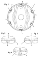
- a plan view of a lid 1 is shown, as e.g. on a brake cylinder is arranged.
- the cover 1 has five Blind holes 2 and a vent 3.
- the blind holes 2 or the ventilation opening 3 are arranged evenly spaced on the circumference of the cover 1.
- the blind holes 2 continue to have a bottom piece 4, while this at the vent 3 in Has been removed during assembly.
- the blind holes 2 are thus still tightly closed, so that the penetration of moisture, dirt etc. is effectively avoided becomes.
- FIG. 2 An example of an embossed blind hole 2 is shown in more detail in FIG. 2. Out this figure it is clear that the bottom piece 4 continues over a narrow web is connected to the material of the lid 1. This web of material serves as a predetermined breaking point, if the bottom piece 4 is to be separated. The force required for this can by dimensioning the web width taking into account the material properties can be easily preset.
- FIG 3 shows in detail an example of a blind hole 2 with a stamped-in base piece 4.
- the bottom piece 4 is caused by the compression occurring in the course of the stamping process held on the lid 1.
- the degree of overlap of the bottom piece 4 with the Material thickness of the lid 1 is determined and set by the punching process, so that the force required to detach the base piece 4 can also be preset.
- the bottom piece 4 is consequently separated from the outside.
- the necessary for this Force can be either at a predetermined position of the vent 3 before mounting the Cover 1 are applied from the inside, or it is after assembly possible to grip the protruding bottom piece 4 from outside with a pair of pliers etc. and pull outwards.
- the cover 1 provided with the blind holes 2 can also do all the usual other Processes such as surface treatments, welding processes, etc. subjected become. Possibly aftertreatment of the bottom piece 4, an aftertreatment be made at the vent 3 to prevent possible corrosion in particular in the area of the previously existing web between the bottom piece 4 and to avoid the lid 1.
- the number of prefabricated blind holes 2 is not limited to the six shown here Limited pieces. It can be varied depending on the application. It will be like this chosen that a variety of designs is covered, which increases the number can significantly reduce different lid designs for a product group. As a rule, between two and eight blind holes are provided, including these can be distributed unevenly on the lid.
- the lid 1 according to the invention can also be used on any other arrangement can be used as a brake cylinder provided a vent is provided. It is also possible, e.g. that of the vent 3 opposite open hole to open, for example, an air intake at the to allow highest point of the arrangement.
- the bottom piece can also be designed so that it is in relation to Material thickness of the lid 1 has a smaller thickness. Hence it is possible to design the bottom piece so that it does not over the outer circumference of the Cover 1 survives, but merely represents a "material weak point" which can be broken with relatively little force. It is also possible to to provide the bottom piece in the area of the inner surface of the cover 1. Moreover the bottom piece can also be pressed into the interior of the cover 1, if there is no impairment of the function of the components arranged in the cover 1 is to be expected.
- blind holes 2 in a different way than by embossing or Stamping can be made.
- a drilling or milling process or a other methods of separation or deformation are possible in order to make these pre-dimensioned, spatial to form clearly limited "material weaknesses" in the lid 1.
- the invention thus creates a cover provided in particular for brake cylinders 1 with a vent 3 for draining condensate etc. on the lid 1 is initially a plurality of blind holes 2 in the course of production prefabricated, with a bottom piece 4 of a selected blind hole 2 for manufacture the vent 3 is separable.
- This advantageously ensures that only the ventilation opening 3 is open, while the other blind holes 2 exist i.e. stay closed. This simplifies the assembly of the invention Cover 1 essential, since no openings are closed by grafting, etc. have to.
Landscapes
- Engineering & Computer Science (AREA)
- Transportation (AREA)
- Mechanical Engineering (AREA)
- Braking Arrangements (AREA)
- Closures For Containers (AREA)
Abstract
Description
Claims (5)
- Deckel (1), insbesondere für einen Bremszylinder an einem Nutzfahrzeug, mit einer Entlüftungsöffnung (3), dadurch gekennzeichnet, daß am Deckel (1) eine Mehrzahl von Sacklöchern (2) vorausgebildet ist, und daß ein Bodenstück (4) eines ausgewählten Sacklochs (2) zur Herstellung der Entlüftungsöffnung (3) entfernbar ist.
- Deckel nach Anspruch 1, dadurch gekennzeichnet, daß die Bodenstücke (4) der Sacklöcher (2) nach außen über die Außenfläche des Deckels (1) überstehen.
- Deckel nach Anspruch 1 oder 2, dadurch gekennzeichnet, daß die Sacklöcher (2) eingeprägt sind.
- Deckel nach Anspruch 1 oder 2, dadurch gekennzeichnet, daß die Sacklöcher (2) eingestanzt sind.
- Deckel nach einem der Ansprüche 1 bis 4, dadurch gekennzeichnet, daß er wenigstens außenseitig mit einer Beschichtung versehen ist.
Applications Claiming Priority (2)
| Application Number | Priority Date | Filing Date | Title |
|---|---|---|---|
| DE2000104094 DE10004094C1 (de) | 2000-01-31 | 2000-01-31 | Deckel |
| DE10004094 | 2000-01-31 |
Publications (1)
| Publication Number | Publication Date |
|---|---|
| EP1122143A1 true EP1122143A1 (de) | 2001-08-08 |
Family
ID=7629291
Family Applications (1)
| Application Number | Title | Priority Date | Filing Date |
|---|---|---|---|
| EP01100148A Withdrawn EP1122143A1 (de) | 2000-01-31 | 2001-01-16 | Deckel |
Country Status (3)
| Country | Link |
|---|---|
| EP (1) | EP1122143A1 (de) |
| DE (1) | DE10004094C1 (de) |
| TR (1) | TR200100321A2 (de) |
Cited By (1)
| Publication number | Priority date | Publication date | Assignee | Title |
|---|---|---|---|---|
| US20160146274A1 (en) * | 2013-06-28 | 2016-05-26 | Wabco Europe Bvba | Brake cylinder |
Citations (3)
| Publication number | Priority date | Publication date | Assignee | Title |
|---|---|---|---|---|
| EP0126874A1 (de) * | 1983-04-27 | 1984-12-05 | Knorr-Bremse Ag | Druckluftzylinder, insbesondere Druckluftbremszylinder für Kraftfahrzeuge |
| EP0279930A1 (de) * | 1987-02-12 | 1988-08-31 | WABCO Westinghouse Fahrzeugbremsen GmbH | Beatmungsvorrichtung für einen Federspeicherbremszylinder |
| WO1996026093A1 (en) * | 1995-02-21 | 1996-08-29 | Nai Anchorlok, Inc. | Spring brake actuator with filtered vent openings |
Family Cites Families (2)
| Publication number | Priority date | Publication date | Assignee | Title |
|---|---|---|---|---|
| JPS5819970Y2 (ja) * | 1977-03-08 | 1983-04-25 | トヨタ自動車株式会社 | 密封式液体リザ−バ |
| DE19712209A1 (de) * | 1997-03-24 | 1998-10-01 | Itt Mfg Enterprises Inc | Hydraulikaggregat für hydraulische Steuer- und/oder Regelvorrichtung |
-
2000
- 2000-01-31 DE DE2000104094 patent/DE10004094C1/de not_active Expired - Fee Related
-
2001
- 2001-01-16 EP EP01100148A patent/EP1122143A1/de not_active Withdrawn
- 2001-01-31 TR TR2001/00321A patent/TR200100321A2/xx unknown
Patent Citations (3)
| Publication number | Priority date | Publication date | Assignee | Title |
|---|---|---|---|---|
| EP0126874A1 (de) * | 1983-04-27 | 1984-12-05 | Knorr-Bremse Ag | Druckluftzylinder, insbesondere Druckluftbremszylinder für Kraftfahrzeuge |
| EP0279930A1 (de) * | 1987-02-12 | 1988-08-31 | WABCO Westinghouse Fahrzeugbremsen GmbH | Beatmungsvorrichtung für einen Federspeicherbremszylinder |
| WO1996026093A1 (en) * | 1995-02-21 | 1996-08-29 | Nai Anchorlok, Inc. | Spring brake actuator with filtered vent openings |
Cited By (2)
| Publication number | Priority date | Publication date | Assignee | Title |
|---|---|---|---|---|
| US20160146274A1 (en) * | 2013-06-28 | 2016-05-26 | Wabco Europe Bvba | Brake cylinder |
| US10197118B2 (en) * | 2013-06-28 | 2019-02-05 | Wabco Europe Bvba | Brake cylinder |
Also Published As
| Publication number | Publication date |
|---|---|
| DE10004094C1 (de) | 2001-08-16 |
| TR200100321A3 (tr) | 2001-09-21 |
| TR200100321A2 (tr) | 2001-09-21 |
Similar Documents
| Publication | Publication Date | Title |
|---|---|---|
| DE60101414T2 (de) | Hydraulikspeicherentlüftung und ihre Herstellung | |
| EP3025077B2 (de) | Membran und verfahren zu deren herstellung | |
| EP2932811B1 (de) | Anordnung zum druckausgleich eines gehäuses | |
| EP4190135B1 (de) | Explosionsgesichertes gehäuse für ein leistungselektronisches gerät | |
| DE19755765A1 (de) | Gehäuse mit Deckel | |
| WO2021156094A1 (de) | Abdeckstruktur und smc-werkzeug sowie verfahren zum herstellen einer derartigen abdeckstruktur | |
| DE102009041417A1 (de) | Verschlussstopfenanordnung für einen Akkumulator | |
| DE102018118660B4 (de) | Elektronische Vorrichtung, die an einer Industriemaschine angebracht ist | |
| DE4329055A1 (de) | Druckdichter Wandler für Kraftfahrzeuge | |
| DE10004094C1 (de) | Deckel | |
| EP2943697A1 (de) | Scheibenbremse für ein nutzfahrzeug | |
| DE4242861A1 (de) | Einrichtung zum Erfassen des Reifendruckes eines Kraftfahrzeugrades | |
| DE102013203408B4 (de) | Verfahren zum Kaschieren eines Bauteils durch ein Kaschierwerkzeug mit einem Kaschierelement | |
| DE102011018796B3 (de) | Gehäusedurchführung | |
| DE19708006C2 (de) | Hydraulisches Steuerungssystem | |
| WO1999052727A1 (de) | Verschlusselement für öffnungen in fahrzeugtüren | |
| DE69414483T2 (de) | Lagerdichtungsplatte und ihr Herstellungsverfahren | |
| DE102021118189B4 (de) | ABDECKUNG FÜR EINE DRUCKBEGRENZUNGSVENTILANORDNUNG EINES FAHRZEUGS und DRUCKBEGRENZUNGSVENTILANORDNUNG MIT EINER SOLCHEN ABDECKUNG | |
| DE202007017752U1 (de) | Steckerbrücke mit Steckerhohlstift | |
| EP1168903B1 (de) | Gehäuseeinheit für elektrische Komponenten zum Einsatz im Kraftfahrzeugbereich | |
| DE4413322C2 (de) | Entlüftungs-Druckregelventil für ein Brennkraftmaschinen-Kurbelgehäuse | |
| EP0286810B1 (de) | Verfahren zum Herstellen eines Ventils, insbesondere eines thermostatischen Ventils | |
| EP2240288B1 (de) | Verfahren zum bedarfsweisen erzeugen eines durchbruchs in einem karosserieabschnitt eines fahrzeugs | |
| DE102007013875B3 (de) | Ventil mit Druckschott | |
| DE102013112529B4 (de) | Mit einer seitlichen Bearbeitungsöffnung versehener Bremssattel einer Scheibenbremse |
Legal Events
| Date | Code | Title | Description |
|---|---|---|---|
| PUAI | Public reference made under article 153(3) epc to a published international application that has entered the european phase |
Free format text: ORIGINAL CODE: 0009012 |
|
| AK | Designated contracting states |
Kind code of ref document: A1 Designated state(s): AT BE CH CY DE DK ES FI FR GB GR IE IT LI LU MC NL PT SE TR Kind code of ref document: A1 Designated state(s): DE ES FR GB IT SE |
|
| AX | Request for extension of the european patent |
Free format text: AL;LT;LV;MK;RO;SI |
|
| 17P | Request for examination filed |
Effective date: 20020208 |
|
| AKX | Designation fees paid |
Free format text: DE ES FR GB IT SE |
|
| RBV | Designated contracting states (corrected) |
Designated state(s): AT BE CH CY DE DK ES FI FR GB GR IE IT LI LU MC NL PT SE TR |
|
| RBV | Designated contracting states (corrected) |
Designated state(s): DE ES FR GB IT SE |
|
| STAA | Information on the status of an ep patent application or granted ep patent |
Free format text: STATUS: THE APPLICATION HAS BEEN WITHDRAWN |
|
| 18W | Application withdrawn |
Effective date: 20041115 |