EP1122111B1 - A power transmission apparatus for hybrid vehicles - Google Patents
A power transmission apparatus for hybrid vehicles Download PDFInfo
- Publication number
- EP1122111B1 EP1122111B1 EP00118265A EP00118265A EP1122111B1 EP 1122111 B1 EP1122111 B1 EP 1122111B1 EP 00118265 A EP00118265 A EP 00118265A EP 00118265 A EP00118265 A EP 00118265A EP 1122111 B1 EP1122111 B1 EP 1122111B1
- Authority
- EP
- European Patent Office
- Prior art keywords
- engine
- gear
- motor generator
- clutch
- gear change
- Prior art date
- Legal status (The legal status is an assumption and is not a legal conclusion. Google has not performed a legal analysis and makes no representation as to the accuracy of the status listed.)
- Expired - Lifetime
Links
Images


Classifications
-
- B—PERFORMING OPERATIONS; TRANSPORTING
- B60—VEHICLES IN GENERAL
- B60K—ARRANGEMENT OR MOUNTING OF PROPULSION UNITS OR OF TRANSMISSIONS IN VEHICLES; ARRANGEMENT OR MOUNTING OF PLURAL DIVERSE PRIME-MOVERS IN VEHICLES; AUXILIARY DRIVES FOR VEHICLES; INSTRUMENTATION OR DASHBOARDS FOR VEHICLES; ARRANGEMENTS IN CONNECTION WITH COOLING, AIR INTAKE, GAS EXHAUST OR FUEL SUPPLY OF PROPULSION UNITS IN VEHICLES
- B60K17/00—Arrangement or mounting of transmissions in vehicles
- B60K17/02—Arrangement or mounting of transmissions in vehicles characterised by arrangement, location, or kind of clutch
-
- B—PERFORMING OPERATIONS; TRANSPORTING
- B60—VEHICLES IN GENERAL
- B60W—CONJOINT CONTROL OF VEHICLE SUB-UNITS OF DIFFERENT TYPE OR DIFFERENT FUNCTION; CONTROL SYSTEMS SPECIALLY ADAPTED FOR HYBRID VEHICLES; ROAD VEHICLE DRIVE CONTROL SYSTEMS FOR PURPOSES NOT RELATED TO THE CONTROL OF A PARTICULAR SUB-UNIT
- B60W20/00—Control systems specially adapted for hybrid vehicles
-
- B—PERFORMING OPERATIONS; TRANSPORTING
- B60—VEHICLES IN GENERAL
- B60K—ARRANGEMENT OR MOUNTING OF PROPULSION UNITS OR OF TRANSMISSIONS IN VEHICLES; ARRANGEMENT OR MOUNTING OF PLURAL DIVERSE PRIME-MOVERS IN VEHICLES; AUXILIARY DRIVES FOR VEHICLES; INSTRUMENTATION OR DASHBOARDS FOR VEHICLES; ARRANGEMENTS IN CONNECTION WITH COOLING, AIR INTAKE, GAS EXHAUST OR FUEL SUPPLY OF PROPULSION UNITS IN VEHICLES
- B60K6/00—Arrangement or mounting of plural diverse prime-movers for mutual or common propulsion, e.g. hybrid propulsion systems comprising electric motors and internal combustion engines ; Control systems therefor, i.e. systems controlling two or more prime movers, or controlling one of these prime movers and any of the transmission, drive or drive units Informative references: mechanical gearings with secondary electric drive F16H3/72; arrangements for handling mechanical energy structurally associated with the dynamo-electric machine H02K7/00; machines comprising structurally interrelated motor and generator parts H02K51/00; dynamo-electric machines not otherwise provided for in H02K see H02K99/00
- B60K6/20—Arrangement or mounting of plural diverse prime-movers for mutual or common propulsion, e.g. hybrid propulsion systems comprising electric motors and internal combustion engines ; Control systems therefor, i.e. systems controlling two or more prime movers, or controlling one of these prime movers and any of the transmission, drive or drive units Informative references: mechanical gearings with secondary electric drive F16H3/72; arrangements for handling mechanical energy structurally associated with the dynamo-electric machine H02K7/00; machines comprising structurally interrelated motor and generator parts H02K51/00; dynamo-electric machines not otherwise provided for in H02K see H02K99/00 the prime-movers consisting of electric motors and internal combustion engines, e.g. HEVs
- B60K6/42—Arrangement or mounting of plural diverse prime-movers for mutual or common propulsion, e.g. hybrid propulsion systems comprising electric motors and internal combustion engines ; Control systems therefor, i.e. systems controlling two or more prime movers, or controlling one of these prime movers and any of the transmission, drive or drive units Informative references: mechanical gearings with secondary electric drive F16H3/72; arrangements for handling mechanical energy structurally associated with the dynamo-electric machine H02K7/00; machines comprising structurally interrelated motor and generator parts H02K51/00; dynamo-electric machines not otherwise provided for in H02K see H02K99/00 the prime-movers consisting of electric motors and internal combustion engines, e.g. HEVs characterised by the architecture of the hybrid electric vehicle
- B60K6/44—Series-parallel type
- B60K6/442—Series-parallel switching type
-
- B—PERFORMING OPERATIONS; TRANSPORTING
- B60—VEHICLES IN GENERAL
- B60K—ARRANGEMENT OR MOUNTING OF PROPULSION UNITS OR OF TRANSMISSIONS IN VEHICLES; ARRANGEMENT OR MOUNTING OF PLURAL DIVERSE PRIME-MOVERS IN VEHICLES; AUXILIARY DRIVES FOR VEHICLES; INSTRUMENTATION OR DASHBOARDS FOR VEHICLES; ARRANGEMENTS IN CONNECTION WITH COOLING, AIR INTAKE, GAS EXHAUST OR FUEL SUPPLY OF PROPULSION UNITS IN VEHICLES
- B60K6/00—Arrangement or mounting of plural diverse prime-movers for mutual or common propulsion, e.g. hybrid propulsion systems comprising electric motors and internal combustion engines ; Control systems therefor, i.e. systems controlling two or more prime movers, or controlling one of these prime movers and any of the transmission, drive or drive units Informative references: mechanical gearings with secondary electric drive F16H3/72; arrangements for handling mechanical energy structurally associated with the dynamo-electric machine H02K7/00; machines comprising structurally interrelated motor and generator parts H02K51/00; dynamo-electric machines not otherwise provided for in H02K see H02K99/00
- B60K6/20—Arrangement or mounting of plural diverse prime-movers for mutual or common propulsion, e.g. hybrid propulsion systems comprising electric motors and internal combustion engines ; Control systems therefor, i.e. systems controlling two or more prime movers, or controlling one of these prime movers and any of the transmission, drive or drive units Informative references: mechanical gearings with secondary electric drive F16H3/72; arrangements for handling mechanical energy structurally associated with the dynamo-electric machine H02K7/00; machines comprising structurally interrelated motor and generator parts H02K51/00; dynamo-electric machines not otherwise provided for in H02K see H02K99/00 the prime-movers consisting of electric motors and internal combustion engines, e.g. HEVs
- B60K6/42—Arrangement or mounting of plural diverse prime-movers for mutual or common propulsion, e.g. hybrid propulsion systems comprising electric motors and internal combustion engines ; Control systems therefor, i.e. systems controlling two or more prime movers, or controlling one of these prime movers and any of the transmission, drive or drive units Informative references: mechanical gearings with secondary electric drive F16H3/72; arrangements for handling mechanical energy structurally associated with the dynamo-electric machine H02K7/00; machines comprising structurally interrelated motor and generator parts H02K51/00; dynamo-electric machines not otherwise provided for in H02K see H02K99/00 the prime-movers consisting of electric motors and internal combustion engines, e.g. HEVs characterised by the architecture of the hybrid electric vehicle
- B60K6/48—Parallel type
-
- B—PERFORMING OPERATIONS; TRANSPORTING
- B60—VEHICLES IN GENERAL
- B60K—ARRANGEMENT OR MOUNTING OF PROPULSION UNITS OR OF TRANSMISSIONS IN VEHICLES; ARRANGEMENT OR MOUNTING OF PLURAL DIVERSE PRIME-MOVERS IN VEHICLES; AUXILIARY DRIVES FOR VEHICLES; INSTRUMENTATION OR DASHBOARDS FOR VEHICLES; ARRANGEMENTS IN CONNECTION WITH COOLING, AIR INTAKE, GAS EXHAUST OR FUEL SUPPLY OF PROPULSION UNITS IN VEHICLES
- B60K6/00—Arrangement or mounting of plural diverse prime-movers for mutual or common propulsion, e.g. hybrid propulsion systems comprising electric motors and internal combustion engines ; Control systems therefor, i.e. systems controlling two or more prime movers, or controlling one of these prime movers and any of the transmission, drive or drive units Informative references: mechanical gearings with secondary electric drive F16H3/72; arrangements for handling mechanical energy structurally associated with the dynamo-electric machine H02K7/00; machines comprising structurally interrelated motor and generator parts H02K51/00; dynamo-electric machines not otherwise provided for in H02K see H02K99/00
- B60K6/20—Arrangement or mounting of plural diverse prime-movers for mutual or common propulsion, e.g. hybrid propulsion systems comprising electric motors and internal combustion engines ; Control systems therefor, i.e. systems controlling two or more prime movers, or controlling one of these prime movers and any of the transmission, drive or drive units Informative references: mechanical gearings with secondary electric drive F16H3/72; arrangements for handling mechanical energy structurally associated with the dynamo-electric machine H02K7/00; machines comprising structurally interrelated motor and generator parts H02K51/00; dynamo-electric machines not otherwise provided for in H02K see H02K99/00 the prime-movers consisting of electric motors and internal combustion engines, e.g. HEVs
- B60K6/50—Architecture of the driveline characterised by arrangement or kind of transmission units
- B60K6/54—Transmission for changing ratio
- B60K6/547—Transmission for changing ratio the transmission being a stepped gearing
-
- B—PERFORMING OPERATIONS; TRANSPORTING
- B60—VEHICLES IN GENERAL
- B60W—CONJOINT CONTROL OF VEHICLE SUB-UNITS OF DIFFERENT TYPE OR DIFFERENT FUNCTION; CONTROL SYSTEMS SPECIALLY ADAPTED FOR HYBRID VEHICLES; ROAD VEHICLE DRIVE CONTROL SYSTEMS FOR PURPOSES NOT RELATED TO THE CONTROL OF A PARTICULAR SUB-UNIT
- B60W10/00—Conjoint control of vehicle sub-units of different type or different function
- B60W10/02—Conjoint control of vehicle sub-units of different type or different function including control of driveline clutches
-
- B—PERFORMING OPERATIONS; TRANSPORTING
- B60—VEHICLES IN GENERAL
- B60W—CONJOINT CONTROL OF VEHICLE SUB-UNITS OF DIFFERENT TYPE OR DIFFERENT FUNCTION; CONTROL SYSTEMS SPECIALLY ADAPTED FOR HYBRID VEHICLES; ROAD VEHICLE DRIVE CONTROL SYSTEMS FOR PURPOSES NOT RELATED TO THE CONTROL OF A PARTICULAR SUB-UNIT
- B60W10/00—Conjoint control of vehicle sub-units of different type or different function
- B60W10/04—Conjoint control of vehicle sub-units of different type or different function including control of propulsion units
- B60W10/06—Conjoint control of vehicle sub-units of different type or different function including control of propulsion units including control of combustion engines
-
- B—PERFORMING OPERATIONS; TRANSPORTING
- B60—VEHICLES IN GENERAL
- B60W—CONJOINT CONTROL OF VEHICLE SUB-UNITS OF DIFFERENT TYPE OR DIFFERENT FUNCTION; CONTROL SYSTEMS SPECIALLY ADAPTED FOR HYBRID VEHICLES; ROAD VEHICLE DRIVE CONTROL SYSTEMS FOR PURPOSES NOT RELATED TO THE CONTROL OF A PARTICULAR SUB-UNIT
- B60W10/00—Conjoint control of vehicle sub-units of different type or different function
- B60W10/04—Conjoint control of vehicle sub-units of different type or different function including control of propulsion units
- B60W10/08—Conjoint control of vehicle sub-units of different type or different function including control of propulsion units including control of electric propulsion units, e.g. motors or generators
-
- B—PERFORMING OPERATIONS; TRANSPORTING
- B60—VEHICLES IN GENERAL
- B60W—CONJOINT CONTROL OF VEHICLE SUB-UNITS OF DIFFERENT TYPE OR DIFFERENT FUNCTION; CONTROL SYSTEMS SPECIALLY ADAPTED FOR HYBRID VEHICLES; ROAD VEHICLE DRIVE CONTROL SYSTEMS FOR PURPOSES NOT RELATED TO THE CONTROL OF A PARTICULAR SUB-UNIT
- B60W10/00—Conjoint control of vehicle sub-units of different type or different function
- B60W10/10—Conjoint control of vehicle sub-units of different type or different function including control of change-speed gearings
-
- F—MECHANICAL ENGINEERING; LIGHTING; HEATING; WEAPONS; BLASTING
- F16—ENGINEERING ELEMENTS AND UNITS; GENERAL MEASURES FOR PRODUCING AND MAINTAINING EFFECTIVE FUNCTIONING OF MACHINES OR INSTALLATIONS; THERMAL INSULATION IN GENERAL
- F16D—COUPLINGS FOR TRANSMITTING ROTATION; CLUTCHES; BRAKES
- F16D25/00—Fluid-actuated clutches
- F16D25/06—Fluid-actuated clutches in which the fluid actuates a piston incorporated in, i.e. rotating with the clutch
- F16D25/062—Fluid-actuated clutches in which the fluid actuates a piston incorporated in, i.e. rotating with the clutch the clutch having friction surfaces
- F16D25/063—Fluid-actuated clutches in which the fluid actuates a piston incorporated in, i.e. rotating with the clutch the clutch having friction surfaces with clutch members exclusively moving axially
- F16D25/0635—Fluid-actuated clutches in which the fluid actuates a piston incorporated in, i.e. rotating with the clutch the clutch having friction surfaces with clutch members exclusively moving axially with flat friction surfaces, e.g. discs
- F16D25/0638—Fluid-actuated clutches in which the fluid actuates a piston incorporated in, i.e. rotating with the clutch the clutch having friction surfaces with clutch members exclusively moving axially with flat friction surfaces, e.g. discs with more than two discs, e.g. multiple lamellae
-
- B—PERFORMING OPERATIONS; TRANSPORTING
- B60—VEHICLES IN GENERAL
- B60K—ARRANGEMENT OR MOUNTING OF PROPULSION UNITS OR OF TRANSMISSIONS IN VEHICLES; ARRANGEMENT OR MOUNTING OF PLURAL DIVERSE PRIME-MOVERS IN VEHICLES; AUXILIARY DRIVES FOR VEHICLES; INSTRUMENTATION OR DASHBOARDS FOR VEHICLES; ARRANGEMENTS IN CONNECTION WITH COOLING, AIR INTAKE, GAS EXHAUST OR FUEL SUPPLY OF PROPULSION UNITS IN VEHICLES
- B60K6/00—Arrangement or mounting of plural diverse prime-movers for mutual or common propulsion, e.g. hybrid propulsion systems comprising electric motors and internal combustion engines ; Control systems therefor, i.e. systems controlling two or more prime movers, or controlling one of these prime movers and any of the transmission, drive or drive units Informative references: mechanical gearings with secondary electric drive F16H3/72; arrangements for handling mechanical energy structurally associated with the dynamo-electric machine H02K7/00; machines comprising structurally interrelated motor and generator parts H02K51/00; dynamo-electric machines not otherwise provided for in H02K see H02K99/00
- B60K6/20—Arrangement or mounting of plural diverse prime-movers for mutual or common propulsion, e.g. hybrid propulsion systems comprising electric motors and internal combustion engines ; Control systems therefor, i.e. systems controlling two or more prime movers, or controlling one of these prime movers and any of the transmission, drive or drive units Informative references: mechanical gearings with secondary electric drive F16H3/72; arrangements for handling mechanical energy structurally associated with the dynamo-electric machine H02K7/00; machines comprising structurally interrelated motor and generator parts H02K51/00; dynamo-electric machines not otherwise provided for in H02K see H02K99/00 the prime-movers consisting of electric motors and internal combustion engines, e.g. HEVs
- B60K6/22—Arrangement or mounting of plural diverse prime-movers for mutual or common propulsion, e.g. hybrid propulsion systems comprising electric motors and internal combustion engines ; Control systems therefor, i.e. systems controlling two or more prime movers, or controlling one of these prime movers and any of the transmission, drive or drive units Informative references: mechanical gearings with secondary electric drive F16H3/72; arrangements for handling mechanical energy structurally associated with the dynamo-electric machine H02K7/00; machines comprising structurally interrelated motor and generator parts H02K51/00; dynamo-electric machines not otherwise provided for in H02K see H02K99/00 the prime-movers consisting of electric motors and internal combustion engines, e.g. HEVs characterised by apparatus, components or means specially adapted for HEVs
- B60K6/26—Arrangement or mounting of plural diverse prime-movers for mutual or common propulsion, e.g. hybrid propulsion systems comprising electric motors and internal combustion engines ; Control systems therefor, i.e. systems controlling two or more prime movers, or controlling one of these prime movers and any of the transmission, drive or drive units Informative references: mechanical gearings with secondary electric drive F16H3/72; arrangements for handling mechanical energy structurally associated with the dynamo-electric machine H02K7/00; machines comprising structurally interrelated motor and generator parts H02K51/00; dynamo-electric machines not otherwise provided for in H02K see H02K99/00 the prime-movers consisting of electric motors and internal combustion engines, e.g. HEVs characterised by apparatus, components or means specially adapted for HEVs characterised by the motors or the generators
- B60K2006/268—Electric drive motor starts the engine, i.e. used as starter motor
-
- F—MECHANICAL ENGINEERING; LIGHTING; HEATING; WEAPONS; BLASTING
- F16—ENGINEERING ELEMENTS AND UNITS; GENERAL MEASURES FOR PRODUCING AND MAINTAINING EFFECTIVE FUNCTIONING OF MACHINES OR INSTALLATIONS; THERMAL INSULATION IN GENERAL
- F16H—GEARING
- F16H3/00—Toothed gearings for conveying rotary motion with variable gear ratio or for reversing rotary motion
- F16H3/02—Toothed gearings for conveying rotary motion with variable gear ratio or for reversing rotary motion without gears having orbital motion
- F16H3/08—Toothed gearings for conveying rotary motion with variable gear ratio or for reversing rotary motion without gears having orbital motion exclusively or essentially with continuously meshing gears, that can be disengaged from their shafts
- F16H3/087—Toothed gearings for conveying rotary motion with variable gear ratio or for reversing rotary motion without gears having orbital motion exclusively or essentially with continuously meshing gears, that can be disengaged from their shafts characterised by the disposition of the gears
- F16H3/089—Toothed gearings for conveying rotary motion with variable gear ratio or for reversing rotary motion without gears having orbital motion exclusively or essentially with continuously meshing gears, that can be disengaged from their shafts characterised by the disposition of the gears all of the meshing gears being supported by a pair of parallel shafts, one being the input shaft and the other the output shaft, there being no countershaft involved
-
- F—MECHANICAL ENGINEERING; LIGHTING; HEATING; WEAPONS; BLASTING
- F16—ENGINEERING ELEMENTS AND UNITS; GENERAL MEASURES FOR PRODUCING AND MAINTAINING EFFECTIVE FUNCTIONING OF MACHINES OR INSTALLATIONS; THERMAL INSULATION IN GENERAL
- F16H—GEARING
- F16H61/00—Control functions within control units of change-speed- or reversing-gearings for conveying rotary motion ; Control of exclusively fluid gearing, friction gearing, gearings with endless flexible members or other particular types of gearing
- F16H61/04—Smoothing ratio shift
- F16H61/0437—Smoothing ratio shift by using electrical signals
-
- Y—GENERAL TAGGING OF NEW TECHNOLOGICAL DEVELOPMENTS; GENERAL TAGGING OF CROSS-SECTIONAL TECHNOLOGIES SPANNING OVER SEVERAL SECTIONS OF THE IPC; TECHNICAL SUBJECTS COVERED BY FORMER USPC CROSS-REFERENCE ART COLLECTIONS [XRACs] AND DIGESTS
- Y02—TECHNOLOGIES OR APPLICATIONS FOR MITIGATION OR ADAPTATION AGAINST CLIMATE CHANGE
- Y02T—CLIMATE CHANGE MITIGATION TECHNOLOGIES RELATED TO TRANSPORTATION
- Y02T10/00—Road transport of goods or passengers
- Y02T10/60—Other road transportation technologies with climate change mitigation effect
- Y02T10/62—Hybrid vehicles
-
- Y—GENERAL TAGGING OF NEW TECHNOLOGICAL DEVELOPMENTS; GENERAL TAGGING OF CROSS-SECTIONAL TECHNOLOGIES SPANNING OVER SEVERAL SECTIONS OF THE IPC; TECHNICAL SUBJECTS COVERED BY FORMER USPC CROSS-REFERENCE ART COLLECTIONS [XRACs] AND DIGESTS
- Y10—TECHNICAL SUBJECTS COVERED BY FORMER USPC
- Y10S—TECHNICAL SUBJECTS COVERED BY FORMER USPC CROSS-REFERENCE ART COLLECTIONS [XRACs] AND DIGESTS
- Y10S903/00—Hybrid electric vehicles, HEVS
- Y10S903/902—Prime movers comprising electrical and internal combustion motors
- Y10S903/903—Prime movers comprising electrical and internal combustion motors having energy storing means, e.g. battery, capacitor
- Y10S903/904—Component specially adapted for hev
- Y10S903/912—Drive line clutch
- Y10S903/914—Actuated, e.g. engaged or disengaged by electrical, hydraulic or mechanical means
-
- Y—GENERAL TAGGING OF NEW TECHNOLOGICAL DEVELOPMENTS; GENERAL TAGGING OF CROSS-SECTIONAL TECHNOLOGIES SPANNING OVER SEVERAL SECTIONS OF THE IPC; TECHNICAL SUBJECTS COVERED BY FORMER USPC CROSS-REFERENCE ART COLLECTIONS [XRACs] AND DIGESTS
- Y10—TECHNICAL SUBJECTS COVERED BY FORMER USPC
- Y10S—TECHNICAL SUBJECTS COVERED BY FORMER USPC CROSS-REFERENCE ART COLLECTIONS [XRACs] AND DIGESTS
- Y10S903/00—Hybrid electric vehicles, HEVS
- Y10S903/902—Prime movers comprising electrical and internal combustion motors
- Y10S903/903—Prime movers comprising electrical and internal combustion motors having energy storing means, e.g. battery, capacitor
- Y10S903/904—Component specially adapted for hev
- Y10S903/915—Specific drive or transmission adapted for hev
- Y10S903/917—Specific drive or transmission adapted for hev with transmission for changing gear ratio
- Y10S903/919—Stepped shift
-
- Y—GENERAL TAGGING OF NEW TECHNOLOGICAL DEVELOPMENTS; GENERAL TAGGING OF CROSS-SECTIONAL TECHNOLOGIES SPANNING OVER SEVERAL SECTIONS OF THE IPC; TECHNICAL SUBJECTS COVERED BY FORMER USPC CROSS-REFERENCE ART COLLECTIONS [XRACs] AND DIGESTS
- Y10—TECHNICAL SUBJECTS COVERED BY FORMER USPC
- Y10S—TECHNICAL SUBJECTS COVERED BY FORMER USPC CROSS-REFERENCE ART COLLECTIONS [XRACs] AND DIGESTS
- Y10S903/00—Hybrid electric vehicles, HEVS
- Y10S903/902—Prime movers comprising electrical and internal combustion motors
- Y10S903/903—Prime movers comprising electrical and internal combustion motors having energy storing means, e.g. battery, capacitor
- Y10S903/945—Characterized by control of gearing, e.g. control of transmission ratio
-
- Y—GENERAL TAGGING OF NEW TECHNOLOGICAL DEVELOPMENTS; GENERAL TAGGING OF CROSS-SECTIONAL TECHNOLOGIES SPANNING OVER SEVERAL SECTIONS OF THE IPC; TECHNICAL SUBJECTS COVERED BY FORMER USPC CROSS-REFERENCE ART COLLECTIONS [XRACs] AND DIGESTS
- Y10—TECHNICAL SUBJECTS COVERED BY FORMER USPC
- Y10S—TECHNICAL SUBJECTS COVERED BY FORMER USPC CROSS-REFERENCE ART COLLECTIONS [XRACs] AND DIGESTS
- Y10S903/00—Hybrid electric vehicles, HEVS
- Y10S903/902—Prime movers comprising electrical and internal combustion motors
- Y10S903/903—Prime movers comprising electrical and internal combustion motors having energy storing means, e.g. battery, capacitor
- Y10S903/946—Characterized by control of driveline clutch
-
- Y—GENERAL TAGGING OF NEW TECHNOLOGICAL DEVELOPMENTS; GENERAL TAGGING OF CROSS-SECTIONAL TECHNOLOGIES SPANNING OVER SEVERAL SECTIONS OF THE IPC; TECHNICAL SUBJECTS COVERED BY FORMER USPC CROSS-REFERENCE ART COLLECTIONS [XRACs] AND DIGESTS
- Y10—TECHNICAL SUBJECTS COVERED BY FORMER USPC
- Y10T—TECHNICAL SUBJECTS COVERED BY FORMER US CLASSIFICATION
- Y10T74/00—Machine element or mechanism
- Y10T74/19—Gearing
- Y10T74/19014—Plural prime movers selectively coupled to common output
-
- Y—GENERAL TAGGING OF NEW TECHNOLOGICAL DEVELOPMENTS; GENERAL TAGGING OF CROSS-SECTIONAL TECHNOLOGIES SPANNING OVER SEVERAL SECTIONS OF THE IPC; TECHNICAL SUBJECTS COVERED BY FORMER USPC CROSS-REFERENCE ART COLLECTIONS [XRACs] AND DIGESTS
- Y10—TECHNICAL SUBJECTS COVERED BY FORMER USPC
- Y10T—TECHNICAL SUBJECTS COVERED BY FORMER US CLASSIFICATION
- Y10T74/00—Machine element or mechanism
- Y10T74/19—Gearing
- Y10T74/19219—Interchangeably locked
- Y10T74/19242—Combined gear and clutch
-
- Y—GENERAL TAGGING OF NEW TECHNOLOGICAL DEVELOPMENTS; GENERAL TAGGING OF CROSS-SECTIONAL TECHNOLOGIES SPANNING OVER SEVERAL SECTIONS OF THE IPC; TECHNICAL SUBJECTS COVERED BY FORMER USPC CROSS-REFERENCE ART COLLECTIONS [XRACs] AND DIGESTS
- Y10—TECHNICAL SUBJECTS COVERED BY FORMER USPC
- Y10T—TECHNICAL SUBJECTS COVERED BY FORMER US CLASSIFICATION
- Y10T74/00—Machine element or mechanism
- Y10T74/19—Gearing
- Y10T74/19219—Interchangeably locked
- Y10T74/19284—Meshing assisters
Definitions
- the present invention relates to a structure of a power train system comprising an engine, an electric rotary machine (hereinafter, one primarily used for driving is called as an electric motor, one primarily used for generating power and starting an engine is called as a power generator and one used for driving and generating power with generally the same frequency to each other is called as a motor generator) and a gear change mechanism, and more particularly to a power transmission apparatus for improving a transmission efficiency of a power train system.
- an electric rotary machine hereinafter, one primarily used for driving is called as an electric motor, one primarily used for generating power and starting an engine is called as a power generator and one used for driving and generating power with generally the same frequency to each other is called as a motor generator
- gear change mechanism a gear change mechanism
- JP-A-10-217779 there is disclosed an integrated hybrid power transmission apparatus constituted by a single electric rotary machine, a speed change gear mechanism and a clutch mechanism.
- the apparatus disclosed in the publication is so constituted that the gear change mechanism having the electric rotary machine and the clutch mechanism is integrally contained in a housing of the power transmission apparatus to make the power train system compact and light in weight.
- a series hybrid system in which an engine drives only the electric rotary machine to generate a power by a part of which other electric rotary machines are driven to run a vehicle.
- the engine and the electric rotary machine are totally controlled so as to satisfy a feeling of speed acceleration and deceleration desired by a driver and operate the engine and the electric rotary machine in a high efficiency zone.
- DE 195 28 628 A1 discloses a transmission apparatus according to the preamble of claim 1, for a hybrid vehicle having a clutch arranged between an engine and a gear change apparatus and an electro-motor connected via a reduction gear to the input shaft of the gear change apparatus.
- the input shaft and the output shaft of the gear change apparatus are synchronized by means of the electro-motor.
- an object of the present invention is to improve a transmission efficiency, reduce a specific fuel consumption of a vehicle and make a drive system compact, in a power transmission apparatus constituted by a gear change mechanism having an electric rotary machine and a clutch mechanism, and in particular, to reduce shocks during gear changes.
- the invention is of a power transmission apparatus of motor vehicles, which has an engine, a gear change apparatus arranged between the engine and a vehicle drive shaft, an electric rotary machine connected to an output shaft of the engine and the vehicle drive shaft via the gear change apparatus, and a clutch arranged between an input shaft and an output shaft of the gear change apparatus and regulating a transmission torque between the input and output shafts. According to the clutch, it is possible to reduce the gear change shock generated during the gear change operation without arranging the electric rotary machine in the drive wheel side of the gear change apparatus.
- the power transmission apparatus of motor vehicles comprises the clutch mounted on a gear of a minimum gear change ratio in the gear change apparatus.
- the clutch mounted on the gear of the minimum gear change ratio (i.e. the high speed side gear), it is possible to meet any change of rotation speed before and after the gear change operation.
- the following technique will be possible. That is, in the hybrid vehicle, in order to improve the specific fuel consumption of the engine, there may be a case of stopping the engine when stopping the vehicle and using the electric rotary machine for starting the engine at every time of starting the vehicle. In this case, in view of an electric efficiency, it is effective to reduce and transmit the rotation of the electric rotary machine to the engine shaft via the gear change apparatus in place of directly transmitting the rotation to the engine shaft.
- a power transmission apparatus of motor vehicles having an engine, a gear change apparatus arranged between the engine and a vehicle drive shaft, and an electric rotary machine connected to an output shaft of the engine and the vehicle drive shaft via the gear change apparatus, wherein a rotation of an output shaft of the electric rotary machine is reduced and transmitted to an engine side input shaft of the gear change apparatus.
- a power transmission apparatus of motor vehicles having an engine, a gear change apparatus arranged between the engine and a vehicle drive shaft, and an electric rotary machine connected to an output shaft of the engine and the vehicle drive shaft via the gear change apparatus, wherein the output shafts of the engine and the electric rotary machine are provided separately, and gears respectively mounted on the both shafts for transmitting the power on the both shafts directly engage with one another.
- a power transmission apparatus of motor vehicles may further have a clutch for breaking the connection between the output shaft of the electric rotary machine and the input shaft of the gear change apparatus at the electric rotary machine side.
- the clutch it is possible to optionally break the connection of the engine and the electric rotary machine and prevent the inertia torque of the electric rotary machine from being exerted on the engine side as a load, thereby the third problem mentioned above can be solved.
- Fig. 1 is a schematic view showing a whole drive system of motor vehicles according to a first embodiment of the invention.
- Reference numeral 1 denotes an engine and 11 a motor generator which outputs a kinetic energy by an electric energy provided from a battery 13 and which converts an applied kinetic energy into an electric energy to store into the battery 13.
- Reference numerals 21 denote a wheel and 23 a wheel axle.
- Reference numeral 5 denotes a gear generally called as a high speed drive gear, and 15 a gear generally called as a high speed driven gear which engages with the high speed drive gear 5.
- the high speed drive gear 5 is fixed on a transmission input shaft 4.
- Reference numeral 6 denotes a gear generally called as a low speed drive gear, and 16 a gear generally called as a low speed driven gear which engages with the low speed drive gear 6.
- the low speed drive gear 6 is fixed on the transmission input shaft 4.
- Reference numeral 7 denotes a gear generally called as a middle speed drive gear which is fixed on the transmission input shaft 5.
- Reference numerals 18 denote a gear generally called as a middle speed driven gear, and 8 a motor generator driven gear.
- the middle speed driven gear 18 and the motor generator driven gear 8 engage with the middle speed drive gear 7, respectively.
- the relationship between the middle speed drive gear 7 and the motor generator driven gear 8 is set so as to have a gear ratio of transmitting a torque from the motor generator output shaft 10 to the transmission input shaft 4 with a reduced speed.
- Reference numeral 9 denotes a motor generator dog clutch which has a function of engaging or disengaging the motor generator output shaft 10 with or from the motor generator driven gear 8.
- Reference numerals 17 denote a gear change dog clutch.
- the gear change dog clutch 17 has a function of engaging or disengaging the transmission output shaft 19 with or from the low speed driven gear 16 or the middle speed driven gear 18.
- the dog clutch is free from slip loss when engaged and has a high transmission efficiency.
- the torque transfer mechanism is of the middle speed drive gear 7 and the motor generator driven gear 8 as shown by a dotted line 100.
- Reference numeral 3 denotes a start clutch. It may be a so-called dry type in which a clutch disc mounted to the transmission input shaft 4 is pinched between a flywheel and a pressure plate to transmit a torque, and which may have a mechanism for performing an "ON/OFF" operation is of such a type that an operation force of a clutch pedal (not shown) is transmitted by a hydraulic actuator or the like.
- the start clutch 3 may be also those conventionally known, such as a wet type multi-plate clutch, an electromagnetic clutch and so on.
- Reference numerals 14 denote a high speed multi-plate clutch which has a function of engaging and disengaging with and from the high speed driven gear 15 under an operation of a hydraulic actuator 24.
- the high speed multi-plate clutch 14 is gradually pressed by the hydraulic actuator 24, the torque of the transmission input shaft 4 is gradually transmitted to the transmission output shaft 19.
- a rotational speed of the transmission output shaft 19 can be controlled with relation to a load (a road status, a weight of vehicle body, etc.) by controlling a force for pressing the high speed multi-plate clutch 14 by means of the hydraulic actuator 24.
- a torque of the engine 1 is transmitted along a transmission course from the engine output shaft 2 to the transmission output shaft 19 successively through the start clutch 3, the transmission input shaft 4, the high speed drive gear 5, the high speed multi-plate clutch 14 and the high speed driven gear 15 (see Fig. 3).
- a state that it engages with the low speed driven gear 16 is defined as a 1st position
- a state that it engages with the middle speed driven gear 18 is defined as a 2nd position
- an "OFF" state thereof is defined as an N (neutral) position.
- the high speed multi-plate clutch 14 is quickly disengaged, the transmission input shaft 4 and the transmission output shaft 19 are synchronously rotated by using the motor generator 11, an electronically controlled throttle 22 and the like, and the gear change dog clutch 17 is set to the 1st position.
- the gear change ratio of a gear stage having the multi-plate clutch arranged is small, there is a risk that the engine stops without starting. In this case, the engine is prevented from stopping at a time of starting by increasing the torque of the motor generator 11.
- the idling stop can be performed by setting the start clutch to "OFF" from the state of the idling power generation (No. 1) and stopping a fuel supply to the engine 1. At this time, it is necessary to set the gear change dog clutch 17 to the 1st position for realizing a smooth start from the idling stop.
- the structure may be made such as to start by the torque of the motor generator 11 according to a conventionally known starter motor (a dotted line 300 in Fig. 1) disposed in the engine side and start engine 1 by the starter motor so as to gradually engage the start clutch and add the torque of the engine 1, thereby running.
- a conventionally known starter motor (a dotted line 300 in Fig. 1) disposed in the engine side and start engine 1 by the starter motor so as to gradually engage the start clutch and add the torque of the engine 1, thereby running.
- the start clutch 3 is set to "OFF”
- the motor generator dog clutch 9 is set to "ON”
- any one of the low speed driven gear 16, the middle speed driven gear 18 and the high speed driven gear 15 is selected so as to rotate the motor generator 11 in a negative direction (a forward direction of the vehicle is set to a positive direction and a backward direction is set to a negative direction), thereby running.
- the gear change dog clutch 17 may be set to the 1st position and the high speed multi-plate clutch 14 may be set to "OFF".
- the vehicle may be backwardly moved by engaging with a reverse gear (not shown) and transmitting the torque of the engine 1 to a wheel 21 while slipping the start clutch 3 as conventionally known.
- a reverse gear not shown
- the start clutch 3 is set to "OFF”
- the gear change dog clutch 17 is set to the 1st position
- the motor generator dog clutch 9 is set to "ON”
- the high speed multi-plate clutch 14 is set to "OFF”
- the motor generator 11 is positively rotated, thereby running the vehicle.
- middle vehicle speed No.
- the start clutch 3 is set to "OFF"
- the gear change dog clutch 17 is set to the 2nd position
- the motor generator dog clutch 9 is set to "ON”
- the high speed multi-plate clutch 14 is set to "OFF”.
- the start clutch 3 is set to "OFF”
- the gear change dog clutch 17 is set to the N (neutral) position
- the motor generator dog clutch 9 is set to "ON”
- the high speed multi-plate clutch 14 is set to "ON”.
- the start clutch 3 is set to "ON”, the high speed multi-plate clutch 14 is set to “OFF”, the gear change dog clutch 17 is set to the 1st position, and the motor generator dog clutch 9 is set to "OFF” (No. 7).
- the start clutch 3 is set to "ON”, the high speed multi-plate clutch 14 is set to “OFF”, the gear change dog clutch is set to the 1st position, and the motor generator dog clutch 9 is set to "ON” (No. 8).
- the start clutch 3 is set to "ON”, the high speed multi-plate clutch 14 is set to “OFF”, the gear change dog clutch 17 is set to the 2nd position, and the motor generator dog clutch 9 is set to "OFF” (No. 9). At this time, it is possible to run at middle vehicle speed by the engine 1. Further, the start clutch 3 is set to "ON”, the high speed multi-plate clutch 14 is set to “OFF”, the gear change dog clutch is set to the 2nd position, and the motor generator dog clutch 9 is set to "ON” (No. 10).
- the start clutch 3 is set to "ON”, the high speed multi-plate clutch 14 is set to “OFF”, the gear change dog clutch 17 is set to the N (neutral) position, and the motor generator dog clutch 9 is set to "OFF” (No. 11). At this time, it is possible to run at high vehicle speed by the engine 1. Further, the start clutch 3 is set to "ON”, the high speed multi-plate clutch 14 is set to “OFF”, the gear change dog clutch is set to the N (neutral) position, and the motor generator dog clutch 9 is set to "ON” (No. 12).
- the structure according to the invention it is possible to regenerate the energy at the speed reduction time in all the drive modes during running. For example, in the drive modes No. 7, 9 and 11 mentioned above, when synchronizing the transmission input shaft 4 and the motor generator output shaft 10 and setting the motor generator dog clutch 9 to "ON" at the speed reduction time, the energy can be regenerated.
- the motor generator 11 serves as a starter for starting the engine 1
- a gear ratio between the middle speed drive gear 7 and the motor generator driven gear 8 is designed so as to transmit the torque from the transmission input shaft 4 to the motor generator 11 in an increasing manner. Accordingly, since it is possible to reduce the torque of the motor generator 11 required at a time of starting the engine 1 and the torque of the motor generator 11 is transmitted to the transmission input shaft 4 in a reducing manner, it is possible to reduce the torque of the motor generator 11 required when running and assisting torque by the motor generator 11, so that it is possible to make the motor generator 11 compact and light.
- gear trains are reduced to one pair. Accordingly, a transmission efficiency when generating power by the engine 1 can be improved and the specific fuel consumption can be further reduced.
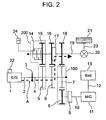
- Fig. 2 is a schematic view in the case of accelerating the vehicle in a state of running by the drive force of the engine.
- a dotted thick line in Fig. 2 shows a transmission course of the torque.
- a case of engaging the start clutch 3 and engaging the gear change dog clutch 17 with the low speed driven gear 16 is supposed.
- the torque of the engine 1 is transmitted to the transmission output shaft 19 via the low speed drive gear 6 and the low speed driven gear 16.
- the motor generator 11 since the motor generator 11 is intercepted from the transmission input shaft 4 by the motor generator dog clutch 9 and the inertia torque of the motor generator 11 can be reduced, it is not necessary to increase the torque of the engine 1 and the specific fuel consumption can be reduced at a time of acceleration.
- Figs. 3 and 4 are schematic views in the case of changing speed from the first speed drive state in Fig. 3 to the second speed drive state.
- the gear change dog clutch 17 is made in the disengaged state so as to disengage a connection between the low speed driven gear and the transmission output shaft 19 as shown in Fig. 4.
- the torque of the engine 1 is transmitted to the transmission output shaft 19 via the high speed driven gear 15 by controlling the hydraulic actuator 24 so as to press the high speed multi-plate clutch 14.
- the torque of the engine 1 is transmitted to the wheel axle 23 due to the pressing force of the high speed multi-plate clutch 14 so as to become a drive torque for the vehicle, and the rotational speed of the engine 1 is reduced due to the increased load of the engine 1 because the gear change ratio is reduced by the high speed driven gear, so that the gear change ratio between the transmission output shaft 19 and the transmission input shaft 4 becomes close to the gear change ratio of the second speed from the gear change ratio of the first speed (in the direction of becoming small).
- the torque of the engine 1 is transmitted according to a transmission course from the engine output shaft 2 to the transmission output shaft 19 successively through the start clutch 3, the transmission input shaft 4, the high speed drive gear 5, the high speed multi-plate clutch 14 and the high speed driven gear 15.
- the gear change dog clutch 17 engages with the middle speed driven gear 18 so as to engage the middle speed driven gear 18 with the transmission output shaft 19 as shown in Fig. 4.
- the hydraulic actuator 24 is controlled so as to release the pressing force of the high speed multi-plate clutch 14, whereby the gear change from the first speed to the second speed is completed.
- the torque of the engine 1 is transmitted according to a transmission course from the engine output shaft 2 to the transmission output shaft 19 successively through the start clutch 3, the transmission input shaft 4, the middle speed drive gear 6 and the middle speed driven gear 15.
- the first speed is disengaged at a time of gear change so as to become the neutral state, however, at this time, since the torque of the engine 1 is transmitted to the wheel axle 23 by the high speed multi-plate clutch 14, the high speed drive gear 5 and the high speed driven gear 15, it is not necessary that the driver returns the acceleration pedal (that is, it is not necessary that the torque and the rotational speed of the engine 1 are adjusted). According to this structure, it is possible to change speed of the gear transmission while accelerating the vehicle.
- the hydraulic actuator 24 In the case of changing the speed to the third speed, it is possible to achieve the gear change by controlling the hydraulic actuator 24 so as to make the pressing force of the high speed multi-plate clutch 14 maximum and making the gear change dog clutch 17 in a disengaged state (neutral).
- the hydraulic actuator 24 may be controlled so as to obtain a target gear change ratio in a state in Fig. 3, whereby the pressing force of the high speed multi-plate clutch 14 may be adjusted.
- the control method during the gear change mentioned above can be realized in running mode by the motor generator 11, the mode of running by the engine 1 and generating power by the motor generator 11, and running mode by the engine 1 and the motor generator 11, in addition to running mode by the engine 1 as shown in the embodiment.
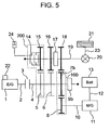
- Fig. 5 is a schematic view of a whole of an automobile system according to a second embodiment of the invention.
- This system corresponds to a structure in which a motor generator dog clutch 9 is arranged in a side of the transmission input shaft 4 and a middle speed drive gear 7b is accordingly arranged so as to freely rotate with respect to the transmission input shaft 4, in the structure shown in Fig. 1. Further, a motor generator driven gear 8b is fixed to the motor generator output shaft 10.
- the other structures are the same as those shown in Fig. 1, the same reference numerals as those in Fig. 1 are provided to the same elements in Fig. 5, and a description thereof will be omitted.
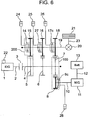
- Fig. 6 is a schematic view of a whole of an automobile system according to a third embodiment of the invention.
- This system corresponds to a structure in which a low speed multi-plate clutch 27 and a middle speed multi-plate clutch 17c are respectively arranged with respect to the low speed driven gear 16 and the middle speed driven gear 18 in place of the gear change dog clutch 17 and a motor generator multi-plate clutch 9c is arranged in place of the motor generator dog clutch 9, in the structure shown in Fig. 1. Also in this structure, it is possible to realize the same effect as the effect of engaging and disengaging the gear change dog clutch 17 and the motor generator dog clutch 9 shown in Fig. 1.
- the low speed driven gear 16 and the transmission output shaft 19 are connected so as to become in the same state as the state of setting the gear change dog clutch 17 to the 1st position in Fig. 1.
- the middle speed hydraulic actuator 26 when controlling the middle speed hydraulic actuator 26 so as to make the pressing force of the middle speed multi-plate clutch 17c maximum, the middle speed driven gear 17 and the transmission output shaft 19 are connected so as to become in the same state as the state of setting the gear change dog clutch 17 to the 2nd position in Fig. 1.
- the structure becomes in the same state as the state of setting the gear change dog clutch 17 to the N (neutral) position in Fig. 1.
- the motor generator hydraulic actuator 28 so as to adjust the pressing force of the motor generator multi-plate clutch 9c maximum, the state of turning on and off the motor generator dog clutch 9 can be realized.
- the other structures are the same as the structures shown in Fig. 1, the same reference numerals as those in Fig. 1 are attached to the same elements in Fig. 6, and a description thereof will be omitted.
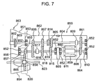
- Fig. 7 is a schematic view of a transmission for a front engine front drive vehicle (an FF vehicle) to which the present invention is applied.
- a transmission input shaft 804 and a transmission output shaft 819 are arranged in an inner portion of a housing 850 so as to be in parallel to each other and freely rotate.
- the housing 850 is constituted by a substantially cylindrical main body portion 862, a clutch housing 851 and a differential gear housing 854 which are integrally formed, a front portion 863 mounted to a front end side of the main body portion 862 and an extension portion 864 mounted to a rear end side of the main body portion 862.
- a supporting portion 865 extending to a center side from an inner peripheral surface is formed in a rear end side of the main body portion 862, a partition wall portion 853 is formed in the front portion 863, the transmission input shaft 804 extends through the partition wall portion 853, and one end portion thereof extends to a bearing 852 mounted t a rear end side of the extension portion 864, whereby the transmission input shaft 804 is rotatably supported via the partition wall portion 853 and the bearing 852.
- a start clutch 803 is mounted to an end portion protruding into the clutch housing 851 of the transmission input shaft 804, and the transmission input shaft 804 is connected to an engine output shaft 802 via the start clutch 803.
- the transmission output shaft 819 is rotatably supported to bearings 852 respectively mounted to the partition wall portion 853 and a supporting portion 865.
- a motor generator output shaft 810 is arranged on the same axis as the transmission output shaft 819.
- the motor generator shaft 810 is rotatably held by the bearings 852 respectively arranged in the supporting portion 865 and an inner surface of the extension portion 864.
- a motor generator 811 is installed within the extension portion 864, and a motor generator output shaft 810 is integrally formed with a rotor 860 thereof.
- a motor generator driven gear 808 is integrally mounted to the motor generator output shaft 810, and a motor generator drive gear 861 always engaging with the motor generator driven gear 808 is rotatably arranged on the same axis as the transmission input shaft 804.
- Reference numerals 809 denote a motor generator dog clutch, and has a function of engaging or disengaging the motor generator drive gear 861 with respect to the transmission input shaft 804.
- the differential gear housing 854 is formed in an outer side in a radial direction of the clutch housing 851 mentioned above, a differential gear carrier 858 holding a pinion 857 and a pair of right and left side gears 866 engaging with the pinion 857 are provided in an inner portion thereof, and a ring gear 856 is integrally mounted to the differential gear carrier 858. Then, a drive gar 855 engaging with the ring gear 856 is integrally mounted to the transmission output shaft 819, and a portion 820 obtained by surrounding the pinion 857, the differential gear carrier 858, the side gear 866, the ring gear 856 and the drive gear 855 is totally called as a final gear.
- reference numerals 823 denote a front wheel drive shaft, and these elements are connected to the side gear 866.
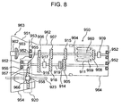
- Fig. 8 is a schematic view of a Transmission for the front engine front drive vehicle (the FF vehicle) to which the present invention is applied, in the same manner as Fig. 7, in which a method of arranging the motor generator and the high speed multi-plate clutch is changed.
- a transmission output shaft 919 extends to a rear end side of an extension portion 964 and is rotatably supported by bearings 952 respectively arranged in a main body portion 962 and an inner surface of the extension portion 964.
- a rotor 960 of the motor generator 911 corresponds to an output shaft of the motor generator and the rotor 960 is integrally formed with a motor generator driven gear 908.
- the motor generator driven gear 908 and the rotor 960 integrally formed with each other are rotatably arranged on the same axis as the transmission input shaft 904, and the structures is made such that the motor generator 911 is directly connected to the transmission input shaft 904 by engaging a motor generator dog clutch 909 with a motor generator driven gear 908. Further, a high speed driven gear 905 and a transmission output shaft 919 are connected by pressing a high speed multi-plate clutch 914. At this time, a torque from the trans-mission input shaft 904 is transmitted according to a transmission course from the transmission input shaft 904 to the transmission output shaft 919 successively through the high speed drive gear 915, the high speed driven gear 905 and the high speed multi-plate clutch 914. Since the other structures are the same as those in Fig. 8, a description thereof will be omitted.
- Fig. 9 is a schematic view showing a control device of a hybrid vehicle employing the Transmission shown in Fig. 7.
- Reference numerals 2000 in Fig. 9 denote driver's intention detecting means.
- the driver's intention detecting means normally corresponds to an acceleration pedal, a brake pedal and a shift lever.
- Reference numerals 1001 denote an engine, in the engine 1001, an amount of intake air is controlled by an electronically controlled throttle 1022 provided in an intake pipe (not shown), and an amount of fuel corresponding to the amount of air is injected from a fuel injection apparatus (not shown). Further, an ignition timing is determined from signals such as an air-fuel ratio, an engine rotational speed or the like determined by the amount of air and the amount of fuel.
- Reference numerals 2002 denote an engine control device.
- the engine control device 2002 is an apparatus for controlling the engine by the electrically controlled throttle 1022, and for example, constituted by a micro computer, an electric circuit, a motor and the like.
- An acceleration pedal opening degree, a brake pedaling force, a position of the shift lever, a residual capacity of the battery, a vehicle speed, an engine rotational speed, a motor rotational speed are input to a power train control device 2001 in Fig. 9. Further, the power train control device 2001 controls so that a torque of the engine 1001 is calculated, a throttle valve opening degree for achieving the engine torque is calculated so as to be transmitted to the engine control device 2002 by communicating means, and the electronically controlled throttle 1022 achieves a desired throttle valve opening degree.
- a torque of the motor generator 1011 is calculated so as to be transmitted to a motor control device 2005 by communicating means, whereby each of actuators is controlled.
- the motor control device 2005 charges an electric power generated by the engine 1001 and a regeneration electric power obtained at a time of reducing the speed of the vehicle into the battery, or supplies the electric power from the battery for driving the motor generator 1011, in correspondence to the volume of the battery.
- reference numerals 1003 denote a start clutch, 1014 a high speed multi-plate clutch, 1017 a gear change dog clutch and 1009 a motor generator dog clutch.
- a target start clutch position is calculated so as to be transmitted to a start clutch control device 2003 by communicating means, whereby the start clutch 1003 is controlled.
- the high speed multi-plate clutch 1014 is controlled by a multi-plate clutch control device 2005, and the gear change dog clutch 1017 and the motor generator dog clutch 1009 are controlled by a dog clutch control device 2006.
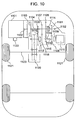
- Fig. 10 is an idiomatic view of a hybrid vehicle in which the Transmission shown in Fig. 7 is provided in a front wheel side. As shown in Fig. 10, it is possible to mount the Transmission to the automobile without adding the motor generator to the drive wheel side (for example, in a rear wheel side).
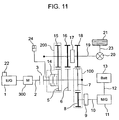
- Fig. 11 is a schematic view of a system (a fourth embodiment of the present invention) in which a motor 300 is added between the engine 1 and the start clutch 3 in the Transmission shown in Fig. 1 and the high speed multi-plate clutch is arranged in a side of the transmission input shaft.
- the motor 300 is used for starting the engine 1 and driven by the engine 1 so as to generate power. Further, when reducing speed, the start clutch 3 is set to "ON" so as to regenerate. Further, in the case that the residual capacity of the battery is sufficient, the motor 300 can be used for assisting torque, whereby a great drive force can be obtained. Further, the high speed drive gear 5 and the transmission input shaft 4 are connected by pressing the high speed multi-plate clutch 14.
- the invention is not limited to the system structure according to each of the embodiments mentioned above, and for example, the engine may be a gasoline engine or a diesel engine.
- the mechanism for transmitting the torque between the transmission input shaft and the electric rotary machine mentioned above can employ a mechanism capable of transmission torque such as a CVT, a chain, a belt or the like, in addition to the gear train.
- the clutch mechanism for engaging and disengaging between the transmission input shaft and the electric rotary machine can employ an apparatus capable of selectively transmitting and intercepting the torque, for example, a wet type multi-plate clutch, an electromagnetic clutch or the like.
- the gear change mechanism in the invention may be structured such that four stages or more for a forward movement can be set, and a gear change mechanism setting a stage for a backward movement may be provided.
Description
- The present invention relates to a structure of a power train system comprising an engine, an electric rotary machine (hereinafter, one primarily used for driving is called as an electric motor, one primarily used for generating power and starting an engine is called as a power generator and one used for driving and generating power with generally the same frequency to each other is called as a motor generator) and a gear change mechanism, and more particularly to a power transmission apparatus for improving a transmission efficiency of a power train system.
- In view of a problem of global environment, it becomes important to establish a hybrid control system for motor vehicles, in which a great reduction of specific fuel consumption can be expected.
- In JP-A-10-217779, there is disclosed an integrated hybrid power transmission apparatus constituted by a single electric rotary machine, a speed change gear mechanism and a clutch mechanism. The apparatus disclosed in the publication is so constituted that the gear change mechanism having the electric rotary machine and the clutch mechanism is integrally contained in a housing of the power transmission apparatus to make the power train system compact and light in weight. Further, by always connecting an input shaft of the gear change mechanism with the electric rotary machine, it is possible to take a driving manner so-called "a series hybrid system" in which an engine drives only the electric rotary machine to generate a power by a part of which other electric rotary machines are driven to run a vehicle. The engine and the electric rotary machine are totally controlled so as to satisfy a feeling of speed acceleration and deceleration desired by a driver and operate the engine and the electric rotary machine in a high efficiency zone.
- The system shown in JP-A-10-217779 has the following problems.
- First, in order to reduce a torque shock during changing a gear change ratio, for example, from a first speed to a second speed or from a second speed to a third speed, it is necessary to arrange the electric rotary machine in a drive wheel side to the gear change mechanism. On the contrary, in order to generate power by the engine drive force in the series hybrid manner, it is necessary to arrange the electric rotary machine in the engine side to the gear change mechanism. Accordingly, in order to prevent the gear change shock and also improve the gear change performance, at least two or more electric rotary machines are required, resulting in a problem that the drive system becomes a large size.
- Second, since a torque transfer mechanism of the engine output shaft to an electric rotary machine output shaft is complex, an efficiency of torque transmission is low.
- Third, since the drive system is so constituted that the electric rotary machine is driven by the engine, an inertia torque of the rotor of the electric rotary machine is exerted on the engine side as a load. Thus, during running under the engine drive, in order to correctly execute an acceleration command from the driver, it is necessary to generate an additional torque for cancelling the inertia torque in the engine side as well as the torque corresponding to the acceleration command. This poses a problem that the specific fuel consumption is deteriorated in order to improve a driving performance.
- DE 195 28 628 A1 discloses a transmission apparatus according to the preamble of
claim 1, for a hybrid vehicle having a clutch arranged between an engine and a gear change apparatus and an electro-motor connected via a reduction gear to the input shaft of the gear change apparatus. The input shaft and the output shaft of the gear change apparatus are synchronized by means of the electro-motor. - Accordingly, an object of the present invention is to improve a transmission efficiency, reduce a specific fuel consumption of a vehicle and make a drive system compact, in a power transmission apparatus constituted by a gear change mechanism having an electric rotary machine and a clutch mechanism, and in particular, to reduce shocks during gear changes.
- This object is achieved by a power transmission apparatus according to
claim 1. - With respect to the first problem, it is effective to dispose a mechanism of mechanically reducing a gear change shock in place of employing an electric drive force such as an electric rotary machine for reducing the gear change shock. Accordingly, the invention is of a power transmission apparatus of motor vehicles, which has an engine, a gear change apparatus arranged between the engine and a vehicle drive shaft, an electric rotary machine connected to an output shaft of the engine and the vehicle drive shaft via the gear change apparatus, and a clutch arranged between an input shaft and an output shaft of the gear change apparatus and regulating a transmission torque between the input and output shafts. According to the clutch, it is possible to reduce the gear change shock generated during the gear change operation without arranging the electric rotary machine in the drive wheel side of the gear change apparatus.
- Preferably, the power transmission apparatus of motor vehicles comprises the clutch mounted on a gear of a minimum gear change ratio in the gear change apparatus. By mounting the clutch on the gear of the minimum gear change ratio (i.e. the high speed side gear), it is possible to meet any change of rotation speed before and after the gear change operation.
- With respect to the second problem, the following technique will be possible. That is, in the hybrid vehicle, in order to improve the specific fuel consumption of the engine, there may be a case of stopping the engine when stopping the vehicle and using the electric rotary machine for starting the engine at every time of starting the vehicle. In this case, in view of an electric efficiency, it is effective to reduce and transmit the rotation of the electric rotary machine to the engine shaft via the gear change apparatus in place of directly transmitting the rotation to the engine shaft. Thus, there may be provided a power transmission apparatus of motor vehicles having an engine, a gear change apparatus arranged between the engine and a vehicle drive shaft, and an electric rotary machine connected to an output shaft of the engine and the vehicle drive shaft via the gear change apparatus, wherein a rotation of an output shaft of the electric rotary machine is reduced and transmitted to an engine side input shaft of the gear change apparatus.
- Further, in the case of driving the electric rotary machine by an engine power to generate electric power, it is effective to restrict the number of transmission mechanisms for transmitting the engine power to the electric rotary machine (e.g. the number of gears) to be small. Thus, there may be provided a power transmission apparatus of motor vehicles having an engine, a gear change apparatus arranged between the engine and a vehicle drive shaft, and an electric rotary machine connected to an output shaft of the engine and the vehicle drive shaft via the gear change apparatus, wherein the output shafts of the engine and the electric rotary machine are provided separately, and gears respectively mounted on the both shafts for transmitting the power on the both shafts directly engage with one another. By the direct engagement of the gears without interposing another gear there between, it is possible to restrain a reduction of the efficiency of power transmission.
- More preferably, a power transmission apparatus of motor vehicles may further have a clutch for breaking the connection between the output shaft of the electric rotary machine and the input shaft of the gear change apparatus at the electric rotary machine side. According to the clutch, it is possible to optionally break the connection of the engine and the electric rotary machine and prevent the inertia torque of the electric rotary machine from being exerted on the engine side as a load, thereby the third problem mentioned above can be solved.
- A description will be given in detail below of an embodiment according to the invention referring to the accompanying drawings.
-
- Fig. 1 is a schematic view of a drive system of motor vehicles according to a first embodiment of the invention;
- Fig. 2 is the driving system shown in Fig. 1, which shows a torque transmission course when running by an engine driving force;
- Fig. 3 is the driving system shown in Fig. 1, which shows a torque transmission course during a gear change operation;
- Fig. 4 is the driving system shown in Fig. 1, which shows a torque transmission course after the gear change operation;
- Fig. 5 is a schematic view of a drive system of a motor vehicle according to a second embodiment of the invention;
- Fig. 6 is a schematic view of a drive system of a motor vehicle according to a third embodiment of the invention;
- Fig. 7 is a schematic view of a transmission of a front engine front drive vehicle (FF vehicles) to which the invention is applied;
- Fig. 8 is a schematic view of another transmission of the FF vehicles to which the invention is applied;
- Fig. 9 is a schematic view showing a control system of a hybrid motor vehicle to which the invention is applied;
- Fig. 10 is a schematic view of a hybrid motor vehicle in which a transmission according to the invention is provided in a front wheel side; and
- Fig. 11 is a schematic view of a drive system of motor vehicles according to a fourth embodiment of the invention.
-
- Fig. 1 is a schematic view showing a whole drive system of motor vehicles according to a first embodiment of the invention.
Reference numeral 1 denotes an engine and 11 a motor generator which outputs a kinetic energy by an electric energy provided from abattery 13 and which converts an applied kinetic energy into an electric energy to store into thebattery 13.Reference numerals 21 denote a wheel and 23 a wheel axle. -
Reference numeral 5 denotes a gear generally called as a high speed drive gear, and 15 a gear generally called as a high speed driven gear which engages with the highspeed drive gear 5. The highspeed drive gear 5 is fixed on atransmission input shaft 4. -
Reference numeral 6 denotes a gear generally called as a low speed drive gear, and 16 a gear generally called as a low speed driven gear which engages with the lowspeed drive gear 6. The lowspeed drive gear 6 is fixed on thetransmission input shaft 4. -
Reference numeral 7 denotes a gear generally called as a middle speed drive gear which is fixed on thetransmission input shaft 5.Reference numerals 18 denote a gear generally called as a middle speed driven gear, and 8 a motor generator driven gear. The middle speed drivengear 18 and the motor generator drivengear 8 engage with the middlespeed drive gear 7, respectively. The relationship between the middlespeed drive gear 7 and the motor generator drivengear 8 is set so as to have a gear ratio of transmitting a torque from the motorgenerator output shaft 10 to thetransmission input shaft 4 with a reduced speed. -
Reference numeral 9 denotes a motor generator dog clutch which has a function of engaging or disengaging the motorgenerator output shaft 10 with or from the motor generator drivengear 8.Reference numerals 17 denote a gear change dog clutch. The gearchange dog clutch 17 has a function of engaging or disengaging thetransmission output shaft 19 with or from the low speed drivengear 16 or the middle speed drivengear 18. - In general, it has been known that the dog clutch is free from slip loss when engaged and has a high transmission efficiency. Further, the torque transfer mechanism is of the middle
speed drive gear 7 and the motor generator drivengear 8 as shown by adotted line 100. -
Reference numeral 3 denotes a start clutch. It may be a so-called dry type in which a clutch disc mounted to thetransmission input shaft 4 is pinched between a flywheel and a pressure plate to transmit a torque, and which may have a mechanism for performing an "ON/OFF" operation is of such a type that an operation force of a clutch pedal (not shown) is transmitted by a hydraulic actuator or the like. Thestart clutch 3 may be also those conventionally known, such as a wet type multi-plate clutch, an electromagnetic clutch and so on. -
Reference numerals 14 denote a high speed multi-plate clutch which has a function of engaging and disengaging with and from the high speed drivengear 15 under an operation of ahydraulic actuator 24. Here, when the highspeed multi-plate clutch 14 is gradually pressed by thehydraulic actuator 24, the torque of thetransmission input shaft 4 is gradually transmitted to thetransmission output shaft 19. A rotational speed of thetransmission output shaft 19 can be controlled with relation to a load (a road status, a weight of vehicle body, etc.) by controlling a force for pressing the highspeed multi-plate clutch 14 by means of thehydraulic actuator 24. In this case, a torque of theengine 1 is transmitted along a transmission course from theengine output shaft 2 to thetransmission output shaft 19 successively through thestart clutch 3, thetransmission input shaft 4, the highspeed drive gear 5, the highspeed multi-plate clutch 14 and the high speed driven gear 15 (see Fig. 3). - Next, referring to Table 1, a description will be given of a basic processing method for controlling the
engine 1 and themotor generator 11 in respective operating modes. Here, with respect to the gearchange dog clutch 17, a state that it engages with the low speed drivengear 16 is defined as a 1st position, a state that it engages with the middle speed drivengear 18 is defined as a 2nd position, and an "OFF" state thereof is defined as an N (neutral) position.
- First, a description will be given of a control method in the stop mode. At a time of idling power generation (No. 1 in Table 1), the
start clutch 3 is set to "ON", the highspeed multi-plate clutch 14 is set to "OFF", the gearchange dog clutch 17 is set to the N (neutral) position, and the motorgenerator dog clutch 9 is set to "ON". Accordingly, the torque from theengine 1 is transmitted to themotor generator 11 via the middlespeed drive gear 7 and the motor generator drivengear 8, and it is possible to generate power while idling theengine 1 in a state that the vehicle stops. Further, in order to realize a smooth start from this state, it is necessary to start the vehicle while slipping the highspeed multi-plate clutch 14. After starting, the highspeed multi-plate clutch 14 is quickly disengaged, thetransmission input shaft 4 and thetransmission output shaft 19 are synchronously rotated by using themotor generator 11, an electronically controlledthrottle 22 and the like, and the gearchange dog clutch 17 is set to the 1st position. At this time, in the case that the gear change ratio of a gear stage having the multi-plate clutch arranged is small, there is a risk that the engine stops without starting. In this case, the engine is prevented from stopping at a time of starting by increasing the torque of themotor generator 11. Further, as another starting method, there is a method of first setting thestart clutch 3 to "OFF", thereafter controlling themotor generator 11 so as to synchronously rotate thetransmission input shaft 4 and thetransmission output shaft 19, engaging the gearchange dog clutch 17 with the 1st position, and starting to the torque of theengine 1 while slipping thestart clutch 3 as conventionally known or starting by themotor generator 11. - Next, a description will be given of a control method at a time of idling stop (No. 2). The idling stop can be performed by setting the start clutch to "OFF" from the state of the idling power generation (No. 1) and stopping a fuel supply to the
engine 1. At this time, it is necessary to set the gearchange dog clutch 17 to the 1st position for realizing a smooth start from the idling stop. When starting, it is possible to employ a method of starting according to the torque of themotor generator 11 and a method of starting according to the torque of themotor generator 11 and push-starting theengine 1. In the case of push-starting theengine 1, it is necessary to control the rotational speed of theengine 1 within a range capable of starting while slipping thestart clutch 3. Further, in the case of push-start, it is significantly effective to utilize an engine with electromagnetic drive type intake and exhaust valves. In the conventional type of engine in which the intake and exhaust valves are opened and closed by rotating a cam shaft, there is a cylinder at which the intake and exhaust valves are closed when the engine stops and this generates a great load, so that it is necessary that themotor generator 11 generates a great torque when push-starting. On the contrary, in the engine with the electromagnetic drive type intake and exhaust valves, it is possible to open the valves in all the cylinders when the engine stops and the load is reduced, so that the push-start can be easily performed, it is not necessary that themotor generator 11 outputs a great torque, whereby it is possible to make themotor generator 11 compact. Further, the structure may be made such as to start by the torque of themotor generator 11 according to a conventionally known starter motor (adotted line 300 in Fig. 1) disposed in the engine side and startengine 1 by the starter motor so as to gradually engage the start clutch and add the torque of theengine 1, thereby running. - Next, a description will be given of a travel by the
motor generator 11. When reversing (No. 3), thestart clutch 3 is set to "OFF", the motorgenerator dog clutch 9 is set to "ON", and any one of the low speed drivengear 16, the middle speed drivengear 18 and the high speed drivengear 15 is selected so as to rotate themotor generator 11 in a negative direction (a forward direction of the vehicle is set to a positive direction and a backward direction is set to a negative direction), thereby running. It has been known that a great drive torque is required when reversing, the gearchange dog clutch 17 may be set to the 1st position and the highspeed multi-plate clutch 14 may be set to "OFF". Further, at a time of backward moving, the vehicle may be backwardly moved by engaging with a reverse gear (not shown) and transmitting the torque of theengine 1 to awheel 21 while slipping thestart clutch 3 as conventionally known. At a time of low vehicle speed (No. 4), thestart clutch 3 is set to "OFF", the gearchange dog clutch 17 is set to the 1st position, the motorgenerator dog clutch 9 is set to "ON", the highspeed multi-plate clutch 14 is set to "OFF", and themotor generator 11 is positively rotated, thereby running the vehicle. In the same manner, at a time of middle vehicle speed (No. 5), thestart clutch 3 is set to "OFF", the gearchange dog clutch 17 is set to the 2nd position, the motorgenerator dog clutch 9 is set to "ON", and the highspeed multi-plate clutch 14 is set to "OFF". Further, at a time of high vehicle speed (No. 6), thestart clutch 3 is set to "OFF", the gearchange dog clutch 17 is set to the N (neutral) position, the motorgenerator dog clutch 9 is set to "ON", and the highspeed multi-plate clutch 14 is set to "ON". Further, in the drive modes Nos. 3 to 6 mentioned above, since themotor generator 11 is directly connected to thetransmission output shaft 19, the energy can be regenerated at a time of reducing the speed. Further, in the drive modes Nos. 4 to 6 mentioned above, it is possible to control thestart clutch 3 so as to push-start theengine 1. Further, as mentioned above, it is possible to start theengine 1 by the starter motor and control thestart clutch 3, thereby running according to the torque of theengine 1. - Next, a description will be given of a travel by the
engine 1 at a time of low vehicle speed (in a first speed drive state). Thestart clutch 3 is set to "ON", the highspeed multi-plate clutch 14 is set to "OFF", the gearchange dog clutch 17 is set to the 1st position, and the motorgenerator dog clutch 9 is set to "OFF" (No. 7). At this time, it is possible to run at a low vehicle speed by theengine 1. Further, thestart clutch 3 is set to "ON", the highspeed multi-plate clutch 14 is set to "OFF", the gear change dog clutch is set to the 1st position, and the motorgenerator dog clutch 9 is set to "ON" (No. 8). At this time, in the case that a residual capacity of thebattery 13 is a little and a necessity of generating power by driving themotor generator 11 by means of theengine 1 is generated, running by theengine 1 and the power generation by themotor generator 11 can be performed. Further, in the case that thebattery 13 is fully charged and has the residual capacity in reserve, a torque assist can be performed by themotor generator 11, and running can be performed by theengine 1 and themotor generator 11. Further, in the drive motor No. 8 mentioned above, since themotor generator 11 is directly connected to thetransmission output shaft 19, energy can be regenerated when reducing the speed. - Next, a description will be given of running by the
engine 1 at the middle vehicle speed time (in the second speed drive state). - The
start clutch 3 is set to "ON", the highspeed multi-plate clutch 14 is set to "OFF", the gearchange dog clutch 17 is set to the 2nd position, and the motorgenerator dog clutch 9 is set to "OFF" (No. 9). At this time, it is possible to run at middle vehicle speed by theengine 1. Further, thestart clutch 3 is set to "ON", the highspeed multi-plate clutch 14 is set to "OFF", the gear change dog clutch is set to the 2nd position, and the motorgenerator dog clutch 9 is set to "ON" (No. 10). In the same manner as that at the low vehicle speed time, in the case that a residual capacity of thebattery 13 is a little and a necessity of generating power by driving themotor generator 11 by means of theengine 1 is generated, running by theengine 1 and the power generation by themotor generator 11 can be performed. Further, in the case that thebattery 13 is fully charged and has the residual capacity in reserve, a torque assist can be performed by themotor generator 11, and running can be performed by theengine 1 and themotor generator 11. Further, in the drive motor No. 10 mentioned above, since themotor generator 11 is directly connected to thetransmission output shaft 19, an energy can be regenerated when reducing the speed. - Next, a description will be given of running by the
engine 1 at the high vehicle speed time (in the third speed drive state). - The
start clutch 3 is set to "ON", the highspeed multi-plate clutch 14 is set to "OFF", the gearchange dog clutch 17 is set to the N (neutral) position, and the motorgenerator dog clutch 9 is set to "OFF" (No. 11). At this time, it is possible to run at high vehicle speed by theengine 1. Further, thestart clutch 3 is set to "ON", the highspeed multi-plate clutch 14 is set to "OFF", the gear change dog clutch is set to the N (neutral) position, and the motorgenerator dog clutch 9 is set to "ON" (No. 12). In the same manner as that at the low and middle vehicle speed times, in the case that a residual capacity of thebattery 13 is a little and a necessity of generating power by driving themotor generator 11 by means of theengine 1 is generated, running by theengine 1 and the power generation by themotor generator 11 can be performed. Further, in the case that thebattery 13 is fully charged and has the residual capacity in reserve, a torque assist can be performed by themotor generator 11, and running can be performed by theengine 1 and themotor generator 11. Further, in the drive motor No. 10 mentioned above, since themotor generator 11 is directly connected to thetransmission output shaft 19, an energy can be regenerated when reducing the speed. - Further, at a time of running by the
engine 1 mentioned above, in the case that the power generation and the torque assist by themotor generator 11, it is necessary to control themotor generator 11 so as to synchronously rotate the motorgenerator output shaft 10 and thetransmission input shaft 4. - Further, in the structure according to the invention, it is possible to regenerate the energy at the speed reduction time in all the drive modes during running. For example, in the drive modes No. 7, 9 and 11 mentioned above, when synchronizing the
transmission input shaft 4 and the motorgenerator output shaft 10 and setting the motorgenerator dog clutch 9 to "ON" at the speed reduction time, the energy can be regenerated. - Further, since the
motor generator 11 serves as a starter for starting theengine 1, a gear ratio between the middlespeed drive gear 7 and the motor generator drivengear 8 is designed so as to transmit the torque from thetransmission input shaft 4 to themotor generator 11 in an increasing manner. Accordingly, since it is possible to reduce the torque of themotor generator 11 required at a time of starting theengine 1 and the torque of themotor generator 11 is transmitted to thetransmission input shaft 4 in a reducing manner, it is possible to reduce the torque of themotor generator 11 required when running and assisting torque by themotor generator 11, so that it is possible to make themotor generator 11 compact and light. - Further, in the conventional embodiment, two pairs of gear trains are provided in a transmission course between the engine and the motor generator, however, in the embodiment according to the present invention, the gear trains are reduced to one pair. Accordingly, a transmission efficiency when generating power by the
engine 1 can be improved and the specific fuel consumption can be further reduced. - Fig. 2 is a schematic view in the case of accelerating the vehicle in a state of running by the drive force of the engine. A dotted thick line in Fig. 2 shows a transmission course of the torque. As an example, a case of engaging the
start clutch 3 and engaging the gearchange dog clutch 17 with the low speed drivengear 16 is supposed. At this time, the torque of theengine 1 is transmitted to thetransmission output shaft 19 via the lowspeed drive gear 6 and the low speed drivengear 16. Here, in the case of accelerating the vehicle, since themotor generator 11 is intercepted from thetransmission input shaft 4 by the motorgenerator dog clutch 9 and the inertia torque of themotor generator 11 can be reduced, it is not necessary to increase the torque of theengine 1 and the specific fuel consumption can be reduced at a time of acceleration. - Figs. 3 and 4 are schematic views in the case of changing speed from the first speed drive state in Fig. 3 to the second speed drive state. When the vehicle speed becomes in the gear change state, the gear
change dog clutch 17 is made in the disengaged state so as to disengage a connection between the low speed driven gear and thetransmission output shaft 19 as shown in Fig. 4. At the same time, the torque of theengine 1 is transmitted to thetransmission output shaft 19 via the high speed drivengear 15 by controlling thehydraulic actuator 24 so as to press the highspeed multi-plate clutch 14. The torque of theengine 1 is transmitted to thewheel axle 23 due to the pressing force of the highspeed multi-plate clutch 14 so as to become a drive torque for the vehicle, and the rotational speed of theengine 1 is reduced due to the increased load of theengine 1 because the gear change ratio is reduced by the high speed driven gear, so that the gear change ratio between thetransmission output shaft 19 and thetransmission input shaft 4 becomes close to the gear change ratio of the second speed from the gear change ratio of the first speed (in the direction of becoming small). At this time, the torque of theengine 1 is transmitted according to a transmission course from theengine output shaft 2 to thetransmission output shaft 19 successively through thestart clutch 3, thetransmission input shaft 4, the highspeed drive gear 5, the highspeed multi-plate clutch 14 and the high speed drivengear 15. Here, when the gear change ratio between thetransmission input shaft 4 and thetransmission output shaft 19 becomes the gear change ratio of the second speed, the gearchange dog clutch 17 engages with the middle speed drivengear 18 so as to engage the middle speed drivengear 18 with thetransmission output shaft 19 as shown in Fig. 4. When the connection is completed, thehydraulic actuator 24 is controlled so as to release the pressing force of the highspeed multi-plate clutch 14, whereby the gear change from the first speed to the second speed is completed. At this time, the torque of theengine 1 is transmitted according to a transmission course from theengine output shaft 2 to thetransmission output shaft 19 successively through thestart clutch 3, thetransmission input shaft 4, the middlespeed drive gear 6 and the middle speed drivengear 15. - As mentioned above, the first speed is disengaged at a time of gear change so as to become the neutral state, however, at this time, since the torque of the
engine 1 is transmitted to thewheel axle 23 by the highspeed multi-plate clutch 14, the highspeed drive gear 5 and the high speed drivengear 15, it is not necessary that the driver returns the acceleration pedal (that is, it is not necessary that the torque and the rotational speed of theengine 1 are adjusted). According to this structure, it is possible to change speed of the gear transmission while accelerating the vehicle. On the contrary, in the case that the driver returns the acceleration pedal and controls the electronically controlledthrottle 22 so as to narrow the throttle during the driving, a rotational synchronization between thetransmission input shaft 4 and thetransmission output shaft 19 by the highspeed multi-plate clutch 14 becomes early (the rotational speed of theengine 1 is early reduced), so that it is possible to shorten a time for changing the speed. - In the case of changing the speed to the third speed, it is possible to achieve the gear change by controlling the
hydraulic actuator 24 so as to make the pressing force of the highspeed multi-plate clutch 14 maximum and making the gearchange dog clutch 17 in a disengaged state (neutral). Here, in the case of increasing the gear change ratio (shift down), thehydraulic actuator 24 may be controlled so as to obtain a target gear change ratio in a state in Fig. 3, whereby the pressing force of the highspeed multi-plate clutch 14 may be adjusted. Further, the control method during the gear change mentioned above can be realized in running mode by themotor generator 11, the mode of running by theengine 1 and generating power by themotor generator 11, and running mode by theengine 1 and themotor generator 11, in addition to running mode by theengine 1 as shown in the embodiment. - Fig. 5 is a schematic view of a whole of an automobile system according to a second embodiment of the invention. This system corresponds to a structure in which a motor
generator dog clutch 9 is arranged in a side of thetransmission input shaft 4 and a middlespeed drive gear 7b is accordingly arranged so as to freely rotate with respect to thetransmission input shaft 4, in the structure shown in Fig. 1. Further, a motor generator driven gear 8b is fixed to the motorgenerator output shaft 10. The other structures are the same as those shown in Fig. 1, the same reference numerals as those in Fig. 1 are provided to the same elements in Fig. 5, and a description thereof will be omitted. Further, when employing the structure, there is a disadvantage that themotor generator 11 is rotated in an accompanying manner when running according to theengine 1 in the drive mode No. 9 shown in Table 1, however, it is possible to disengage themotor generator 11 when running according to theengine 1 in the other drive modes, and since the inertia torque of themotor generator 11 can be reduced in the case of accelerating the vehicle, it is not necessary to increase the torque of theengine 1, whereby the specific fuel consumption can be reduced when accelerating. - Fig. 6 is a schematic view of a whole of an automobile system according to a third embodiment of the invention. This system corresponds to a structure in which a low
speed multi-plate clutch 27 and a middle speed multi-plate clutch 17c are respectively arranged with respect to the low speed drivengear 16 and the middle speed drivengear 18 in place of the gearchange dog clutch 17 and a motorgenerator multi-plate clutch 9c is arranged in place of the motorgenerator dog clutch 9, in the structure shown in Fig. 1. Also in this structure, it is possible to realize the same effect as the effect of engaging and disengaging the gearchange dog clutch 17 and the motorgenerator dog clutch 9 shown in Fig. 1. For example, when controlling the low speedhydraulic actuator 25 so as to make the pressing force of the lowspeed multi-plate clutch 27 maximum, the low speed drivengear 16 and thetransmission output shaft 19 are connected so as to become in the same state as the state of setting the gearchange dog clutch 17 to the 1st position in Fig. 1. In the same manner, when controlling the middle speedhydraulic actuator 26 so as to make the pressing force of the middle speed multi-plate clutch 17c maximum, the middle speed drivengear 17 and thetransmission output shaft 19 are connected so as to become in the same state as the state of setting the gearchange dog clutch 17 to the 2nd position in Fig. 1. - Further, when controlling the low speed
hydraulic actuator 25 and the middle speedhydraulic actuator 26 so as to release the pressing force of the lowspeed multi-plate clutch 27 and the middle speed multi-plate clutch 17c, the structure becomes in the same state as the state of setting the gearchange dog clutch 17 to the N (neutral) position in Fig. 1. In the same manner, when controlling the motor generatorhydraulic actuator 28 so as to adjust the pressing force of the motorgenerator multi-plate clutch 9c maximum, the state of turning on and off the motorgenerator dog clutch 9 can be realized. The other structures are the same as the structures shown in Fig. 1, the same reference numerals as those in Fig. 1 are attached to the same elements in Fig. 6, and a description thereof will be omitted. - Fig. 7 is a schematic view of a transmission for a front engine front drive vehicle (an FF vehicle) to which the present invention is applied. A
transmission input shaft 804 and atransmission output shaft 819 are arranged in an inner portion of ahousing 850 so as to be in parallel to each other and freely rotate. Thehousing 850 is constituted by a substantially cylindricalmain body portion 862, aclutch housing 851 and adifferential gear housing 854 which are integrally formed, afront portion 863 mounted to a front end side of themain body portion 862 and anextension portion 864 mounted to a rear end side of themain body portion 862. A supportingportion 865 extending to a center side from an inner peripheral surface is formed in a rear end side of themain body portion 862, apartition wall portion 853 is formed in thefront portion 863, thetransmission input shaft 804 extends through thepartition wall portion 853, and one end portion thereof extends to abearing 852 mounted t a rear end side of theextension portion 864, whereby thetransmission input shaft 804 is rotatably supported via thepartition wall portion 853 and thebearing 852. Astart clutch 803 is mounted to an end portion protruding into theclutch housing 851 of thetransmission input shaft 804, and thetransmission input shaft 804 is connected to anengine output shaft 802 via thestart clutch 803. On the contrary, thetransmission output shaft 819 is rotatably supported tobearings 852 respectively mounted to thepartition wall portion 853 and a supportingportion 865. Further, a motorgenerator output shaft 810 is arranged on the same axis as thetransmission output shaft 819. Themotor generator shaft 810 is rotatably held by thebearings 852 respectively arranged in the supportingportion 865 and an inner surface of theextension portion 864. Amotor generator 811 is installed within theextension portion 864, and a motorgenerator output shaft 810 is integrally formed with arotor 860 thereof. - Further, a motor generator driven
gear 808 is integrally mounted to the motorgenerator output shaft 810, and a motorgenerator drive gear 861 always engaging with the motor generator drivengear 808 is rotatably arranged on the same axis as thetransmission input shaft 804.Reference numerals 809 denote a motor generator dog clutch, and has a function of engaging or disengaging the motorgenerator drive gear 861 with respect to thetransmission input shaft 804. Thedifferential gear housing 854 is formed in an outer side in a radial direction of theclutch housing 851 mentioned above, adifferential gear carrier 858 holding apinion 857 and a pair of right and left side gears 866 engaging with thepinion 857 are provided in an inner portion thereof, and aring gear 856 is integrally mounted to thedifferential gear carrier 858. Then, adrive gar 855 engaging with thering gear 856 is integrally mounted to thetransmission output shaft 819, and aportion 820 obtained by surrounding thepinion 857, thedifferential gear carrier 858, theside gear 866, thering gear 856 and thedrive gear 855 is totally called as a final gear. In this case,reference numerals 823 denote a front wheel drive shaft, and these elements are connected to theside gear 866. - Fig. 8 is a schematic view of a Transmission for the front engine front drive vehicle (the FF vehicle) to which the present invention is applied, in the same manner as Fig. 7, in which a method of arranging the motor generator and the high speed multi-plate clutch is changed. In Fig. 8, a
transmission output shaft 919 extends to a rear end side of anextension portion 964 and is rotatably supported bybearings 952 respectively arranged in amain body portion 962 and an inner surface of theextension portion 964. Further, arotor 960 of themotor generator 911 corresponds to an output shaft of the motor generator and therotor 960 is integrally formed with a motor generator drivengear 908. The motor generator drivengear 908 and therotor 960 integrally formed with each other are rotatably arranged on the same axis as thetransmission input shaft 904, and the structures is made such that themotor generator 911 is directly connected to thetransmission input shaft 904 by engaging a motorgenerator dog clutch 909 with a motor generator drivengear 908. Further, a high speed drivengear 905 and atransmission output shaft 919 are connected by pressing a highspeed multi-plate clutch 914. At this time, a torque from the trans-mission input shaft 904 is transmitted according to a transmission course from thetransmission input shaft 904 to thetransmission output shaft 919 successively through the highspeed drive gear 915, the high speed drivengear 905 and the highspeed multi-plate clutch 914. Since the other structures are the same as those in Fig. 8, a description thereof will be omitted. - Fig. 9 is a schematic view showing a control device of a hybrid vehicle employing the Transmission shown in Fig. 7.
Reference numerals 2000 in Fig. 9 denote driver's intention detecting means. The driver's intention detecting means normally corresponds to an acceleration pedal, a brake pedal and a shift lever.Reference numerals 1001 denote an engine, in theengine 1001, an amount of intake air is controlled by an electronically controlledthrottle 1022 provided in an intake pipe (not shown), and an amount of fuel corresponding to the amount of air is injected from a fuel injection apparatus (not shown). Further, an ignition timing is determined from signals such as an air-fuel ratio, an engine rotational speed or the like determined by the amount of air and the amount of fuel.Reference numerals 2002 denote an engine control device. Theengine control device 2002 is an apparatus for controlling the engine by the electrically controlledthrottle 1022, and for example, constituted by a micro computer, an electric circuit, a motor and the like. An acceleration pedal opening degree, a brake pedaling force, a position of the shift lever, a residual capacity of the battery, a vehicle speed, an engine rotational speed, a motor rotational speed are input to a powertrain control device 2001 in Fig. 9. Further, the powertrain control device 2001 controls so that a torque of theengine 1001 is calculated, a throttle valve opening degree for achieving the engine torque is calculated so as to be transmitted to theengine control device 2002 by communicating means, and the electronically controlledthrottle 1022 achieves a desired throttle valve opening degree. - Further, in the power
train control device 2001, a torque of the motor generator 1011 is calculated so as to be transmitted to amotor control device 2005 by communicating means, whereby each of actuators is controlled. Themotor control device 2005 charges an electric power generated by theengine 1001 and a regeneration electric power obtained at a time of reducing the speed of the vehicle into the battery, or supplies the electric power from the battery for driving the motor generator 1011, in correspondence to the volume of the battery. Further, in Fig. 9,reference numerals 1003 denote a start clutch, 1014 a high speed multi-plate clutch, 1017 a gear change dog clutch and 1009 a motor generator dog clutch. In the powertrain control device 2001, a target start clutch position is calculated so as to be transmitted to a startclutch control device 2003 by communicating means, whereby the start clutch 1003 is controlled. In the same manner, the highspeed multi-plate clutch 1014 is controlled by a multi-plateclutch control device 2005, and the gearchange dog clutch 1017 and the motorgenerator dog clutch 1009 are controlled by a dogclutch control device 2006. - Fig. 10 is an idiomatic view of a hybrid vehicle in which the Transmission shown in Fig. 7 is provided in a front wheel side. As shown in Fig. 10, it is possible to mount the Transmission to the automobile without adding the motor generator to the drive wheel side (for example, in a rear wheel side).
- Fig. 11 is a schematic view of a system (a fourth embodiment of the present invention) in which a
motor 300 is added between theengine 1 and thestart clutch 3 in the Transmission shown in Fig. 1 and the high speed multi-plate clutch is arranged in a side of the transmission input shaft. Themotor 300 is used for starting theengine 1 and driven by theengine 1 so as to generate power. Further, when reducing speed, thestart clutch 3 is set to "ON" so as to regenerate. Further, in the case that the residual capacity of the battery is sufficient, themotor 300 can be used for assisting torque, whereby a great drive force can be obtained. Further, the highspeed drive gear 5 and thetransmission input shaft 4 are connected by pressing the highspeed multi-plate clutch 14. At this time, a torque from thetransmission input shaft 4 is transmitted according to a transmission course from thetransmission input shaft 4 to thetransmission output shaft 19 successively through the highspeed multi-plate clutch 14, the highspeed drive gear 5 and the high speed drivengear 15. The other structures are the same as the structures shown in Fig. 1, the same reference numerals in Fig. 1 are attached to the same elements in Fig. 11, and a description thereof will be omitted. - In this case, the invention is not limited to the system structure according to each of the embodiments mentioned above, and for example, the engine may be a gasoline engine or a diesel engine. Further, the mechanism for transmitting the torque between the transmission input shaft and the electric rotary machine mentioned above can employ a mechanism capable of transmission torque such as a CVT, a chain, a belt or the like, in addition to the gear train. The clutch mechanism for engaging and disengaging between the transmission input shaft and the electric rotary machine can employ an apparatus capable of selectively transmitting and intercepting the torque, for example, a wet type multi-plate clutch, an electromagnetic clutch or the like. Further, the gear change mechanism in the invention may be structured such that four stages or more for a forward movement can be set, and a gear change mechanism setting a stage for a backward movement may be provided.
- As will be apparent from the above, according to the invention, the following technical advantages can be obtained:
- (1) According to the clutch for adjusting the transmission torque between the input shaft and the output shaft in the gear change apparatus, it is possible to reduce the gear change shock generated during the gear change operation without adding the electric rotary machine to the drive wheel side from the gear change apparatus.
- (2) According to the feature that the rotation of the output shaft in the electric rotary machine is reduced so as to be transmitted to the engine side input shaft in a reduced manner, an electric efficiency when restarting the engine is improved.
- (3) According to the feature of engaging the gears provided in the output shaft of the engine and the output shaft of the electric rotary machine with each other without interposing the other gears therebetween, it is possible to restrict an efficiency reduction at a time of engine power generation.
- (4) According to the clutch for disengaging the output shaft of the electric rotary machine from the electric rotary machine side input shaft of the gear change apparatus, it is possible to disengage the engine from the electric rotary machine as occasion demands and prevent the inertia torque of the electric rotary machine from applying to the engine side as a load.
-
Claims (5)
- A power transmission apparatus of motor vehicles comprising:characterized byan engine (1);a gear change apparatus provided between said engine (1) and a vehicle drive shaft (23); andan electric rotary machine (11) connected to an output shaft (2) of said engine (1) and said vehicle drive shaft (23) via said gear change apparatus;
a clutch (14) provided between an input shaft (4) and an output shaft (19) of said gear change apparatus, for adjusting a transmission torque between said input shaft (4) and said output shaft (19). - A power transmission apparatus of motor vehicles according to claim 1, wherein said clutch (14) is mounted on a gear having a minimum gear change ratio in said gear change apparatus.
- A power transmission apparatus of motor vehicles according to claim 1 or 2, further having a clutch (9) for intercepting the output shaft (10) of said electric rotary machine (11) from the electric rotary machine side input shaft of said gear change apparatus.
- A power transmission apparatus of motor vehicles according to any of claims 1 to 3,
wherein a rotation of an output shaft (10) of said electric rotary machine (11) is reduced and transmitted to an engine side input shaft (4) of said gear change apparatus. - A power transmission apparatus of motor vehicles according to any of claims 1 to 4,
wherein the output shafts of said engine (1) and said electric rotary machine (11) are provided separately, and
gears respectively mounted on said two shafts for transmitting the power of the output shaft (2) of said engine (1) and the output shaft (10) of said electric rotary machine (11) directly engage with each other.
Applications Claiming Priority (2)
| Application Number | Priority Date | Filing Date | Title |
|---|---|---|---|
| JP2000032799 | 2000-02-04 | ||
| JP2000032799 | 2000-02-04 |
Publications (3)
| Publication Number | Publication Date |
|---|---|
| EP1122111A2 EP1122111A2 (en) | 2001-08-08 |
| EP1122111A3 EP1122111A3 (en) | 2003-01-29 |
| EP1122111B1 true EP1122111B1 (en) | 2005-07-06 |
Family
ID=18557353
Family Applications (2)
| Application Number | Title | Priority Date | Filing Date |
|---|---|---|---|
| EP00118265A Expired - Lifetime EP1122111B1 (en) | 2000-02-04 | 2000-09-04 | A power transmission apparatus for hybrid vehicles |
| EP01102179A Withdrawn EP1122110A3 (en) | 2000-02-04 | 2001-02-02 | A power transmission apparatus of motor vehicles |
Family Applications After (1)
| Application Number | Title | Priority Date | Filing Date |
|---|---|---|---|
| EP01102179A Withdrawn EP1122110A3 (en) | 2000-02-04 | 2001-02-02 | A power transmission apparatus of motor vehicles |
Country Status (4)
| Country | Link |
|---|---|
| US (2) | US7185722B1 (en) |
| EP (2) | EP1122111B1 (en) |
| KR (2) | KR20010077862A (en) |
| DE (1) | DE60021163T2 (en) |
Cited By (1)
| Publication number | Priority date | Publication date | Assignee | Title |
|---|---|---|---|---|
| CN103277504A (en) * | 2013-06-04 | 2013-09-04 | 潍柴动力股份有限公司 | Control method for gear selecting and shifting of automatic gearbox and vehicle applying control method |
Families Citing this family (80)
| Publication number | Priority date | Publication date | Assignee | Title |
|---|---|---|---|---|
| JP3668830B2 (en) * | 1998-08-28 | 2005-07-06 | トヨタ自動車株式会社 | Power transmission device and hybrid vehicle using the same |
| DE19953495C2 (en) * | 1999-11-06 | 2002-10-24 | Daimler Chrysler Ag | Drive unit for a motor vehicle |
| DE10052231A1 (en) * | 2000-10-21 | 2002-05-02 | Daimler Chrysler Ag | vehicle |
| DE10058020B4 (en) * | 2000-11-23 | 2013-09-12 | Burani Consulting Limited Liability Company | Automotive drive |
| JP3810654B2 (en) * | 2001-06-11 | 2006-08-16 | 本田技研工業株式会社 | Control device for hybrid vehicle |
| JP4114529B2 (en) * | 2002-07-04 | 2008-07-09 | 国産電機株式会社 | Internal combustion engine drive vehicle and power transmission device intermittent determination device for internal combustion engine drive vehicle |
| DE10250853A1 (en) * | 2002-10-25 | 2004-05-19 | Getrag Getriebe- Und Zahnradfabrik Hermann Hagenmeyer Gmbh & Cie Kg | Drive train for a motor vehicle and method for starting an internal combustion engine and method for generating electric current |
| JP3715272B2 (en) * | 2002-11-21 | 2005-11-09 | トヨタ自動車株式会社 | Vehicle power transmission device |
| CA2601665C (en) * | 2002-12-25 | 2009-02-03 | Toyota Jidosha Kabushiki Kaisha | Control device of hybrid drive unit |
| DE10335259A1 (en) * | 2003-08-01 | 2005-02-17 | Daimlerchrysler Ag | Method for operating a drive system |
| JP2005130564A (en) * | 2003-10-22 | 2005-05-19 | Fuji Heavy Ind Ltd | Control device of hybrid vehicle |
| FR2868995B1 (en) | 2004-04-20 | 2007-06-29 | Renault Sas | INFINITELY VARIABLE POWER-DERIVED TRANSMISSION WITH TWO OPERATING MODES FOR MOTOR VEHICLE |
| FR2869571B1 (en) * | 2004-04-29 | 2007-06-22 | Renault Sas | HYBRID POWER UNIT AND METHOD OF OPERATION |
| US7460918B2 (en) * | 2004-06-10 | 2008-12-02 | Moteurs Leroy-Somer | Devices and methods for updating the programming of a system for controlling an electric rotary machine |
| DE102004032173B4 (en) * | 2004-07-02 | 2015-07-30 | Volkswagen Ag | Method for operating a hybrid motor vehicle |
| CA2479890A1 (en) * | 2004-09-27 | 2006-03-27 | Samuel Beaudoin | High efficiency generator system and continuously variable transmission therefor |
| US7370715B2 (en) * | 2004-12-28 | 2008-05-13 | Ford Global Technologies, Llc | Vehicle and method for controlling engine start in a vehicle |
| US7367415B2 (en) * | 2005-01-28 | 2008-05-06 | Eaton Corporation | Hybrid electric vehicle engine start technique |
| JP2006214454A (en) * | 2005-02-01 | 2006-08-17 | Hitachi Ltd | Automobile transmission controller and automatic transmission |
| DE102005035327A1 (en) * | 2005-07-28 | 2007-02-01 | Zf Friedrichshafen Ag | Control gear for heavy commercial vehicle, has control unit designed so that vehicle modes are activated based on data, and two groups of electrical machines with various engine power, where one group has more installation power than other |
| JP4077003B2 (en) * | 2005-10-26 | 2008-04-16 | トヨタ自動車株式会社 | Electric vehicle drive control device and control method thereof |
| US7543665B2 (en) * | 2006-03-31 | 2009-06-09 | Caterpillar Inc. | Power system |
| US7503871B2 (en) * | 2006-08-28 | 2009-03-17 | Ford Global Technologies, Llc | Strategy for improving shift quality in a hybrid electric vehicle powertrain |
| JP4684975B2 (en) * | 2006-09-29 | 2011-05-18 | 本田技研工業株式会社 | Power transmission device |
| DE102006058947A1 (en) * | 2006-12-14 | 2008-06-19 | Dr.Ing.H.C. F. Porsche Ag | Double clutch for a hybrid drive |
| EP1972481A1 (en) * | 2007-03-20 | 2008-09-24 | FEV Motorentechnik GmbH | Method for operating a hybrid drive system and hybrid drive system with two partial transmissions |
| US20120207620A1 (en) | 2007-07-12 | 2012-08-16 | Odyne Systems, LLC. | Hybrid vehicle drive system and method and idle reduction system and method |
| US8978798B2 (en) * | 2007-10-12 | 2015-03-17 | Odyne Systems, Llc | Hybrid vehicle drive system and method and idle reduction system and method |
| US8408341B2 (en) | 2007-07-12 | 2013-04-02 | Odyne Systems, Llc | Hybrid vehicle drive system and method and idle reduction system and method |
| US9061680B2 (en) | 2007-07-12 | 2015-06-23 | Odyne Systems, Llc | Hybrid vehicle drive system and method for fuel reduction during idle |
| US9878616B2 (en) | 2007-07-12 | 2018-01-30 | Power Technology Holdings Llc | Hybrid vehicle drive system and method using split shaft power take off |
| US8818588B2 (en) * | 2007-07-12 | 2014-08-26 | Odyne Systems, Llc | Parallel hybrid drive system utilizing power take off connection as transfer for a secondary energy source |
| DE102007044491A1 (en) * | 2007-09-18 | 2009-03-19 | Robert Bosch Gmbh | hybrid drive |
| JP2009160951A (en) * | 2007-11-28 | 2009-07-23 | Toyota Motor Corp | Controller for vehicular driving device |
| DE102008040660A1 (en) * | 2008-07-24 | 2010-01-28 | Zf Friedrichshafen Ag | Method for operating a drive train |
| DE102008040661B4 (en) * | 2008-07-24 | 2024-02-08 | Zf Friedrichshafen Ag | Method for operating a drive train |
| DE102008040662A1 (en) * | 2008-07-24 | 2010-01-28 | Zf Friedrichshafen Ag | Method for operating a drive train |
| DE102008042056A1 (en) | 2008-09-12 | 2010-03-18 | Robert Bosch Gmbh | Device and method for operating a drive with an electrically driven axle |
| KR101428107B1 (en) * | 2008-12-05 | 2014-08-07 | 기아자동차주식회사 | Power Train for Hybrid Vehicle |
| IT1392278B1 (en) * | 2008-12-18 | 2012-02-24 | Ferrari Spa | ROAD VEHICLE WITH HYBRID PROPULSION |
| US7857080B2 (en) * | 2009-01-19 | 2010-12-28 | Hitachi Automotive Products (Usa), Inc. | System for selectively consuming and storing electrical energy in a hybrid vehicle |
| DE102009002176B4 (en) * | 2009-04-03 | 2017-07-20 | Robert Bosch Gmbh | Method and device for operating a hybrid vehicle |
| WO2011002192A2 (en) * | 2009-06-30 | 2011-01-06 | Shin Sang Yong | Vehicle having a thermoelectric power-generating system using waste heat |
| ITBO20090465A1 (en) * | 2009-07-21 | 2011-01-22 | Ferrari Spa | TRANSMISSION FOR A ROAD VEHICLE WITH HYBRID PROPULSION |
| FR2951995B1 (en) * | 2009-11-05 | 2012-03-23 | Renault Sas | MULTIPURPOSE HYBRID POWER UNIT FOR TWO ELECTRIC MACHINES |
| US8565990B2 (en) * | 2009-11-13 | 2013-10-22 | Ford Global Technologies, Llc. | Vehicle and method for controlling engine start in a vehicle |
| US8192324B2 (en) * | 2009-11-13 | 2012-06-05 | Ford Global Technologies, Llc | Vehicle and method for controlling engine start in a vehicle |
| US8813593B2 (en) * | 2009-11-30 | 2014-08-26 | Eaton Corporation | Adapter for connecting a countershaft transmission with a hydraulic launch assist system |
| CN102085795B (en) * | 2009-12-04 | 2015-04-15 | 上海汽车集团股份有限公司 | Hybrid driving system of vehicle clutch and power coupling synchronizer combined gear shift |
| US8863618B2 (en) * | 2010-01-12 | 2014-10-21 | Honda Motor Co., Ltd. | Driving force transmission device for hybrid vehicle |
| GB2487733B (en) * | 2011-02-01 | 2018-01-24 | Jaguar Land Rover Ltd | Hybrid electric vehicle controller and method of controlling a hybrid electric vehicle |
| GB2489210B8 (en) * | 2011-03-15 | 2015-07-08 | Jaguar Cars | Vehicle and method of control thereof |
| FR2972683A1 (en) * | 2011-03-18 | 2012-09-21 | Peugeot Citroen Automobiles Sa | Vehicle e.g. hybrid car, has power train comprising coupling device installed between electric machine and reducer assembly, and another coupling device installed between heat engine and machine, where assembly is connected with wheels |
| DE102011105521B4 (en) * | 2011-06-22 | 2016-06-23 | Getrag Getriebe- Und Zahnradfabrik Hermann Hagenmeyer Gmbh & Cie Kg | Hybrid powertrain and gear ratio change method |
| DE102011053832A1 (en) | 2011-09-21 | 2013-03-21 | Dr. Ing. H.C. F. Porsche Aktiengesellschaft | Powertrain for a parallel hybrid vehicle |
| US11225240B2 (en) | 2011-12-02 | 2022-01-18 | Power Technology Holdings, Llc | Hybrid vehicle drive system and method for fuel reduction during idle |
| EP2785570B1 (en) | 2011-12-02 | 2022-09-14 | Power Technology Holdings, LLC | System for and method of fuel optimization in a hybrid vehicle |
| EP2888125B1 (en) * | 2012-08-27 | 2018-05-02 | GKN Automotive Ltd. | Mechanical and electric drive train of a motor vehicle and motor vehicle with mechanical and electric drive train |
| FR2995830B1 (en) * | 2012-09-26 | 2015-07-17 | IFP Energies Nouvelles | DRIVE SYSTEM FOR MOVING A HYBRID VEHICLE |
| DE102013004874A1 (en) * | 2013-03-21 | 2014-09-25 | Getrag Getriebe- Und Zahnradfabrik Hermann Hagenmeyer Gmbh & Cie Kg | Automotive powertrain |
| WO2015012656A1 (en) * | 2013-07-25 | 2015-01-29 | 넥스테크(주) | Vehicle transmission device |
| KR101510341B1 (en) * | 2013-10-28 | 2015-04-08 | 현대자동차 주식회사 | Transmission system of hybrid electric vehicle |
| CN106061784B (en) | 2013-11-18 | 2019-07-19 | 电力科技控股有限责任公司 | Using the drive system of hybrid power vehicle and method of split shaft power output device |
| DE102014212071B4 (en) * | 2014-06-24 | 2022-02-10 | Schaeffler Technologies AG & Co. KG | Drive train for a vehicle and method for operating the drive train |
| WO2016070871A2 (en) * | 2014-11-06 | 2016-05-12 | Iav Gmbh Ingenieurgesellschaft Auto Und Verkehr | Vehicle transmission |
| DE102015202456B4 (en) | 2015-02-11 | 2019-05-16 | Magna powertrain gmbh & co kg | Hybrid drive arrangement for a motor vehicle |
| US9845781B2 (en) * | 2015-03-06 | 2017-12-19 | Cummins Inc. | Engine accessory drive system |
| US9866163B2 (en) * | 2015-03-16 | 2018-01-09 | Thunder Power New Energy Vehicle Development Company Limited | Method for controlling operating speed and torque of electric motor |
| CN106523629A (en) | 2016-11-18 | 2017-03-22 | 精进电动科技股份有限公司 | Transversely-arranged vehicle driving assembly provided with double power sources |
| CN108223712A (en) * | 2016-12-21 | 2018-06-29 | 重庆硬核派传动科技有限公司 | A kind of four-speed compares gear |
| CN108240423A (en) * | 2016-12-24 | 2018-07-03 | 重庆硬核派传动科技有限公司 | A kind of six speed compare gear |
| DE102017203335A1 (en) * | 2017-03-01 | 2018-09-06 | Audi Ag | Drive device for a motor vehicle |
| KR102090535B1 (en) * | 2017-06-02 | 2020-03-18 | 김석준 | Driving apparatus for electric vehicle |
| CN107269775A (en) * | 2017-07-27 | 2017-10-20 | 精进电动科技股份有限公司 | A kind of horizontal vehicle traction assembly |
| CN107554274B (en) * | 2017-08-21 | 2020-04-07 | 东风汽车公司 | Multi-mode power transmission structure of hybrid electric vehicle |
| BR102017025400A2 (en) * | 2017-11-27 | 2019-06-11 | CNH Industrial Brasil Ltda. | POWER TRANSMISSION ASSEMBLY FOR AXLES AND CARGO AND PASSENGER TRANSPORT VEHICLE |
| CN208232814U (en) * | 2018-04-04 | 2018-12-14 | 精进电动科技股份有限公司 | A kind of vehicle dual power source double drive assembly |
| DE102018118659A1 (en) * | 2018-08-01 | 2020-02-06 | Man Truck & Bus Se | Hybrid drive device for a motor vehicle and motor vehicle |
| KR102209798B1 (en) * | 2020-12-21 | 2021-02-05 | 박민규 | Automotive transmission assembly for electric car |
| FR3127270B1 (en) * | 2021-09-20 | 2023-12-22 | Valeo Embrayages | TRANSMISSION MECHANISM AND ASSOCIATED PROPULSION ASSEMBLY |
Family Cites Families (46)
| Publication number | Priority date | Publication date | Assignee | Title |
|---|---|---|---|---|
| JPS482510U (en) | 1971-05-24 | 1973-01-12 | ||
| DE2153961A1 (en) * | 1971-10-29 | 1973-05-03 | Volkswagenwerk Ag | HYBRID DRIVE |
| JPS558741B2 (en) | 1974-05-29 | 1980-03-05 | ||
| JPS55127221A (en) * | 1979-03-20 | 1980-10-01 | Daihatsu Motor Co Ltd | Driving system of vehicle |
| ATA6192A (en) * | 1992-01-16 | 1997-05-15 | Avl Verbrennungskraft Messtech | DRIVE DEVICE DRIVE DEVICE |
| DE4202083C2 (en) | 1992-01-25 | 1994-01-20 | Daimler Benz Ag | Hybrid drive for a motor vehicle |
| JP3221118B2 (en) * | 1992-11-27 | 2001-10-22 | 株式会社エクォス・リサーチ | Power transmission device for hybrid vehicle |
| FR2699127B1 (en) | 1992-12-11 | 1995-03-24 | Semat | Operating mode change device for a dual-mode thermal / electric vehicle and dual-mode vehicle comprising such a device. |
| US5285111A (en) * | 1993-04-27 | 1994-02-08 | General Motors Corporation | Integrated hybrid transmission with inertia assisted launch |
| JP3291916B2 (en) * | 1994-06-06 | 2002-06-17 | 株式会社エクォス・リサーチ | Hybrid vehicle |
| JPH08109950A (en) | 1994-10-12 | 1996-04-30 | Toyota Motor Corp | Synchronous clutch type automatic transmission |
| US5558588A (en) * | 1995-02-16 | 1996-09-24 | General Motors Corporation | Two-mode, input-split, parallel, hybrid transmission |
| JP3414059B2 (en) * | 1995-07-19 | 2003-06-09 | アイシン・エィ・ダブリュ株式会社 | Vehicle drive system |
| US5558589A (en) * | 1995-07-20 | 1996-09-24 | General Motors Corporation | Two-mode, compound-split, electro-mechanical vehicular transmission |
| JP3409523B2 (en) * | 1995-08-02 | 2003-05-26 | アイシン・エィ・ダブリュ株式会社 | Control device for vehicle drive unit |
| DE19528628A1 (en) | 1995-08-04 | 1997-02-06 | Audi Ag | Hybrid drive for IC engine vehicle - has electric motor also used as generator during regenerative braking, with efficiency dependent on deceleration and gear ratio |
| JP3047792B2 (en) * | 1995-10-18 | 2000-06-05 | トヨタ自動車株式会社 | Hybrid drive |
| JP3456329B2 (en) * | 1995-12-08 | 2003-10-14 | アイシン・エィ・ダブリュ株式会社 | Control device for vehicle drive unit |
| JP3749302B2 (en) * | 1996-04-11 | 2006-02-22 | トヨタ自動車株式会社 | Drive control apparatus for hybrid vehicle |
| JPH09277847A (en) * | 1996-04-11 | 1997-10-28 | Toyota Motor Corp | Engine brake control device for hybrid vehicle |
| US5669842A (en) * | 1996-04-29 | 1997-09-23 | General Motors Corporation | Hybrid power transmission with power take-off apparatus |
| JPH109286A (en) * | 1996-06-13 | 1998-01-13 | Korea Spicer Kogyo Kk | Synchronizer for transmission of automobile |
| JPH10217779A (en) | 1997-01-31 | 1998-08-18 | Toyota Motor Corp | Hybrid driving device |
| DE69821750T2 (en) * | 1997-04-18 | 2006-06-22 | Transport Energy Systems Pty. Ltd., Holland Park | Hybrid drive system for use in vehicle operation |
| DE19737791C2 (en) | 1997-08-29 | 2000-11-09 | Daimler Chrysler Ag | Method for operating a parallel motor vehicle hybrid drive |
| JP3173436B2 (en) | 1997-09-22 | 2001-06-04 | 三菱自動車工業株式会社 | Hybrid electric vehicle |
| JP3454108B2 (en) | 1997-10-07 | 2003-10-06 | いすゞ自動車株式会社 | Hybrid electric vehicle |
| JP3454109B2 (en) | 1997-10-07 | 2003-10-06 | いすゞ自動車株式会社 | Hybrid electric vehicle |
| JP3454121B2 (en) | 1997-11-01 | 2003-10-06 | いすゞ自動車株式会社 | Hybrid electric vehicle with PTO |
| US6019698A (en) * | 1997-12-01 | 2000-02-01 | Daimlerchysler Corporation | Automated manual transmission shift sequence controller |
| US5943918A (en) * | 1997-12-01 | 1999-08-31 | Chrysler Corporation | Powertrain system for a hybrid electric vehicle |
| JPH11170877A (en) | 1997-12-09 | 1999-06-29 | Kyowa Gokin Kk | Transmission for automobile |
| BR9814469A (en) | 1997-12-23 | 2000-10-10 | Luk Lamellen & Kupplungsbau | Gearbox |
| JP3173450B2 (en) * | 1998-02-04 | 2001-06-04 | トヨタ自動車株式会社 | Drive control device for hybrid vehicle |
| JPH11254982A (en) | 1998-03-09 | 1999-09-21 | Kyowa Gokin Kk | Drive device for automobile |
| FR2777231B1 (en) | 1998-04-10 | 2000-05-26 | Renault | ASSISTANCE METHOD FOR A LOW SPEED OF THE HEAT ENGINE OF A HYBRID VEHICLE |
| EP0950557B1 (en) * | 1998-04-17 | 2004-09-08 | Toyota Jidosha Kabushiki Kaisha | Device for controlling transmission clutch pressure and restarting vehicle engine |
| JP3336951B2 (en) | 1998-04-28 | 2002-10-21 | 株式会社日立製作所 | Automotive power transmission |
| US5980410A (en) * | 1998-09-28 | 1999-11-09 | Caterpillar Inc. | Electro-mechanical transmission |
| JP3449277B2 (en) * | 1999-02-05 | 2003-09-22 | 株式会社日立製作所 | Hybrid vehicle and control device thereof |
| JP2000301959A (en) * | 1999-04-21 | 2000-10-31 | Hitachi Ltd | Power transmission of automobile |
| JP3948167B2 (en) * | 1999-07-22 | 2007-07-25 | トヨタ自動車株式会社 | Power transmission device for hybrid vehicle |
| US6592484B1 (en) * | 1999-08-09 | 2003-07-15 | Gregory A. Schultz | Transmission gearbox for parallel hybrid electric vehicles |
| JP3520228B2 (en) * | 1999-09-29 | 2004-04-19 | 株式会社日立製作所 | Automobiles and power transmission devices for automobiles |
| US6251042B1 (en) * | 1999-11-05 | 2001-06-26 | General Motors Corporation | Hybrid powertrain with an integrated motor/generator |
| US6428438B1 (en) * | 2000-07-26 | 2002-08-06 | New Venture Gear, Inc. | Hybrid automated manual transmission |
-
2000
- 2000-09-01 US US09/653,169 patent/US7185722B1/en not_active Expired - Fee Related
- 2000-09-04 DE DE60021163T patent/DE60021163T2/en not_active Expired - Fee Related
- 2000-09-04 EP EP00118265A patent/EP1122111B1/en not_active Expired - Lifetime
- 2000-09-04 KR KR1020000051919A patent/KR20010077862A/en not_active Application Discontinuation
-
2001
- 2001-02-02 EP EP01102179A patent/EP1122110A3/en not_active Withdrawn
- 2001-02-02 KR KR1020010004984A patent/KR20010078264A/en not_active Application Discontinuation
- 2001-02-02 US US09/773,924 patent/US6722230B2/en not_active Expired - Fee Related
Cited By (1)
| Publication number | Priority date | Publication date | Assignee | Title |
|---|---|---|---|---|
| CN103277504A (en) * | 2013-06-04 | 2013-09-04 | 潍柴动力股份有限公司 | Control method for gear selecting and shifting of automatic gearbox and vehicle applying control method |
Also Published As
| Publication number | Publication date |
|---|---|
| KR20010077862A (en) | 2001-08-20 |
| US20010042647A1 (en) | 2001-11-22 |
| DE60021163T2 (en) | 2006-04-27 |
| US7185722B1 (en) | 2007-03-06 |
| EP1122111A3 (en) | 2003-01-29 |
| EP1122110A2 (en) | 2001-08-08 |
| US6722230B2 (en) | 2004-04-20 |
| DE60021163D1 (en) | 2005-08-11 |
| EP1122110A3 (en) | 2003-01-29 |
| EP1122111A2 (en) | 2001-08-08 |
| KR20010078264A (en) | 2001-08-20 |
Similar Documents
| Publication | Publication Date | Title |
|---|---|---|
| EP1122111B1 (en) | A power transmission apparatus for hybrid vehicles | |
| US6849026B2 (en) | Power transmission system of an automobile | |
| EP1122109B1 (en) | Hybrid car comprising a control device for gear shifting | |
| JP5139664B2 (en) | Hybrid drive device and operation method thereof | |
| EP1097831B1 (en) | Hybrid powertrain with an integrated motor/generator | |
| JP3817982B2 (en) | Hybrid car | |
| CN101746261B (en) | Flywheel driveline and control arrangement | |
| KR100653116B1 (en) | Gearbox for a motor vehicle, especially a gearbox with a dual clutch and method for operating said gearbox | |
| JP5060371B2 (en) | Power output device and vehicle | |
| JP5069246B2 (en) | HYBRID DRIVE FOR VEHICLE AND METHOD FOR CONTROLLING TRANSMISSION DEVICE FOR HYBRID DRIVE | |
| CN102378701B (en) | Flywheel module as well as method for energy storage and delivery in the flywheel module | |
| US6710579B2 (en) | Starter-generator device for internal combustion engines and method for operating the device | |
| CN109532456B (en) | Control device for vehicle power transmission device | |
| JP6817767B2 (en) | Control device and control method for hybrid vehicle system | |
| RU2486085C2 (en) | Automotive transmission control system | |
| JPH11513878A (en) | Hybrid drive | |
| JP2001287555A (en) | Power transmission of automobile | |
| JP4086077B2 (en) | Start control device for internal combustion engine | |
| JP2006306327A (en) | Hybrid drive unit for vehicle | |
| JP3700660B2 (en) | Power output apparatus and automobile equipped with the same | |
| JP3868976B2 (en) | Automobile and its transmission, and control device for automobile | |
| JP4253937B2 (en) | Control device for vehicle drive device | |
| JP3890831B2 (en) | Hybrid vehicle drive system | |
| JP3273469B2 (en) | Synchronizing device for vehicle transmission | |
| JP2000145496A (en) | Start controller of internal combustion engine |
Legal Events
| Date | Code | Title | Description |
|---|---|---|---|
| PUAI | Public reference made under article 153(3) epc to a published international application that has entered the european phase |
Free format text: ORIGINAL CODE: 0009012 |
|
| AK | Designated contracting states |
Kind code of ref document: A2 Designated state(s): AT BE CH CY DE DK ES FI FR GB GR IE IT LI LU MC NL PT SE |
|
| AX | Request for extension of the european patent |
Free format text: AL;LT;LV;MK;RO;SI |
|
| PUAL | Search report despatched |
Free format text: ORIGINAL CODE: 0009013 |
|
| AK | Designated contracting states |
Designated state(s): AT BE CH CY DE DK ES FI FR GB GR IE IT LI LU MC NL PT SE |
|
| AX | Request for extension of the european patent |
Extension state: AL LT LV MK RO SI |
|
| 17P | Request for examination filed |
Effective date: 20030530 |
|
| AKX | Designation fees paid |
Designated state(s): DE FR GB |
|
| 17Q | First examination report despatched |
Effective date: 20040421 |
|
| GRAP | Despatch of communication of intention to grant a patent |
Free format text: ORIGINAL CODE: EPIDOSNIGR1 |
|
| GRAS | Grant fee paid |
Free format text: ORIGINAL CODE: EPIDOSNIGR3 |
|
| GRAA | (expected) grant |
Free format text: ORIGINAL CODE: 0009210 |
|
| RAP1 | Party data changed (applicant data changed or rights of an application transferred) |
Owner name: HITACHI, LTD. |
|
| AK | Designated contracting states |
Kind code of ref document: B1 Designated state(s): DE FR GB |
|
| REG | Reference to a national code |
Ref country code: GB Ref legal event code: FG4D |
|
| REF | Corresponds to: |
Ref document number: 60021163 Country of ref document: DE Date of ref document: 20050811 Kind code of ref document: P |
|
| ET | Fr: translation filed | ||
| PLBE | No opposition filed within time limit |
Free format text: ORIGINAL CODE: 0009261 |
|
| STAA | Information on the status of an ep patent application or granted ep patent |
Free format text: STATUS: NO OPPOSITION FILED WITHIN TIME LIMIT |
|
| 26N | No opposition filed |
Effective date: 20060407 |
|
| PGFP | Annual fee paid to national office [announced via postgrant information from national office to epo] |
Ref country code: FR Payment date: 20080814 Year of fee payment: 9 |
|
| PGFP | Annual fee paid to national office [announced via postgrant information from national office to epo] |
Ref country code: GB Payment date: 20080820 Year of fee payment: 9 |
|
| PGFP | Annual fee paid to national office [announced via postgrant information from national office to epo] |
Ref country code: DE Payment date: 20080908 Year of fee payment: 9 |
|
| GBPC | Gb: european patent ceased through non-payment of renewal fee |
Effective date: 20090904 |
|
| REG | Reference to a national code |
Ref country code: FR Ref legal event code: ST Effective date: 20100531 |
|
| PG25 | Lapsed in a contracting state [announced via postgrant information from national office to epo] |
Ref country code: FR Free format text: LAPSE BECAUSE OF NON-PAYMENT OF DUE FEES Effective date: 20090930 Ref country code: DE Free format text: LAPSE BECAUSE OF NON-PAYMENT OF DUE FEES Effective date: 20100401 |
|
| PG25 | Lapsed in a contracting state [announced via postgrant information from national office to epo] |
Ref country code: GB Free format text: LAPSE BECAUSE OF NON-PAYMENT OF DUE FEES Effective date: 20090904 |