EP1121565B1 - heat exchange refrigerant subcool and/or precool system and method - Google Patents
heat exchange refrigerant subcool and/or precool system and method Download PDFInfo
- Publication number
- EP1121565B1 EP1121565B1 EP99951841A EP99951841A EP1121565B1 EP 1121565 B1 EP1121565 B1 EP 1121565B1 EP 99951841 A EP99951841 A EP 99951841A EP 99951841 A EP99951841 A EP 99951841A EP 1121565 B1 EP1121565 B1 EP 1121565B1
- Authority
- EP
- European Patent Office
- Prior art keywords
- water
- precooler
- subcooler
- refrigerant
- condensate
- Prior art date
- Legal status (The legal status is an assumption and is not a legal conclusion. Google has not performed a legal analysis and makes no representation as to the accuracy of the status listed.)
- Expired - Lifetime
Links
Images


Classifications
-
- F—MECHANICAL ENGINEERING; LIGHTING; HEATING; WEAPONS; BLASTING
- F25—REFRIGERATION OR COOLING; COMBINED HEATING AND REFRIGERATION SYSTEMS; HEAT PUMP SYSTEMS; MANUFACTURE OR STORAGE OF ICE; LIQUEFACTION SOLIDIFICATION OF GASES
- F25B—REFRIGERATION MACHINES, PLANTS OR SYSTEMS; COMBINED HEATING AND REFRIGERATION SYSTEMS; HEAT PUMP SYSTEMS
- F25B40/00—Subcoolers, desuperheaters or superheaters
-
- F—MECHANICAL ENGINEERING; LIGHTING; HEATING; WEAPONS; BLASTING
- F24—HEATING; RANGES; VENTILATING
- F24F—AIR-CONDITIONING; AIR-HUMIDIFICATION; VENTILATION; USE OF AIR CURRENTS FOR SCREENING
- F24F1/00—Room units for air-conditioning, e.g. separate or self-contained units or units receiving primary air from a central station
- F24F1/0007—Indoor units, e.g. fan coil units
- F24F1/0035—Indoor units, e.g. fan coil units characterised by introduction of outside air to the room
- F24F1/0038—Indoor units, e.g. fan coil units characterised by introduction of outside air to the room in combination with simultaneous exhaustion of inside air
-
- F—MECHANICAL ENGINEERING; LIGHTING; HEATING; WEAPONS; BLASTING
- F24—HEATING; RANGES; VENTILATING
- F24F—AIR-CONDITIONING; AIR-HUMIDIFICATION; VENTILATION; USE OF AIR CURRENTS FOR SCREENING
- F24F1/00—Room units for air-conditioning, e.g. separate or self-contained units or units receiving primary air from a central station
- F24F1/0007—Indoor units, e.g. fan coil units
- F24F1/0059—Indoor units, e.g. fan coil units characterised by heat exchangers
-
- F—MECHANICAL ENGINEERING; LIGHTING; HEATING; WEAPONS; BLASTING
- F24—HEATING; RANGES; VENTILATING
- F24F—AIR-CONDITIONING; AIR-HUMIDIFICATION; VENTILATION; USE OF AIR CURRENTS FOR SCREENING
- F24F12/00—Use of energy recovery systems in air conditioning, ventilation or screening
- F24F12/001—Use of energy recovery systems in air conditioning, ventilation or screening with heat-exchange between supplied and exhausted air
- F24F12/006—Use of energy recovery systems in air conditioning, ventilation or screening with heat-exchange between supplied and exhausted air using an air-to-air heat exchanger
-
- Y—GENERAL TAGGING OF NEW TECHNOLOGICAL DEVELOPMENTS; GENERAL TAGGING OF CROSS-SECTIONAL TECHNOLOGIES SPANNING OVER SEVERAL SECTIONS OF THE IPC; TECHNICAL SUBJECTS COVERED BY FORMER USPC CROSS-REFERENCE ART COLLECTIONS [XRACs] AND DIGESTS
- Y02—TECHNOLOGIES OR APPLICATIONS FOR MITIGATION OR ADAPTATION AGAINST CLIMATE CHANGE
- Y02B—CLIMATE CHANGE MITIGATION TECHNOLOGIES RELATED TO BUILDINGS, e.g. HOUSING, HOUSE APPLIANCES OR RELATED END-USER APPLICATIONS
- Y02B30/00—Energy efficient heating, ventilation or air conditioning [HVAC]
- Y02B30/54—Free-cooling systems
-
- Y—GENERAL TAGGING OF NEW TECHNOLOGICAL DEVELOPMENTS; GENERAL TAGGING OF CROSS-SECTIONAL TECHNOLOGIES SPANNING OVER SEVERAL SECTIONS OF THE IPC; TECHNICAL SUBJECTS COVERED BY FORMER USPC CROSS-REFERENCE ART COLLECTIONS [XRACs] AND DIGESTS
- Y02—TECHNOLOGIES OR APPLICATIONS FOR MITIGATION OR ADAPTATION AGAINST CLIMATE CHANGE
- Y02B—CLIMATE CHANGE MITIGATION TECHNOLOGIES RELATED TO BUILDINGS, e.g. HOUSING, HOUSE APPLIANCES OR RELATED END-USER APPLICATIONS
- Y02B30/00—Energy efficient heating, ventilation or air conditioning [HVAC]
- Y02B30/56—Heat recovery units
Definitions
- the present invention relates to a subcool and/or precool system and method for the liquid refrigerant and/or hot gas discharge refrigerant of an air conditioning, refrigeration or heat pump system (cooling mode) that utilizes either the exhaust air required for clean air operation of a building's conditioned air supply only, or the exhaust air and the condensate discharge from said air conditioning, refrigeration or heat pump system (or other water source), or outside air and said condensate (or other water source) to accomplish said subcooling and/or precooling for purposes of increasing the capacity and efficiency of said air conditioning, refrigeration or heat pump system.
- the present invention further relates to a system for ducting the building exhaust air or outdoor air to said subcool and/or precool system. Said building exhaust air to be used after a preliminary sensible heat exchange with the required incoming make up air if possible.
- the vapor-compression refrigeration cycle is the pattem cycle for the great majority of commercially available refrigeration systems.
- This thermal transfer cycle is customarily accomplished by a compressor, condenser, throttling device and evaporator connected in serial fluid communication with one another.
- the system is charged with refrigerant, which circulates through each of the components. More particularly, the refrigerant of the system circulates through each of the components to remove heat from the evaporator and transfer heat to the condenser.
- the compressor compresses the refrigerant from a low-pressure superheated vapor state to a highpressure superheated vapor state thereby increasing the temperature, enthalpy and pressure of the refrigerant.
- a superheated vapor is a vapor that has been heated above its boiling point temperature. It leaves the compressor and enters the condenser as a vapor at some elevated pressure where the refrigerant is condensed as a result of the heat transfer to cooling water and/or to ambient air. The refrigerant then flows through the condenser condensing the refrigerant at a substantially constant pressure to a saturated-liquid state. The refrigerant then leaves the condenser as a high pressure liquid. The pressure of the liquid is decreased as it flows through the expansion valve causing the refrigerant to change to a mixed liquid-vapor state. The remaining liquid, now at low pressure, is vaporized in the evaporator as a result of heat transfer from the refrigerated space.
- Fig. 1 The ideal cycle and hardware schematic for vapor compression refrigeration is shown in Fig. 1 as cycle 1-2-3-4-1. More particularly, the process representation in Fig. 1 is represented by a pressure-enthalpy diagram, which illustrates the particular thermodynamic characteristics of a typical refrigerant. The P-h plane is particularly useful in showing the amounts of energy transfer as heat. Referring to Fig. 1, saturated vapor at low pressure enters the compressor and undergoes a reversible adiabatic compression, 1-2. Adiabatic refers to any change in which there is no gain or loss of heat. Heat is then rejected at constant pressure in process 2-3.
- the colder the liquid refrigerant entering the evaporator the greater the possible change in enthalpy or heat energy absorbed per unit mass of liquid available for vaporization and the colder the liquid refrigerant entering the expansion device leading to the evaporator, the lower the flash gas loss, which means a higher portion or percentage of mass is available for vaporization through the evaporator.
- the drawbacks include the high cost of accomplishing the subcooling and/or precooling and/or postheating, and/or the ineffectiveness or degrading effectiveness of the subcooling and/or precooling and/or posting method and/or device.
- the building exhaust air is warm relative to outside air when heating is required by a heat pump, therefore another objective of the present invention is to reclaim the heat in the exhaust air by using this exhaust air to first reclaim heat from the subcooler then subsequently provide additional heat to a secondary evaporator, a postheater (precooler in the cooling mode), or alternatively to use the exhaust air without first subcooling to postheat the refrigerant when a heat pump is operating in the heating mode.
- US-5,113,668 describes a refrigeration system including a compressor, condenser and evaporator and uses an evaporative subcooler downstream of the condenser for cooling refrigerant after it has left the condenser and before it is fed to the evaporator in the refrigeration cycle.
- Condensed water is used as the evaporating medium in the evaporative subcooler.
- US-4,910,971 describes an air conditioning system in which building exhaust air is used in order to cool incoming fresh air.
- the system disclosed includes a refrigeration cycle having a condenser which can be cooled by exhaust gas after it has been treated with liquid sprays.
- US-4,373,346 describes a refrigeration apparatus, including a precooler and a subcooler which are arranged to cool the refrigerant entering and leaving the condenser of the refrigeration cycle.
- US-4,023,949 describes an evaporative refrigeration system in which evaporating water is used to cool air by means of a heat exchanger and cooling is performed without the addition of water vapour to the air.
- One embodiment of the present invention provides an apparatus that allows conductive or alternatively evaporative subcooling of the liquid refrigerant by means of the cold, dry building exhaust air only or alternatively by means of the building exhaust air or outdoor air and by means of evaporating the condensate (or other) water from the wetted surface of the subcool heat exchanger, which subcools the refrigerant conductively or alternatively which reduces the temperature of the remaining water and the surface of the subcool heat exchanger to the wet bulb temperature of the building exhaust air which in turn subcools the liquid refrigerant inside the tubes of the subcool heat exchanger.
- Both the building exhaust air and/or the condensate water can be provided by the air conditioning, refrigeration or heat pump system needing the additional refrigeration effect caused by the refrigerant subcooling.
- this present invention may be configured by means of a second apparatus that satisfies the need for lower power consumption, increased pumping efficiency of the compressor, as well as improving the primary condensers performance by means of increased hot gas refrigerant precooling accomplished by utilizing the cold, dry exhaust air required for clean air operation of a building's air supply only or alternatively using the building exhaust air or outdoor air supply and the air conditioning or heat pump systems condensate (or other) water supply to accomplish this precooling conductively or alternatively evaporatively or after first use in the subcooler of the first apparatus.
- Another alternative would be to precool the hot gas conductively with the cooler and higher humidity air being discharged from the evaporatively cooled subcooler.
- the hot gas discharge line coming off of the compressor of an air conditioner, refrigeration or heat pump system is serially connected to an air to refrigerant precool heat exchanger before being connected serially to the hot gas line leading to the condenser.
- the cold, dry building exhaust air or alternatively outdoor air being directed (or after first being directed through the subcooler of the first apparatus) through said condensate (or other water supply) wetted precool heat exchanger or as an alternate, through a dry, precool heat exchanger.
- this second apparatus allows evaporative (or conductive) precooling of the hot gas refrigerant by means of the cold, dry building exhaust air or outdoor air and condensate (or other) water or by means of the discharge of the air and water from the subcooler of the first apparatus where the cold, dry building exhaust air or outdoor air and condensate (or other) water is first used to subcool the liquid refrigerant and then used subsequently to precool the hot gas refrigerant.
- new and improved subcooling, and/or precooling and/or postheating devices for improved air conditioning(or heating) capacity and/or increased efficiency, lower power consumption and improved primary condenser (or evaporator) performance, embodying the principles and concepts of the present invention and generally designated by the reference number (10) for the subcooler only, and generally designated by the reference number (11) for the precooler only and generally designated by the reference number (12) for the postheater only will be described.
- a subcooler for the liquid refrigerant relies on evaporative cooling by a means of direct use of the dry, cold building exhaust air (13) required for good indoor air quality (or after the exhaust air first undergoing a sensible heat exchange (14) with the incoming make up air (15) (or alternatively with outdoor air) to evaporate the water supplied by the condensate discharge (16) from the air conditioner, refrigeration or heat pump system, and /or other water (17) supplied from a municipal or other water supply system, wetted subcooler, which in turn cools the liquid refrigerant in the subcooler.
- the cool building exhaust air only could be used to sensibly cool the liquid refrigerant in the subcooler.
- the exhaust air (13) from a building's air supply is generally much more constant in temperature and humidity than is outside ambient air. Further, this exhaust air (13) is generally much cooler and dryer than outside air, especially when air conditioning loads are high. Even after a sensible heat exchange (14) with incoming make up air (15) the low wet bulb temperature of the outgoing air is minimally affected, and is substantially lower than that of the outside air supply. By passing this relatively dry air across a wetted surface both the sensible air temperature and the water temperature will approach that of the wet bulb temperature of the building exhaust air. A refrigerant passing through a heat exchanger that has been wetted and that has the relatively dry air passing across it will be cooled by the evaporative cooling effect created by the dry air evaporating the water on the heat exchanger. Outdoor air, although less effective, is still very effective with use across said wetted subcooler and can be used alternatively.
- a precooler for the hot gas refrigerant relies on evaporative cooling (or alternatively on sensible cooling) by means of a direct use of the dry, cold building exhaust air required for good indoor air quality (alternatively without water) and the use of water supplied by the condensate discharge from the air conditioning or heat pump system and/or other water supply system to precool the hot gas refrigerant flowing through the precooler.
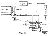
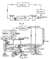
- a subcooler (10) for the liquid refrigerant and a precooler (11) for the hot gas refrigerant relies on an evaporative cooling process that will be used twice; a first use of the dry, cold building exhaust air (or alternatively outdoor air, Fig 4b) and condensate (or other) water supply that will first evaporatively cool the subcool heat exchanger which in turn cools the liquid refrigerant flowing through the subcooler and then the air supply passing out of the subcooler will flow through the wetted (or alternatively dry) precooler to evaporatively (or alternatively sensibly) cool the precool heat exchanger which in turn cools the hot gas refrigerant flowing through the precooler.
- the subcooler and precooler to be connected in serial communication in the refrigeration cycle as shown in Fig. 4.
- the precooler may or may not be wetted for this secondary use of the air discharging through the subcooler. If not wetted, the precool heat exchanger is sensibly cooled by the exhaust air supply, exiting the subcooler only.
- a subcooler (10) for the liquid refrigerant and a postheater for the suction gas and liquid refrigerant rely on a sensible (conductive) cooling of the liquid refrigerant by means of passing the building exhaust air, which is cool relative to the liquid refrigerant temperature, through the subcool heat exchanger which in turn subcools the liquid refrigerant flowing through the subcooler and in turn further heats the outgoing building exhaust air.
- Fig. 5b illustrates the same relationship between a subcooler (10) and a postheater (12) as in Fig. 5a, but illustrates the use of outside air to first subcool the liquid refrigerant and then using the subcooler warmed air to postheat the low pressure side gas and liquid refrigerant flowing through said postheater.
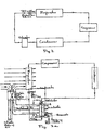
- Fig. 6 is illustrative of some of the possible pump and control mechanisms for controlling the flow of condensate (or other) water across the subcooler and/or precooler heat exchangers.
- the methods illustrated include a mechanically pumped method whereby water is distributed across the top of the subcool and/or precool heat exchangers and allowed to flow down through the heat exchanger(s), perpendicular to the flow of the cold, dry building exhaust air.
- Fig. 7 is illustrative of a capillary feed method that pulls water up onto the surface of the heat exchangers by means of the surface tension of water.
- the increased efficiency of the refrigeration cycle due to precooling is due to, lower head pressure, higher compressor efficiency and more efficient use of the primary condenser.
- the unique and innovative use of the cold, dry building exhaust air (or alternatively outdoor air) required for good indoor air quality and the use of condensate (or other) water to accomplish precooling evaporatively , or to accomplish precooling by using the exhaust air(or outside air) after first use in the subcooler or conductively using only the exhaust air after subcooling, is extremely cost effective.
Landscapes
- Engineering & Computer Science (AREA)
- Mechanical Engineering (AREA)
- General Engineering & Computer Science (AREA)
- Chemical & Material Sciences (AREA)
- Combustion & Propulsion (AREA)
- Physics & Mathematics (AREA)
- Thermal Sciences (AREA)
- Other Air-Conditioning Systems (AREA)
- Heat-Pump Type And Storage Water Heaters (AREA)
- Central Air Conditioning (AREA)
- Compression-Type Refrigeration Machines With Reversible Cycles (AREA)
- Filling Or Discharging Of Gas Storage Vessels (AREA)
Abstract
Description
Claims (5)
- A heat exchange refrigerant subcool and/or precool system configured for receiving cold, dry building exhaust air, and stored condensate water from an air conditioner, refrigeration or heat pump system or other water supply that includes a condenser, an evaporator, a compressor and a refrigerant and that produces condensate water that is then stored ,
wherein the heat exchange refrigerant subcool and/or precool system comprises in combination:a) a heat exchanger configured such that the condensate water is pumped across the heat exchanger while the cold, dry building exhaust air is passed over said heat exchanger for at least one of (1) evaporatively subcooling a liquid refrigerant that has already passed through the condenser of said air conditioner, refrigeration or heat pump system and (2) evaporatively precooling hot gas refrigerant before said refrigerant passes into the condenser of said air conditioner, refrigeration or heat pump system, wherein the heat exchanger is in the form of one or both of (i) a subcooler adapted to be serially connected in fluid communication with the output of the condenser and input to the evaporator of said air conditioner, refrigeration or heat pump system, enabling the refrigerant in said system to flow through said subcooler after first flowing through the condenser or (ii) a precooler adapted to be serially connected in fluid communication with the output of the compressor and the input of the condenser of said air conditioner, refrigeration or heat pump system, enabling hot gas refrigerant to flow through said precooler before passing into the condenser;b) means for flowing the condensate and make up water, said means comprising one or more of (1) a reservoir located below one or both of the subcooler and the precooler that receives the condensate discharge from said air conditioner, refrigeration or heat pump and that also receives any needed make up water; each respective said reservoir being connected in fluid communication with the input of a pump that pumps stored condensate and make up water through a control system that enables the correct amount of water to flow across and wet the surface of, respectively, said subcooler and/or said precooler and then back to storage in the reservoir and (2) a capillary feed configured such that the bottom of one or both of said subcooler and said precooler is placed in a water storage tank that receives the condensate water from said air conditioner, refrigeration or heat pump and any needed make up water, for capillary feeding of said water to wet the surface of, respectively, said subcooler and/or the precooler;c) one or both of said wetted subcooler and said precooler is connected in fluid communication with the cold, dry building exhaust air that subsequently cools by evaporation the water flowing over one or both of the subcooler and the precooler which in turn cools the refrigerant in one or both of the subcooler and the precooler; andd) a means for said water to overflow to discharge, whereby one or both of said subcooler and said precooler utilizes said evaporative cooling process for providing, respectively, maximum available subcooling to the liquid refrigerant and/or maximum available precooling of the refrigerant of an air conditioner, refrigeration or heat pump system. - A heat exchange refrigerant subcool system as claimed in claim 1 wherein the means for flowing the condensate and make up water comprises a reservoir located below one or both of the subcooler and the precooler that receives the condensate discharge from said air conditioner, refrigeration or heat pump and that also receives any needed make up water; each respective said reservoir being connected in fluid communication with the input of a pump that pumps stored condensate and make up water through a control system that enables the correct amount of water to flow across and wet the surface of, respectively, said subcooler and/or said precooler and then back to storage in the reservoir.
- A heat exchange refrigerant subcool system as set forth in claim 1 wherein the means for flowing the condensate and make up water through a control system comprises a capillary feed configured such that the bottom of one or both of said subcooler and said precooler is placed in a water storage tank that receives the condensate water from said air conditioner, refrigeration or heat pump and any needed make up water, for capillary feeding of said water to wet the surface of, respectively, said subcooler and/or the precooler.
- A combination subcool and precool heat exchanger system as claimed in claim 1 comprising in combination:wherein the system is configured to utilize the stored condensate water from the air conditioner, refrigeration or heat pump system and any needed make-up water by first pumping it across the first heat exchanger while the cold, dry building exhaust air is also passed over said first heat exchanger for first evaporatively subcooling the liquid refrigerant that has passed through the condenser of said air conditioner, refrigeration or heat pump system and is configured then to pass the air exhausting from the first heat exchanger through the second water wetted heat exchanger (the precooler) for subsequently precooling the hot gas discharge refrigerant from the compressor before said refrigerant passes into the condenser of said air conditioner, refrigeration or heat pump system.a) a first heat exchanger, the subcooler serially connected in fluid communication with the output of the condenser and the input to the evaporator, enabling the refrigerant to flow through said subcooler after first flowing through the condenser and then the evaporator;b) a second heat exchanger, the precooler serially connected in fluid communication with the output of a compressor and the input to the condenser, enabling the hot gas refrigerant to flow from the compressor through said precooler before passing into the condenser;c) a reservoir system below the subcooler and precooler that receives the condensate and make-up water supplies;d) said reservoir system connected in fluid communication with the input of a pump that pumps stored condensate and make-up water through a control system that enables the correct amount of condensate and/or make-up water to flow across and wet the surfaces of said subcooler and said precooler;e) said subcooler further connected in fluid communication with cold, dry building exhaust air that subsequently cools by evaporation the water flowing over the subcooler which in turn cools the liquid refrigerant in the subcooler;f) said precooler connected in fluid communication with the airflow output of the subcooler of the previously used building exhaust air, said previously used building exhaust air passing through said condensate and make-up water supply wetted precooler heat exchanger, where said exhaust air cools by evaporation the water flowing over the precooler which in turn precools the hot gas refrigerant flowing through the precooler: andg) means for said condensate and make-up water to overflow to discharge, whereby said subcool and precool system utilizes said evaporative cooling for providing maximum available subcooling to the liquid refrigerant and maximum available precooling to the hot gas discharge refrigerant of said air conditioner; refrigeration or heat pump system,
- A heat exchange refrigerant subcool and/or precool method comprising(a) receiving cold, dry building exhaust air,(b) receiving stored condensate water from an air conditioner, refrigeration or heat pump system or other water supply that includes a condenser, an evaporator, a compressor and a refrigerant and that produces condensate water that is then stored,(c) flowing the condensate water across a heat exchanger while the cold, dry building exhaust air is passed over said heat exchanger for at least one of (1) evaporatively subcooling a liquid refrigerant that has already passed through the condenser of said air conditioner, refrigeration or heat pump system and (2) evaporatively precooling hot gas refrigerant before said refrigerant passes into the condenser of said air conditioner, refrigeration or heat pump system,(d) wherein the heat exchanger is in the form of one or both of (i) a subcooler adapted to be serially connected in fluid communication with the output of the condenser and input to the evaporator of said air conditioner, refrigeration or heat pump system, enabling the refrigerant in said system to flow through said subcooler after first flowing through the condenser or (ii) a precooler adapted to be serially connected in fluid communication with the output of the compressor and the input of the condenser of said air conditioner, refrigeration or heat pump system, enabling hot gas refrigerant to flow through said precooler before passing into the condenser;(e) flowing the condensate and make up water over one or both of the precooler and the subcooler, said flowing comprising either (1) pumping the condensate discharge from said air conditioner, refrigeration or heat pump and any needed make up water from a reservoir located below one or both of the subcooler and the precooler to flow across and wet the surface of, respectively said subcooler and/or the precooler and then back to storage in the reservoir, said water passing through a control system that enables the correct amount of water to flow across and wet the surface of, respectively said subcooler and/or the precooler and (2) capillary feeding condensate water from said air conditioner, refrigeration or heat pump and any needed make up water from a water storage tank in which the bottom of one or both of said subcooler and said precooler is placed to wet the surface of, respectively, said subcooler and/or said precooler;(f) connecting one or both of said wetted subcooler and said precooler in fluid communication with the cold, dry building exhaust air that cools by evaporation the water flowing over one or both of the subcooler and the precooler which in turn cools the refrigerant in one or both of the subcooler and the precooler; and(g) allowing said water to overflow to discharge, whereby one or both of said subcooler and said precooler utilizes said evaporative cooling process for providing maximum available subcooling to the liquid refrigerant and/or maximum available precooling of the refrigerant, respectively, of an air conditioner, refrigeration or heat pump system.
Applications Claiming Priority (3)
| Application Number | Priority Date | Filing Date | Title |
|---|---|---|---|
| US168822 | 1988-03-16 | ||
| US09/168,822 US6070423A (en) | 1998-10-08 | 1998-10-08 | Building exhaust and air conditioner condenstate (and/or other water source) evaporative refrigerant subcool/precool system and method therefor |
| PCT/US1999/023394 WO2000020809A1 (en) | 1998-10-08 | 1999-10-07 | Building exhaust and air conditioner condensate |
Publications (3)
| Publication Number | Publication Date |
|---|---|
| EP1121565A2 EP1121565A2 (en) | 2001-08-08 |
| EP1121565A4 EP1121565A4 (en) | 2002-02-20 |
| EP1121565B1 true EP1121565B1 (en) | 2005-12-14 |
Family
ID=22613079
Family Applications (1)
| Application Number | Title | Priority Date | Filing Date |
|---|---|---|---|
| EP99951841A Expired - Lifetime EP1121565B1 (en) | 1998-10-08 | 1999-10-07 | heat exchange refrigerant subcool and/or precool system and method |
Country Status (9)
| Country | Link |
|---|---|
| US (1) | US6070423A (en) |
| EP (1) | EP1121565B1 (en) |
| CN (1) | CN100354582C (en) |
| AT (1) | ATE313050T1 (en) |
| AU (1) | AU748789B2 (en) |
| BR (1) | BR9914371A (en) |
| DE (1) | DE69928955T2 (en) |
| ES (1) | ES2251231T3 (en) |
| WO (1) | WO2000020809A1 (en) |
Cited By (1)
| Publication number | Priority date | Publication date | Assignee | Title |
|---|---|---|---|---|
| EP3436748B1 (en) * | 2016-04-01 | 2023-10-18 | HVPS Holdings (Pty) Limited | An air conditioning system |
Families Citing this family (32)
| Publication number | Priority date | Publication date | Assignee | Title |
|---|---|---|---|---|
| US7150160B2 (en) | 1998-10-08 | 2006-12-19 | Global Energy Group, Inc. | Building exhaust and air conditioner condensate (and/or other water source) evaporative refrigerant subcool/precool system and method therefor |
| US6324862B1 (en) * | 2000-01-31 | 2001-12-04 | Julio A. Monjes | Air cooler by enhanced evaporation and heater |
| US6318108B1 (en) * | 2000-09-27 | 2001-11-20 | George L. Holstein | Self-washing coil for air conditioning units |
| DE10103150B4 (en) * | 2001-01-24 | 2015-12-10 | Stiebel Eltron Gmbh & Co. Kg | ventilation |
| EP1331458A1 (en) * | 2002-01-24 | 2003-07-30 | Süddeutsche Etna-Werk Gmbh | Ventilator and method for controlling the ventilator |
| US6595011B1 (en) | 2002-05-02 | 2003-07-22 | Linda Forgy Chaney | Water cooled air conditioner |
| US7013658B2 (en) * | 2004-02-03 | 2006-03-21 | Carrier Corporation | Refrigerant subcooling by condensate |
| CN100381768C (en) * | 2005-02-21 | 2008-04-16 | 海尔集团公司 | Method for increasing refrigerating quantity and reducing power of air conditioner and air conditioning device |
| US7266968B2 (en) * | 2005-06-07 | 2007-09-11 | Chin Piao Huang | Air conditioner having water draining device |
| US7854141B1 (en) | 2008-12-08 | 2010-12-21 | Breen Joseph G | Energy conservation in a self-contained air-conditioning unit |
| AU2010225956B2 (en) * | 2009-03-19 | 2012-11-15 | Daikin Industries, Ltd. | Air conditioning apparatus |
| JP5647396B2 (en) * | 2009-03-19 | 2014-12-24 | ダイキン工業株式会社 | Air conditioner |
| US8561420B2 (en) * | 2009-05-08 | 2013-10-22 | Honda Motor Co., Ltd. | Evaporator assembly for an HVAC system |
| US9310087B2 (en) * | 2009-09-29 | 2016-04-12 | Carrier Corporation | System and method for maintaining air temperature within a building HVAC system |
| DE102010028315A1 (en) * | 2010-04-28 | 2011-11-03 | Siemens Aktiengesellschaft | Method for the thermodynamic online diagnosis of a large-scale plant |
| JP5747567B2 (en) * | 2011-03-04 | 2015-07-15 | 富士電機株式会社 | Refrigerant circuit device |
| US9322600B2 (en) | 2011-03-17 | 2016-04-26 | Olive Tree Patents 1 Llc | Thermosyphon heat recovery |
| US20120047936A1 (en) * | 2011-04-18 | 2012-03-01 | General Electric Company | Appliance refrigeration system with final condenser |
| WO2013056103A2 (en) * | 2011-10-12 | 2013-04-18 | Ringdale, Inc. | Room cooling system |
| TWI452246B (en) * | 2011-11-14 | 2014-09-11 | Ind Tech Res Inst | Heat pump hot water system |
| EP2836781A4 (en) * | 2012-03-06 | 2016-01-20 | Mestek Inc | Evaporative cooling system and device |
| PL2965020T3 (en) * | 2013-03-07 | 2018-11-30 | Zehnder Group International Ag | System for conditioning the air in a building |
| US10119738B2 (en) | 2014-09-26 | 2018-11-06 | Waterfurnace International Inc. | Air conditioning system with vapor injection compressor |
| CN105180433B (en) * | 2015-10-21 | 2017-11-17 | 杭州佳力斯韦姆新能源科技有限公司 | Realize high return water temperature and the Trans-critical cycle CO of two kinds of heating condition requirements2Heat pump and its control method |
| US10871314B2 (en) | 2016-07-08 | 2020-12-22 | Climate Master, Inc. | Heat pump and water heater |
| US10866002B2 (en) | 2016-11-09 | 2020-12-15 | Climate Master, Inc. | Hybrid heat pump with improved dehumidification |
| CN107687715A (en) * | 2017-07-28 | 2018-02-13 | 珠海格力电器股份有限公司 | Air conditioning system and control method thereof |
| US10935260B2 (en) | 2017-12-12 | 2021-03-02 | Climate Master, Inc. | Heat pump with dehumidification |
| US11592215B2 (en) | 2018-08-29 | 2023-02-28 | Waterfurnace International, Inc. | Integrated demand water heating using a capacity modulated heat pump with desuperheater |
| CA3081986A1 (en) | 2019-07-15 | 2021-01-15 | Climate Master, Inc. | Air conditioning system with capacity control and controlled hot water generation |
| CN110425776A (en) * | 2019-08-19 | 2019-11-08 | 北京丰联奥睿科技有限公司 | A kind of V-type vertical tube evaporative cooling tower and its double control air-conditioning system |
| CN114893828B (en) * | 2022-03-30 | 2023-08-18 | 青岛海信日立空调系统有限公司 | Air conditioner |
Family Cites Families (33)
| Publication number | Priority date | Publication date | Assignee | Title |
|---|---|---|---|---|
| US1891538A (en) * | 1931-12-26 | 1932-12-20 | Mccord Radiator & Mfg Co | Evaporator |
| US2124291A (en) * | 1935-04-01 | 1938-07-19 | Walter L Fleisher | Method of air conditioning |
| US2255585A (en) * | 1937-12-27 | 1941-09-09 | Borg Warner | Method of and apparatus for heat transfer |
| US2350408A (en) * | 1941-05-28 | 1944-06-06 | Honeywell Regulator Co | Direct expansion air conditioning control system |
| US2351695A (en) * | 1942-04-17 | 1944-06-20 | Honeywell Regulator Co | Multizone air conditioning system |
| US2776543A (en) * | 1954-05-10 | 1957-01-08 | Gen Electric | Step-modulated control system for air conditioning apparatus |
| US2938361A (en) * | 1957-09-13 | 1960-05-31 | Borg Warner | Reversible refrigerating system |
| US3264839A (en) * | 1964-05-12 | 1966-08-09 | Westinghouse Electric Corp | Heat pumps for simultaneous cooling and heating |
| US3537274A (en) * | 1968-10-18 | 1970-11-03 | Alco Controls Corp | Dual evaporator refrigeration system |
| US3902551A (en) * | 1974-03-01 | 1975-09-02 | Carrier Corp | Heat exchange assembly and fin member therefor |
| US4023949A (en) * | 1975-08-04 | 1977-05-17 | Schlom Leslie A | Evaporative refrigeration system |
| US4173865A (en) * | 1978-04-25 | 1979-11-13 | General Electric Company | Auxiliary coil arrangement |
| AU538000B2 (en) * | 1979-04-02 | 1984-07-26 | Matsushita Electric Industrial Co., Ltd. | Air conditioner |
| US4280334A (en) * | 1979-06-26 | 1981-07-28 | Lakdawala Ness R | Water condensate recovery device |
| GB2056652B (en) * | 1979-07-02 | 1983-05-11 | Gen Motors Corp | Hollow-plate heat exchanger |
| US4679404A (en) * | 1979-07-31 | 1987-07-14 | Alsenz Richard H | Temperature responsive compressor pressure control apparatus and method |
| JPS6050246B2 (en) * | 1979-08-08 | 1985-11-07 | 株式会社東芝 | Refrigeration equipment |
| US4599870A (en) * | 1981-03-25 | 1986-07-15 | Hebert Theodore M | Thermosyphon heat recovery |
| US4373346A (en) * | 1981-03-25 | 1983-02-15 | Hebert Thomas H | Precool/subcool system and condenser therefor |
| US4380910A (en) * | 1981-08-13 | 1983-04-26 | Aztech International, Ltd. | Multi-stage indirect-direct evaporative cooling process and apparatus |
| US4574868A (en) * | 1981-10-02 | 1986-03-11 | Caterpillar Tractor Co. | Flow directing element for heat exchanger |
| WO1983001997A1 (en) * | 1981-11-30 | 1983-06-09 | Anders, Gene, A. | Heat exchanger core with varied-angle tubes |
| US4623949A (en) * | 1985-09-06 | 1986-11-18 | Westinghouse Electric Corp. | Bus differential relay |
| US5279360A (en) * | 1985-10-02 | 1994-01-18 | Modine Manufacturing Co. | Evaporator or evaporator/condenser |
| US4910971A (en) * | 1988-02-05 | 1990-03-27 | Hydro Thermal Engineering Pty. Ltd. | Indirect air conditioning system |
| US4873837A (en) * | 1988-10-03 | 1989-10-17 | Chrysler Motors Corporation | Dual evaporator air conditioner |
| US5113668A (en) * | 1989-07-07 | 1992-05-19 | Advanced Cooling Technology, Inc. | Refrigeration system with evaporative subcooling |
| US5509272A (en) * | 1991-03-08 | 1996-04-23 | Hyde; Robert E. | Apparatus for dehumidifying air in an air-conditioned environment with climate control system |
| US5205347A (en) * | 1992-03-31 | 1993-04-27 | Modine Manufacturing Co. | High efficiency evaporator |
| US5465591A (en) * | 1992-08-14 | 1995-11-14 | Whirlpool Corporation | Dual evaporator refrigerator with non-simultaneous evaporator |
| IT1263813B (en) * | 1993-01-25 | 1996-09-03 | HEAT EXCHANGER, PARTICULARLY FOR USE AS A SHELVED EVAPORATOR IN REFRIGERATOR OR FREEZER CABINETS AND PROCEDURE FOR ITS REALIZATION | |
| US5345778A (en) * | 1993-05-07 | 1994-09-13 | Hussmann Corporation | Low temperature display merchandiser |
| US5613554A (en) * | 1995-06-23 | 1997-03-25 | Heatcraft Inc. | A-coil heat exchanger |
-
1998
- 1998-10-08 US US09/168,822 patent/US6070423A/en not_active Expired - Lifetime
-
1999
- 1999-10-07 CN CNB998141836A patent/CN100354582C/en not_active Expired - Fee Related
- 1999-10-07 AU AU64196/99A patent/AU748789B2/en not_active Ceased
- 1999-10-07 DE DE69928955T patent/DE69928955T2/en not_active Expired - Fee Related
- 1999-10-07 WO PCT/US1999/023394 patent/WO2000020809A1/en active IP Right Grant
- 1999-10-07 ES ES99951841T patent/ES2251231T3/en not_active Expired - Lifetime
- 1999-10-07 BR BR9914371-2A patent/BR9914371A/en active Search and Examination
- 1999-10-07 EP EP99951841A patent/EP1121565B1/en not_active Expired - Lifetime
- 1999-10-07 AT AT99951841T patent/ATE313050T1/en not_active IP Right Cessation
Cited By (2)
| Publication number | Priority date | Publication date | Assignee | Title |
|---|---|---|---|---|
| EP3436748B1 (en) * | 2016-04-01 | 2023-10-18 | HVPS Holdings (Pty) Limited | An air conditioning system |
| US11965662B2 (en) | 2016-04-01 | 2024-04-23 | Hvps Holdings (Pty) Limited | Air conditioning system |
Also Published As
| Publication number | Publication date |
|---|---|
| ES2251231T3 (en) | 2006-04-16 |
| WO2000020809A1 (en) | 2000-04-13 |
| US6070423A (en) | 2000-06-06 |
| WO2000020809A9 (en) | 2001-09-27 |
| WO2000020809A8 (en) | 2001-03-08 |
| AU6419699A (en) | 2000-04-26 |
| ATE313050T1 (en) | 2005-12-15 |
| DE69928955D1 (en) | 2006-01-19 |
| DE69928955T2 (en) | 2006-08-24 |
| EP1121565A2 (en) | 2001-08-08 |
| CN1329708A (en) | 2002-01-02 |
| AU748789B2 (en) | 2002-06-13 |
| EP1121565A4 (en) | 2002-02-20 |
| CN100354582C (en) | 2007-12-12 |
| BR9914371A (en) | 2002-01-02 |
Similar Documents
| Publication | Publication Date | Title |
|---|---|---|
| EP1121565B1 (en) | heat exchange refrigerant subcool and/or precool system and method | |
| US7150160B2 (en) | Building exhaust and air conditioner condensate (and/or other water source) evaporative refrigerant subcool/precool system and method therefor | |
| US6857285B2 (en) | Building exhaust and air conditioner condensate (and/or other water source) evaporative refrigerant subcool/precool system and method therefor | |
| US6167715B1 (en) | Direct refrigerant geothermal heat exchange or multiple source subcool/postheat/precool system therefor | |
| US6460358B1 (en) | Flash gas and superheat eliminator for evaporators and method therefor | |
| US6237359B1 (en) | Utilization of harvest and/or melt water from an ice machine for a refrigerant subcool/precool system and method therefor | |
| JP3662557B2 (en) | Heat pump system | |
| US6116048A (en) | Dual evaporator for indoor units and method therefor | |
| CN107014015B (en) | Recovery type heat evaporating condensation type handpiece Water Chilling Units | |
| US5297397A (en) | Efficiency directed supplemental condensing for high ambient refrigeration operation | |
| EP1859208A1 (en) | Hvac system with powered subcooler | |
| US5775114A (en) | Figure 8-form thermodynamic cycle air conditioner | |
| JP2003004321A (en) | Refrigerating air conditioner | |
| KR20030045175A (en) | Phase-change Heat Transfer Coupling For Aqua-ammonia Absorption Systems | |
| JPH0953864A (en) | Engine type cooling device | |
| KR100965114B1 (en) | Heating and cooling system | |
| KR100493871B1 (en) | Equipment for dehumidification and dryness | |
| KR100534003B1 (en) | Heating and cooling system using brine circulation | |
| JPS6040583B2 (en) | air conditioner | |
| KR200350499Y1 (en) | Heating and cooling system using brine circulation | |
| KR20160107714A (en) | System for preserving temperature and humidity | |
| KR910002288Y1 (en) | Heat pump | |
| JPS61276662A (en) | Heat pump type water heater | |
| JPH01219438A (en) | Direct contact type cooling and heating device | |
| JPS5886370A (en) | Refrigerator |
Legal Events
| Date | Code | Title | Description |
|---|---|---|---|
| PUAI | Public reference made under article 153(3) epc to a published international application that has entered the european phase |
Free format text: ORIGINAL CODE: 0009012 |
|
| 17P | Request for examination filed |
Effective date: 20010426 |
|
| AK | Designated contracting states |
Kind code of ref document: A2 Designated state(s): AT BE CH CY DE DK ES FI FR GB GR IE IT LI LU MC NL PT SE |
|
| AX | Request for extension of the european patent |
Free format text: AL;LT;LV;MK;RO;SI |
|
| RIC1 | Information provided on ipc code assigned before grant |
Free format text: 7F 25B 7/00 A, 7F 25B 40/00 B, 7F 24F 12/00 B |
|
| A4 | Supplementary search report drawn up and despatched |
Effective date: 20020109 |
|
| AK | Designated contracting states |
Kind code of ref document: A4 Designated state(s): AT BE CH CY DE DK ES FI FR GB GR IE IT LI LU MC NL PT SE |
|
| 17Q | First examination report despatched |
Effective date: 20040204 |
|
| RAP1 | Party data changed (applicant data changed or rights of an application transferred) |
Owner name: GLOBAL ENERGY & ENVIRONMENTAL RESEARCH, INC. |
|
| RIN1 | Information on inventor provided before grant (corrected) |
Inventor name: GLOBAL ENERGY & ENVIRONMENTAL RESEARCH, INC. |
|
| RAP1 | Party data changed (applicant data changed or rights of an application transferred) |
Owner name: GLOBAL ENERGY GROUP, INC. |
|
| RIN1 | Information on inventor provided before grant (corrected) |
Inventor name: HEBERT, THOMAS, H. |
|
| GRAP | Despatch of communication of intention to grant a patent |
Free format text: ORIGINAL CODE: EPIDOSNIGR1 |
|
| RTI1 | Title (correction) |
Free format text: HEAT EXCHANGE REFRIGERANT SUBCOOL AND/OR PRECOOL SYSTEM AND METHOD |
|
| GRAS | Grant fee paid |
Free format text: ORIGINAL CODE: EPIDOSNIGR3 |
|
| GRAA | (expected) grant |
Free format text: ORIGINAL CODE: 0009210 |
|
| AK | Designated contracting states |
Kind code of ref document: B1 Designated state(s): AT BE CH CY DE DK ES FI FR GB GR IE IT LI LU MC NL PT SE |
|
| PG25 | Lapsed in a contracting state [announced via postgrant information from national office to epo] |
Ref country code: LI Free format text: LAPSE BECAUSE OF FAILURE TO SUBMIT A TRANSLATION OF THE DESCRIPTION OR TO PAY THE FEE WITHIN THE PRESCRIBED TIME-LIMIT Effective date: 20051214 Ref country code: IT Free format text: LAPSE BECAUSE OF FAILURE TO SUBMIT A TRANSLATION OF THE DESCRIPTION OR TO PAY THE FEE WITHIN THE PRESCRIBED TIME-LIMIT;WARNING: LAPSES OF ITALIAN PATENTS WITH EFFECTIVE DATE BEFORE 2007 MAY HAVE OCCURRED AT ANY TIME BEFORE 2007. THE CORRECT EFFECTIVE DATE MAY BE DIFFERENT FROM THE ONE RECORDED. Effective date: 20051214 Ref country code: FI Free format text: LAPSE BECAUSE OF FAILURE TO SUBMIT A TRANSLATION OF THE DESCRIPTION OR TO PAY THE FEE WITHIN THE PRESCRIBED TIME-LIMIT Effective date: 20051214 Ref country code: CH Free format text: LAPSE BECAUSE OF FAILURE TO SUBMIT A TRANSLATION OF THE DESCRIPTION OR TO PAY THE FEE WITHIN THE PRESCRIBED TIME-LIMIT Effective date: 20051214 Ref country code: BE Free format text: LAPSE BECAUSE OF FAILURE TO SUBMIT A TRANSLATION OF THE DESCRIPTION OR TO PAY THE FEE WITHIN THE PRESCRIBED TIME-LIMIT Effective date: 20051214 Ref country code: AT Free format text: LAPSE BECAUSE OF FAILURE TO SUBMIT A TRANSLATION OF THE DESCRIPTION OR TO PAY THE FEE WITHIN THE PRESCRIBED TIME-LIMIT Effective date: 20051214 |
|
| REG | Reference to a national code |
Ref country code: GB Ref legal event code: FG4D |
|
| REG | Reference to a national code |
Ref country code: CH Ref legal event code: EP |
|
| REG | Reference to a national code |
Ref country code: IE Ref legal event code: FG4D |
|
| REF | Corresponds to: |
Ref document number: 69928955 Country of ref document: DE Date of ref document: 20060119 Kind code of ref document: P |
|
| PG25 | Lapsed in a contracting state [announced via postgrant information from national office to epo] |
Ref country code: SE Free format text: LAPSE BECAUSE OF FAILURE TO SUBMIT A TRANSLATION OF THE DESCRIPTION OR TO PAY THE FEE WITHIN THE PRESCRIBED TIME-LIMIT Effective date: 20060314 Ref country code: DK Free format text: LAPSE BECAUSE OF FAILURE TO SUBMIT A TRANSLATION OF THE DESCRIPTION OR TO PAY THE FEE WITHIN THE PRESCRIBED TIME-LIMIT Effective date: 20060314 |
|
| REG | Reference to a national code |
Ref country code: ES Ref legal event code: FG2A Ref document number: 2251231 Country of ref document: ES Kind code of ref document: T3 |
|
| REG | Reference to a national code |
Ref country code: GR Ref legal event code: EP Ref document number: 20060400824 Country of ref document: GR |
|
| REG | Reference to a national code |
Ref country code: CH Ref legal event code: PL |
|
| ET | Fr: translation filed | ||
| PG25 | Lapsed in a contracting state [announced via postgrant information from national office to epo] |
Ref country code: IE Free format text: LAPSE BECAUSE OF NON-PAYMENT OF DUE FEES Effective date: 20061009 |
|
| PLBE | No opposition filed within time limit |
Free format text: ORIGINAL CODE: 0009261 |
|
| STAA | Information on the status of an ep patent application or granted ep patent |
Free format text: STATUS: NO OPPOSITION FILED WITHIN TIME LIMIT |
|
| PG25 | Lapsed in a contracting state [announced via postgrant information from national office to epo] |
Ref country code: MC Free format text: LAPSE BECAUSE OF NON-PAYMENT OF DUE FEES Effective date: 20061031 |
|
| PGFP | Annual fee paid to national office [announced via postgrant information from national office to epo] |
Ref country code: IT Payment date: 20061031 Year of fee payment: 8 |
|
| 26N | No opposition filed |
Effective date: 20060915 |
|
| PG25 | Lapsed in a contracting state [announced via postgrant information from national office to epo] |
Ref country code: NL Free format text: LAPSE BECAUSE OF NON-PAYMENT OF DUE FEES Effective date: 20070501 Ref country code: DE Free format text: LAPSE BECAUSE OF NON-PAYMENT OF DUE FEES Effective date: 20070501 |
|
| GBPC | Gb: european patent ceased through non-payment of renewal fee |
Effective date: 20061007 |
|
| NLV4 | Nl: lapsed or anulled due to non-payment of the annual fee |
Effective date: 20070501 |
|
| PG25 | Lapsed in a contracting state [announced via postgrant information from national office to epo] |
Ref country code: PT Free format text: LAPSE BECAUSE OF NON-PAYMENT OF DUE FEES Effective date: 20070709 |
|
| REG | Reference to a national code |
Ref country code: PT Ref legal event code: MM4A Free format text: LAPSE DUE TO NON-PAYMENT OF FEES Effective date: 20070709 |
|
| REG | Reference to a national code |
Ref country code: IE Ref legal event code: MM4A |
|
| REG | Reference to a national code |
Ref country code: FR Ref legal event code: ST Effective date: 20070629 |
|
| PG25 | Lapsed in a contracting state [announced via postgrant information from national office to epo] |
Ref country code: GB Free format text: LAPSE BECAUSE OF NON-PAYMENT OF DUE FEES Effective date: 20061007 |
|
| REG | Reference to a national code |
Ref country code: ES Ref legal event code: FD2A Effective date: 20061009 |
|
| PG25 | Lapsed in a contracting state [announced via postgrant information from national office to epo] |
Ref country code: GR Free format text: LAPSE BECAUSE OF NON-PAYMENT OF DUE FEES Effective date: 20060315 Ref country code: FR Free format text: LAPSE BECAUSE OF NON-PAYMENT OF DUE FEES Effective date: 20061031 Ref country code: ES Free format text: LAPSE BECAUSE OF NON-PAYMENT OF DUE FEES Effective date: 20061009 |
|
| PG25 | Lapsed in a contracting state [announced via postgrant information from national office to epo] |
Ref country code: CY Free format text: LAPSE BECAUSE OF NON-PAYMENT OF DUE FEES Effective date: 20061007 |
|
| PG25 | Lapsed in a contracting state [announced via postgrant information from national office to epo] |
Ref country code: LU Free format text: LAPSE BECAUSE OF NON-PAYMENT OF DUE FEES Effective date: 20061007 |
|
| PG25 | Lapsed in a contracting state [announced via postgrant information from national office to epo] |
Ref country code: IT Free format text: LAPSE BECAUSE OF NON-PAYMENT OF DUE FEES Effective date: 20071007 |