EP1120927A2 - Empfänger und Verfahren zur Detektierung der empfangenen Leistung - Google Patents
Empfänger und Verfahren zur Detektierung der empfangenen Leistung Download PDFInfo
- Publication number
- EP1120927A2 EP1120927A2 EP01300626A EP01300626A EP1120927A2 EP 1120927 A2 EP1120927 A2 EP 1120927A2 EP 01300626 A EP01300626 A EP 01300626A EP 01300626 A EP01300626 A EP 01300626A EP 1120927 A2 EP1120927 A2 EP 1120927A2
- Authority
- EP
- European Patent Office
- Prior art keywords
- value
- output
- component
- output value
- reception signal
- Prior art date
- Legal status (The legal status is an assumption and is not a legal conclusion. Google has not performed a legal analysis and makes no representation as to the accuracy of the status listed.)
- Withdrawn
Links
Images



Classifications
-
- H—ELECTRICITY
- H04—ELECTRIC COMMUNICATION TECHNIQUE
- H04B—TRANSMISSION
- H04B17/00—Monitoring; Testing
- H04B17/30—Monitoring; Testing of propagation channels
- H04B17/309—Measuring or estimating channel quality parameters
- H04B17/318—Received signal strength
- H04B17/327—Received signal code power [RSCP]
Definitions
- the present invention relates to a receiver that detects an approximate value of the power of a reception signal. Especially, the invention relates to a receiver that enables detecting the highly precise approximate value with a high speed.
- a communication system it is indispensable to detect the power (level) of a reception signal by a relevant receiver.
- the powers of the signals that are received from a plurality of base-station devices that exist in the neighborhood thereof are detected and compared at all times with one another by the receiver.
- the receiver recognizes a base-station device, the power of which signal is maximum, to be an optimum base-station device. According to this recognition, the receiver selects that base-station device as an opponent device for its communication.
- a component I represents the absolute value of the component I
- a component Q represents the absolute value of the component Q.
- a component I represents the absolute value of the component I
- a component Q represents the absolute value of the component Q.
- the power P of the reception signal is given by the following equation no. 1.
- the component I and component Q of the reception signal mean two digital de-modulated signals, the phase difference between which is 90 degrees. Each of these digital de-modulated signals is obtained by de-modulating, for example, the reception signal that has been subjected to orthogonal modulation.
- Equation no an approximate equation that is frequently used is shown below as the equation no. 2.
- P represents the power (here, an approximate value) of the reception signal
- MAX (I, Q) represents a larger one of the value I and the value Q
- MIN (I, Q) represents a smaller one of the value I and the value Q.
- FIG. 5 illustration is made of an example of the procedure of the power approximate-operation process that is taken when the receiver makes its operation of an approximate value of the power of the reception signal by using the approximate equation shown as the equation no. 3.
- the component I and component Q of the reception signal are taken in as digital signals (step S21). And the value I and the value Q are compared with each other to determine which one of them is larger or smaller (step S22).
- step S25 the value that is obtained by shifting the value d by 1 bit rightward (i.e. the value that is obtained by multiplying the value d by 1/2) is set to be d' (step S25). And, operation of (c + d') is executed. And, the result of this operation is detected as the approximate value of the power of the reception signal (step S26).
- the mobile-station device that as described above is at all times detecting the power of the reception signal from each of the base-station devices that exist in the neighboring area upon that mobile-station device, because the error made from that detection is too large, the mobile-station device erroneously recognizes the base-station device that is not optimum as being an optimum base-station device. Resultantly, there was the inconvenience that the possibility that the mobile-station device would select that base-station device became high.
- the present invention has been made in order to solve the above-described conventional problems and has an object to provide a receiver that enables detecting a highly precise approximate value of the power of the reception signal with a high speed.
- Another object of the invention is to provide a receiver that comprises a digital circuit enabling high-precision and high-speed detection to be made as a preferred embodiment.
- the receiver according to the invention detects an approximate value of the power of the reception signal as follows.
- first operation means performs addition of a value, which is obtained by multiplying a smaller one of the component I value and the component Q value of the reception signal by 1/8, and a larger one of them.
- Second operation means performs addition of a value, which is obtained by multiplying a smaller one of the component I value and the component Q value of the reception signal by 1/2, and a value that is obtained by multiplying a larger one of them by 7/8.
- Detection means detects a larger one of the operation result of the first operation means and the operation result of the second operation means as an approximate value of the power of the reception signal.
- the above-described operation process does not contain, for example, self-multiplication operation and therefore suits a digital operation process, it is possible to perform the operation process with a high speed.
- the power of the reception signal can be detected with a high precision (i.e. a highly precise approximate value can be detected) compared to the conventional receiver. Therefore, a high quality of communication can be ensured.
- an approximate value of the power of the reception signal is detected by, for example, the following digital-circuit construction to thereby realize the highly precise and high-speed detection in the same way as has been described above.
- a first comparator compares a component I and component Q of the reception signal in scale and outputs a larger one of these component values as a first output value.
- the first comparator simultaneously outputs a small one of them as a second output value.
- a 3-bit shift register multiplies the first output value from the first comparator by 1/8, and a subtractor subtracts the output value from the 3-bit shift register from the first output value from the first comparator.
- a 1-bit shift register multiplies a second output value from the first comparator by 1/2.
- a 2-bit shift register multiplies the output value from the 1-bit shift register by 1/4.
- a first adder adds the first output value from the first comparator and the output value from the 2-bit shift register.
- a second adder adds the output value from the subtractor and the output value from the 1-bit shift register.
- a second comparator compares the output value from the first adder and the output value from the second adder and outputs a larger one of these output values as an approximate value of the power of the reception signal.
- Fig. 1 there is illustrated an example of the construction of the receiver according to this embodiment.
- This receiver comprises an antenna 1 for transmitting and receiving a radio signal, a reception part (RX part) 2 for performing de-modulation, etc. of the signal received by the antenna 1 into a component I signal and component Q signal, a base-band signal processing part 3 for performing base-band signal processing of the component I signal and component Q signal that are output from the RX par 2, and a power (POWER) operation processing part 4 for performing operation of an approximate value of the power of the reception signal by the use of the components I and Q that are output from the RX part 2.
- RX part reception part
- POWER power
- the featuring portion of the receiver of this embodiment is regarding the construction of the power operation processing part 4 and the process that is executed by this power operation processing part 4. This construction and process will hereafter be explained in detail.
- Fig. 2 there is illustrated an example of the construction of a digital circuit of the power operation processing part 4 of this embodiment.
- the power operation processing part 4 comprises two comparators 11, 18, three shift registers 12, 14, and 15, one subtractor 13, and two adders 16, 17.
- the first comparator 11 has a function to input an I component and Q component of a reception signal that is output from the RX part 2 and to compare the both components with each other to determine which is larger or smaller.
- the first comparator 11 has a function to output a larger one of those components to each of a 3-bit (3 bits) shift register 12, subtractor 13, and first adder 16 as a first output value.
- the first comparator 11 has a function to output a smaller one of those components to a 1-bit (1bit) shift register 14 as a second output value.
- the 3-bit shift register 12 has a function to shift the first output value input from the first comparator 11 by 3 bits rightward (i.e. to multiply it by 1/8) and to output the resulting value to the substractor 13.
- the subtractor 13 has a function to input the first output value from the first comparator 11 and also to input the by-1/8-multiplied value from the 3-bit shift register 12.
- the substractor 13 performs subtraction of the by-1/8-multiplied value from the first output value.
- the substractor 13 has a function to output the result (i.e. a value obtained by multiplying the first output value by 7/8) of this subtraction to the second adder 17.
- the 1-bit shift register 14 has the following function. Namely, the 1-bit shift register 14 inputs the second output value that is output from the first comparator and performs 1-bit rightward shift of that second output value (i.e. multiplies the second output value by 1/2). The 1-bit shift register 14 outputs the resulting value to the 2-bit (2 bits) shift register 15 and the second adder 17.
- the 2-bit shift register 15 has a function to input the by-1/2-multiplied value from the 1-bit shift register 14, to perform 2-bit rightward shift thereof (i.e. to perform 1/4 multiplication thereof), and to output the resulting value to the first adder 16.
- the first adder 16 has the following function. Namely, the first adder 16 inputs the first output value from the first comparator 11 and also inputs the by-1/4-multiplied value (the by-1/8-multiplied value of the second output value) from the 2-bit shift register 15. The first adder 16 adds the first output value and the by-1/4-multiplied value to thereby output the result of addition to the second comparator 18.
- the second adder 17 inputs the result of subtraction from the subtractor 13 and inputs the by-1/2-multiplied value from the 1-bit shift register 14.
- the second adder 17 adds the result of subtraction and the by-1/2-multiplied value and outputs the result of this addition to the second comparator 18.
- the second comparator 18 compares the result of addition that is output from the first adder 16 and the result of addition that is output from the second adder 17, with each other, to determine which is larger or smaller.
- the second comparator 18 thereby outputs a larger one of the both results of additions as an approximate value of the power of the reception signal.
- the value (a larger one of the two results of the above-described additions) that is output from the second comparator 18 is detected as the power (an approximate value) of the reception signal.
- the addition result P1 that is output from the first adder 16 is given by the following equation no. 4 while the addition result P2 that is output from the second adder 17 is given by the following equation no. 5. It is to be noted that the approximate equation that is given as the equation no. 4 or 5 is suitable for the execution of the digital operation process and so is easy to realize with the use of the digital circuit.
- the value that is output as the power (approximate value) P of the reception signal from the second comparator 18 is given as the following equation no. 6. It is to be noted that MAX (P1, P2) represents a larger one of the values P1 and P2.
- Fig. 3 there is illustrated an example of the procedure of the power approximate-operation process executed in the power operation processing part 4 of this embodiment.
- a component I and component Q of the reception signal are taken in as digital signals (step S1).
- the first comparator 11 compares the component I and the component Q with each other to determine which one of them is larger or smaller (step S2).
- the 3-bit shift register 12 outputs a value (i.e. a value obtained by multiplying the a by 1/8) a' that is obtained by shifting the a by 3 bits rightward (step S5).
- the 1-bit shift register 14 outputs a value (i.e. a value obtained by multiplying the b by 1/2) b' that is obtained by shifting the b by 1 bit rightward (step S7).
- the 2-bit shift register 15 outputs a value (i.e. a value obtained by multiplying the b' by 1/4 ) b" that is obtained by shifting the b' by 2 bits rightward (step S8).
- (a + b" ) (the equation (1) ) is calculated by the first adder 16, and (a'' + b') (the equation (2)) is calculated by the second adder 17 (step S9).
- the second comparator 18 compares these two calculation results (addition results) with each other to determine which one of these results is larger or smaller (step S10). And, a larger one of those results is selected and is output as an approximate value of the power of the reception signal (step S11, step S12).
- the receiver according to the invention has the feature of performing the calculation of an approximate value of the power of the reception signal by the use of a plurality of the approximate equations.
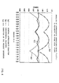
- Fig. 4 there is illustrated an example of the graphic diagram wherein comparison is made between the precision of the power approximate-operation that is executed in the receiver of this embodiment and the precision of the power approximate-operation that is executed in the conventional receiver by the use of the equation no. 3 shown under the item "Description of the Related Art".
- the abscissa axis of the graph represents the phase (radian (x ⁇ )), and the ordinate axis represents the power.
- the calculation error is large in value. So, the error that amounts even to 11.8 percent (%) at maximum inconveniently occurs. Further, in, for example, a mobile-station device, it sometimes happens that it becomes necessary to measure the SIR (Signal to Interference Ratio). However, when performing such a measurement, in the conventional receiver it results that a very large error inconveniently occurs because the error of that measurement is added to the above-described calculation error.
- SIR Signal to Interference Ratio
- the receiver of this embodiment using, for example, the digital circuit that has been constructed of the shift registers, comparator, etc. as illustrated in Fig . 2, a highly precise approximate value of the power of the reception signal can be detected with a high speed. It thereby becomes possible to ensure a high quality of communication.
- this comparator 18 constitutes detection means referred to in the invention.
- the approximate equation used in the invention is not limited to the embodiment of the equation nos. 4 to 6. If there is the feature of executing operations using, for example, a plurality of approximate equations to thereby calculate a plurality of candidates each becoming an approximate value of the power of the reception signal and thereby detect an excellent one from among a plurality of the candidates as an approximate value of the power of the reception signal, any approximate equations may be used. Also, no particular limitation is imposed on the construction of the receiver according to the invention, either. In the receiver according to the invention, for example, a construction to execute the operations using a DSP, CPU, etc. may also be adopted.
- the respective function means for executing the power approximate-operation process according to the invention have been constructed of the hardware circuit.
- the processor executes a control program stored in the ROM, thereby the process be executed.
- the invention can also be taken to be a recording medium from that data is readable by a relevant computer, such as a floppy disk or CD-ROM having stored therein such a control program. This control program can be input from the recording medium to the computer and be executed by the processor, thereby the process according to the invention can be performed.
- the receiver according to the invention can be applied not only to, for example, a mobile-station device of the radio communication system. The point is that only if a receiver is able to detect the power (an approximate value in case of the invention) of the reception signal, the receiver of the invention can be also applied to, for example, a base-station device, relay-station device, and other communication devices.
- a value obtained by multiplying a smaller one of the component I and the component Q of the reception signal by 1/8 and a larger one of these two components are added together according to a plurality of approximate equations.
- a value obtained by multiplying a smaller one of the components I and Q of the reception signal by 1/2 and a value obtained by multiplying a larger one of these components by 7/8 are added together similarly.
- the value of a larger one thereof is detected as an approximate value of the power of the reception signal. Therefore, for example, it is possible to detect a highly precise approximate value compared to the conventional receiver as illustrated in the above-described embodiment. Thereby, a highly precise and high-speed detection of the power can be realized.
Landscapes
- Engineering & Computer Science (AREA)
- Quality & Reliability (AREA)
- Physics & Mathematics (AREA)
- Electromagnetism (AREA)
- Computer Networks & Wireless Communication (AREA)
- Signal Processing (AREA)
- Circuits Of Receivers In General (AREA)
- Digital Transmission Methods That Use Modulated Carrier Waves (AREA)
- Monitoring And Testing Of Transmission In General (AREA)
Applications Claiming Priority (4)
| Application Number | Priority Date | Filing Date | Title |
|---|---|---|---|
| JP2000014281 | 2000-01-24 | ||
| JP2000014281 | 2000-01-24 | ||
| JP2001003739A JP4478340B2 (ja) | 2000-01-24 | 2001-01-11 | 受信機 |
| JP2001003739 | 2001-01-11 |
Publications (2)
| Publication Number | Publication Date |
|---|---|
| EP1120927A2 true EP1120927A2 (de) | 2001-08-01 |
| EP1120927A3 EP1120927A3 (de) | 2004-09-15 |
Family
ID=26584004
Family Applications (1)
| Application Number | Title | Priority Date | Filing Date |
|---|---|---|---|
| EP01300626A Withdrawn EP1120927A3 (de) | 2000-01-24 | 2001-01-24 | Empfänger und Verfahren zur Detektierung der empfangenen Leistung |
Country Status (3)
| Country | Link |
|---|---|
| US (1) | US6940925B2 (de) |
| EP (1) | EP1120927A3 (de) |
| JP (1) | JP4478340B2 (de) |
Family Cites Families (13)
| Publication number | Priority date | Publication date | Assignee | Title |
|---|---|---|---|---|
| SE8802229D0 (sv) * | 1988-06-14 | 1988-06-14 | Ericsson Telefon Ab L M | Forfarande vid mobilradiostation |
| WO1990014730A1 (en) * | 1989-05-26 | 1990-11-29 | Motorola, Inc. | Rapid received signal strength indication |
| US5603112A (en) * | 1991-04-26 | 1997-02-11 | Motorola, Inc. | Received signal strength indicator utilizing approximation factors and the I and Q signal components |
| US5740208A (en) * | 1993-06-25 | 1998-04-14 | Roke Manor Research Limited | Interference cancellation apparatus for mitigating the effects of poor affiliation between a base station and a mobile unit |
| US6005856A (en) * | 1993-11-01 | 1999-12-21 | Omnipoint Corporation | Communication protocol for spread spectrum wireless communication system |
| US5953370A (en) * | 1994-09-09 | 1999-09-14 | Omnipoint Corporation | Apparatus for receiving and correlating a spread spectrum signal |
| JP3536072B2 (ja) * | 1994-11-17 | 2004-06-07 | アジレント・テクノロジーズ・インク | 受信機の感度及び妨害波特性測定方法ならびに測定装置 |
| US5930288A (en) * | 1996-05-06 | 1999-07-27 | Motorola, Inc. | Time-shared lock indicator circuit and method for power control and traffic channel decoding in a radio receiver |
| JPH10190497A (ja) * | 1996-12-27 | 1998-07-21 | Fujitsu Ltd | Sir測定装置 |
| US6130918A (en) * | 1997-12-01 | 2000-10-10 | Nortel Networks Limited | Method and apparatus for reducing the peak-to-average ratio in a multicarrier communication system |
| JP3911861B2 (ja) * | 1998-07-22 | 2007-05-09 | ソニー株式会社 | 通信方法、送信電力制御方法及び移動局 |
| US6690922B1 (en) * | 1998-12-23 | 2004-02-10 | Honeywell International Inc. | Radio frequency (RF) system loss compensation method using power measurement of pulsed RF source |
| US6519237B1 (en) * | 1999-05-28 | 2003-02-11 | Koninklijke Philips Electronics N.V. | Apparatus and method for parallel searching and correlating for CDMA system |
-
2001
- 2001-01-11 JP JP2001003739A patent/JP4478340B2/ja not_active Expired - Fee Related
- 2001-01-22 US US09/765,274 patent/US6940925B2/en not_active Expired - Lifetime
- 2001-01-24 EP EP01300626A patent/EP1120927A3/de not_active Withdrawn
Also Published As
| Publication number | Publication date |
|---|---|
| EP1120927A3 (de) | 2004-09-15 |
| JP4478340B2 (ja) | 2010-06-09 |
| US6940925B2 (en) | 2005-09-06 |
| US20010009573A1 (en) | 2001-07-26 |
| JP2001285377A (ja) | 2001-10-12 |
Similar Documents
| Publication | Publication Date | Title |
|---|---|---|
| JPH10303794A (ja) | 既知系列検出器 | |
| JP3204224B2 (ja) | Dcオフセットのキャンセルとキャリア検出しきい値測定機能を備えた受信機とその制御方法 | |
| JP5185233B2 (ja) | 無線通信装置 | |
| JP2004140489A (ja) | 無線受信装置及びsir算出方法 | |
| EP1120927A2 (de) | Empfänger und Verfahren zur Detektierung der empfangenen Leistung | |
| KR19980071589A (ko) | 에러보정기능을 지닌 차동검파기 | |
| EP0833478A2 (de) | Vorrichtung zur Musterwiedererkennung | |
| US5742636A (en) | Spread spectrum receiving apparatus with battery saving function | |
| US7804810B2 (en) | Circuit, method, and program in a CDMA communication system for quickly tracking a stable path | |
| JP2003158474A (ja) | Cdma受信装置と、その基地局、及びその受信信号を逆拡散するための受信タイミングの検出方法 | |
| US11658797B2 (en) | Synchronization timing detector, wireless communication device, and non-transitory computer-readable recording medium | |
| US7269233B2 (en) | Algorithm of bit synchronization for a digital FSK correlation receiver | |
| JP4130831B2 (ja) | 動的dcオフセット除去装置及び動的dcオフセット除去方法 | |
| KR100445496B1 (ko) | 수신 장치, 기지국 장치, 통신 단말 장치 및 수신 방법 | |
| JPH0927779A (ja) | 信号を結合する方法と装置 | |
| JP2007060183A (ja) | 同期制御装置およびその方法 | |
| CN115914998A (zh) | 蓝牙寻向方法、终端设备电子设备及存储介质 | |
| JP3394788B2 (ja) | 周波数弁別器 | |
| US12490266B2 (en) | Method and apparatus for selecting channel of NFC signal | |
| JP7115355B2 (ja) | 信号検出装置、受信装置、プログラム | |
| JP5115397B2 (ja) | 遅延プロファイル取得方法及び装置 | |
| KR100930181B1 (ko) | Gps 수신기의 주파수 오차 보상 방법 | |
| US20070127596A1 (en) | Apparatus for calculating phase using binary search | |
| JP6868346B2 (ja) | 信号検知プログラム、信号検知方法及び信号検知装置 | |
| JP4138701B2 (ja) | 無線通信装置及びキャリア周波数誤差補償方法 |
Legal Events
| Date | Code | Title | Description |
|---|---|---|---|
| PUAI | Public reference made under article 153(3) epc to a published international application that has entered the european phase |
Free format text: ORIGINAL CODE: 0009012 |
|
| AK | Designated contracting states |
Kind code of ref document: A2 Designated state(s): AT BE CH CY DE DK ES FI FR GB GR IE IT LI LU MC NL PT SE TR |
|
| AX | Request for extension of the european patent |
Free format text: AL;LT;LV;MK;RO;SI |
|
| PUAL | Search report despatched |
Free format text: ORIGINAL CODE: 0009013 |
|
| AK | Designated contracting states |
Kind code of ref document: A3 Designated state(s): AT BE CH CY DE DK ES FI FR GB GR IE IT LI LU MC NL PT SE TR |
|
| AX | Request for extension of the european patent |
Extension state: AL LT LV MK RO SI |
|
| STAA | Information on the status of an ep patent application or granted ep patent |
Free format text: STATUS: THE APPLICATION IS DEEMED TO BE WITHDRAWN |
|
| 18D | Application deemed to be withdrawn |
Effective date: 20040801 |