EP1120364A1 - Waste handling method and apparatus - Google Patents
Waste handling method and apparatus Download PDFInfo
- Publication number
- EP1120364A1 EP1120364A1 EP01660015A EP01660015A EP1120364A1 EP 1120364 A1 EP1120364 A1 EP 1120364A1 EP 01660015 A EP01660015 A EP 01660015A EP 01660015 A EP01660015 A EP 01660015A EP 1120364 A1 EP1120364 A1 EP 1120364A1
- Authority
- EP
- European Patent Office
- Prior art keywords
- container
- waste
- transfer
- transport container
- bags
- Prior art date
- Legal status (The legal status is an assumption and is not a legal conclusion. Google has not performed a legal analysis and makes no representation as to the accuracy of the status listed.)
- Withdrawn
Links
Images


Classifications
-
- B—PERFORMING OPERATIONS; TRANSPORTING
- B65—CONVEYING; PACKING; STORING; HANDLING THIN OR FILAMENTARY MATERIAL
- B65F—GATHERING OR REMOVAL OF DOMESTIC OR LIKE REFUSE
- B65F9/00—Transferring of refuse between vehicles or containers with intermediate storage or pressing
Definitions
- the object of the invention is a waste handling method.
- wastes are collected from the source with a waste collecting truck and transported to a transfer station. There the waste is transferred into a larger container, i.e. a transfer container, in which the waste is transported to a landfill site for example.
- a transfer container i.e. a transfer container
- the current Waste Management Act requires sorting and recovery of waste, and therefore also the households have to sort different wastes into different waste bags.
- the biological waste of the households is collected into black waste bags and the unsorted municipal waste into white waste bags.
- the same collection truck collects all bags in spite of the colour of the bags.
- the bags can be sorted or transferred into transfer containers or into transport containers for transporting to a sorting station.
- the problem in this case, however, is that the bags break easily during these handling procedures. However, they should not break, at least not before they are sorted.
- the purpose of this invention is to create a new waste handling method, which does not have the disadvantages, mentioned above. It is characteristic of the waste handling method according to the invention, that the waste bags are first emptied from the waste collecting truck into an intermediate container, from which the waste bags are transferred into a transfer container or into a transport container.
- the intermediate container can be placed very close to the outlet hatch of the collecting truck, so that the free fall of the waste bags remains low. It can further be arranged such, that the free fall of the waste bags from the intermediate container to the transport container also remains low. Then the waste bags will not at any phase need to fall from a height and thus the waste bags will better remain intact during all handling phases all the way to the sorting station.
- Another object of the invention is a waste handling equipment. It is characteristic of a waste handling equipment according to the invention that a transfer station is provided with an intermediate container, which is placed between the container that is to be unloaded and the container that is to be loaded. According to an advantageous embodiment of the invention, the intermediate container is located between the waste collecting truck and the transfer truck.
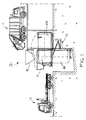
- Figure 1 shows a side view of the transfer station 10 with a waste collecting truck 11 and a transfer truck 12.
- the transfer truck 12 has brought the transport container 20 in a horizontal position to the transfer station.
- the tilting mechanism 13 of the transfer station turns the transport container 20 to a vertical position
- a hopper 14 that works as an intermediate container 20 is brought above the transport container 20 and the hatch 21 of the transport container 20 is opened.
- the waste collecting truck 11 can tip the waste bags through the hopper 14 into the transport container 20.
- This embodiment handles lightweight wastes.
- the hopper 14 may be formed in such a way, that the falling movement of the waste bags is slowed down in the hopper 14. Since the waste bags are relatively light, the bags can be dropped without breaking from the hopper 14 straight to the bottom of the transport container 20.
- the transport container 20 When the transport container 20 is full, the hatch 21 is closed and the transport container 20 is again turned into a horizontal position. After that the transport container 20 is pulled on the transfer truck 12 and transported by the transfer truck 12 to, for instance, a sorting station that is not shown in the figure.
- the hatch 21 of the transport container 20, shown in Figure 1 works as the cover of the container when the transfer container is in a vertical position. At the same time the hatch in the transport container 20 is also the rear door, which is opened when the transport container 20 is tipped for emptying. Since the equipment shown in Figure 1 is meant for lightweight waste bags, the transport container 20 may be filled all the way to the top edge. If needed, the transport container 20 may, however, be equipped with a pressure sensor to determine the weight of the load and to prevent overloading.
- the transfer station 10 of Figure 1 is shown from above. It is provided with six transport containers 20, but with only three hoppers 14.
- every hopper 14 is meant to be used with two transport containers 20 located next to each other. That is why every hopper 14 is attached by a hinge to a point between two hoppers 20a and 20b next to each other. In this way, the hopper 14 can be turned around the hinge 15 above the opening of whichever of the two transport containers 20a or 20b next to each other.
- FIG 3 shows another embodiment of the transfer station 10, that is provided with an intermediate container 17 movable on the guide rails 16 above the transport container 20.
- This intermediate container 17 is most advantageously so large, that the waste collecting truck 11 can, if necessary, empty there the entire load.
- the intermediate container 17 does not, however, become full very easily, since the bottom of the intermediate container is provided with a conveyor belt 18, which during unloading all the time transfers the waste bags forward.
- the waste bags are transferred above the opening of the transport container 20 and dropped into the container. Therefore, the intermediate container 17 does not fill up as long as the conveyor belt 18 is operating.
- the conveyor belt 18 will, however, be stopped in case that the transport container 20, adjacent to intermediate container 17 becomes full. In that case, it is not necessary to interrupt unloading of the waste collecting truck 11, since the entire load fits into the intermediate container 17.
- the intermediate container 17 is moved along the rails 16 of the transverse track above the adjacent empty transport container 20.
- the waste bags in the first, already filled container can be compressed using a compactor 19 located next to the intermediate container 17, in order to get the hatch 21 of the transport container 20 closed.
- Figure 4 shows a side view of the transfer station of Figure 3.
- this embodiment of the transfer station 10 is provided with six transport containers 20 next to each other and with one intermediate container 17.
- the intermediate container 17 is placed on a guide rail 16 of the track above the transport containers 20, the guide rail being so long that the intermediate container 17 can be moved to every transport container 20.
- the rail 16 is even a little longer, so that the waste bags of any of the transport containers 20 can be compressed by one or two compactors 19a and 19b attached to the intermediate container 17.
- On the guide rail 16 of the track there may also be located several intermediate containers 17.
- FIG. 5 shows an embodiment of the transfer station 10, which is intended for heavier waste.
- the waste bags are brought above the opening of the transport container 20 by using two conveyors 24 and 25. Since the waste bags are heavier, they will be dropped against the inner side wall of the transfer container 20, the transfer container 20 being tilted at, for example, the angle of 30° - 40° relative to the vertical position. Hence the falling speed of the falling waste bags is reduced so that the breaking of the waste bags is prevented.
- the tilting angle of the transport container 20 also has another meaning. It controls also the filling of the container.
- the transfer container 20 When the waste bags fall against the side wall of the transfer container 20, the transfer container 20 will be filled along the whole length of its one side. Since concerning heavyweight waste, it is important that the bags to be loaded will be evenly distributed over the whole length of the container. If, instead, the transport container 20 were filled in a vertical position with heavyweight waste bags, the highest allowed weight of the container would easily be achieved before the transfer container 20 was full. Hence, the waste bags accumulated only at the one end of the transport container would burden the front axle of the transfer truck, so that the front axle weight of the transfer truck would exceed the allowed limit.
- the transfer containers can be equipped with pressure sensors.
- the embodiment of the transfer station 10 is provided with a second conveyor 25, which is an extension of the first conveyor, that is transfer conveyor 24, the second conveyor 25 being transverse or perpendicular to the first conveyor 24.
- the second conveyor 25, which works as an intermediate storage for the waste bags, is very close to the opening of the transfer container 20. Hence, the free fall and the falling speed of the waste bags will be as low as possible. Even though the gap between the transfer container 20 and the transverse conveyor 25 is small, the hatch 21 of the transfer container 20 is so constructed that it can still be opened. This is because the opening path of the hatch 21 or the rear door of the transport container 20 is low. In Figure 5 it is presented by a dashed line 26.
- FIG 6 shows the transfer station 10 of Figure 5 seen from above.
- the first transport container 20a is filled first by operating the transverse conveyor 25 into this direction.
- the direction of the transverse conveyor 25 is turned into the opposite direction and the second transfer container 20b will be filled.
- the transport container 20 is also in a tilted position, since also there the heavyweight waste bags are handled.
- the waste bags tipped from the waste collecting truck 11 are first dropped into the hopper 14 and from that further into the transport container 20 against its inner side. These both falling phases are arranged in such a way that the falling speed of the waste bags is minimised.
- the transport container 20 is full, the hopper 14 can be lifted up by turning it around the hinge 15.
- FIG 8 shows a cross-section of a detail of the transfer station 10 in Figure 3.
- a waste collecting truck 11 tips the waste bags 27 into the intermediate container 17, where the conveyor belt 18 at the bottom of the container transfers the waste bags above the opening of the transport container 20.
- This embodiment handles lightweight waste bags, which can be dropped without breaking straight to the bottom of the transfer container 20.
- the intermediate container 17 is necessary, because the breaking of the waste bags 27 could not be prevented if the waste bags were tipped straight into the transfer container 20 from the waste collecting truck 11.
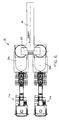
- FIG 9 is presented the mechanism of the hatch 21 or the rear door of the transfer container 20 with the hatch 21 half-open.
- the opening mechanism of the hatch 21 is constructed in such a way, that it requires very little space to open the hatch 21. This goal is achieved by dividing the hatch 21 in two parts 21a and 21b which have been joined together with a hinge 28.
- the hatch 21 is opened with a hydraulic cylinder, whose first end is attached to the frame of the transport container 20 and other end is attached to the supporting arms 30 of the first part 21a of the hatch 21.
- the first part 21 a pushed by the hydraulic cylinder 29, pulls open, by the aid of the hinge 28, also the second part 21b of the hatch 21.
- a support roll 32 which moves along the guide rails 31 at the edge of the opening of the transport container 20.
- This kind of opening mechanism for the hatch 21 needs only very little space to open. Due to the small use of space, the intermediate container 17 for the waste bags can be placed very close to the opening of the transport container 20. Because of this, the free fall of the waste bags to the bottom of the transport container 20 remains as low as possible, which prevents the bags from braking.
Abstract
Description
- The object of the invention is a waste handling method.
- According to a known waste collecting method, wastes are collected from the source with a waste collecting truck and transported to a transfer station. There the waste is transferred into a larger container, i.e. a transfer container, in which the waste is transported to a landfill site for example. The current Waste Management Act, however, requires sorting and recovery of waste, and therefore also the households have to sort different wastes into different waste bags.
- According to a waste collecting system the biological waste of the households is collected into black waste bags and the unsorted municipal waste into white waste bags. However, the same collection truck collects all bags in spite of the colour of the bags. At the transfer station the bags can be sorted or transferred into transfer containers or into transport containers for transporting to a sorting station. The problem in this case, however, is that the bags break easily during these handling procedures. However, they should not break, at least not before they are sorted.
- The purpose of this invention is to create a new waste handling method, which does not have the disadvantages, mentioned above. It is characteristic of the waste handling method according to the invention, that the waste bags are first emptied from the waste collecting truck into an intermediate container, from which the waste bags are transferred into a transfer container or into a transport container.
- In the waste handling method according to the invention, the intermediate container can be placed very close to the outlet hatch of the collecting truck, so that the free fall of the waste bags remains low. It can further be arranged such, that the free fall of the waste bags from the intermediate container to the transport container also remains low. Then the waste bags will not at any phase need to fall from a height and thus the waste bags will better remain intact during all handling phases all the way to the sorting station.
- Another object of the invention is a waste handling equipment. It is characteristic of a waste handling equipment according to the invention that a transfer station is provided with an intermediate container, which is placed between the container that is to be unloaded and the container that is to be loaded. According to an advantageous embodiment of the invention, the intermediate container is located between the waste collecting truck and the transfer truck.
- In the following, the invention is described, using examples, with reference to the accompanying drawings, in which
- Figure 1
- shows a side view of a transfer station according to the invention.
- Figure 2
- shows the transfer station in Figure 1 seen from above.
- Figure 3
- corresponds to Figure 1 and shows the second embodiment of the transfer station.
- Figure 4
- shows the transfer station of Figure 3 seen from the other side.
- Figure 5
- corresponds to Figure 1 and shows the third embodiment of the transfer station.
- Figure 6
- shows the transfer station of Figure 5 seen from above.
- Figure 7
- corresponds to Figure 1 and shows the fourth embodiment of the transfer station.
- Figure 8
- shows a partly cross sectional view of a detail of the transfer station of Figure 3 seen from the side.
- Figure 9
- shows a detail of a transfer container according to the invention.
- Figure 1 shows a side view of the
transfer station 10 with awaste collecting truck 11 and atransfer truck 12. In the situation shown in Figure 1, thetransfer truck 12 has brought thetransport container 20 in a horizontal position to the transfer station. After that, thetilting mechanism 13 of the transfer station turns thetransport container 20 to a vertical position, ahopper 14 that works as anintermediate container 20 is brought above thetransport container 20 and thehatch 21 of thetransport container 20 is opened. Now, thewaste collecting truck 11 can tip the waste bags through thehopper 14 into thetransport container 20. This embodiment handles lightweight wastes. - According to the invention the
hopper 14 may be formed in such a way, that the falling movement of the waste bags is slowed down in thehopper 14. Since the waste bags are relatively light, the bags can be dropped without breaking from thehopper 14 straight to the bottom of thetransport container 20. When thetransport container 20 is full, thehatch 21 is closed and thetransport container 20 is again turned into a horizontal position. After that thetransport container 20 is pulled on thetransfer truck 12 and transported by thetransfer truck 12 to, for instance, a sorting station that is not shown in the figure. - The
hatch 21 of thetransport container 20, shown in Figure 1, works as the cover of the container when the transfer container is in a vertical position. At the same time the hatch in thetransport container 20 is also the rear door, which is opened when thetransport container 20 is tipped for emptying. Since the equipment shown in Figure 1 is meant for lightweight waste bags, thetransport container 20 may be filled all the way to the top edge. If needed, thetransport container 20 may, however, be equipped with a pressure sensor to determine the weight of the load and to prevent overloading. - In Figure 2, the
transfer station 10 of Figure 1 is shown from above. It is provided with sixtransport containers 20, but with only threehoppers 14. In other words, everyhopper 14 is meant to be used with twotransport containers 20 located next to each other. That is why everyhopper 14 is attached by a hinge to a point between twohoppers hopper 14 can be turned around thehinge 15 above the opening of whichever of the twotransport containers - Figure 3 shows another embodiment of the
transfer station 10, that is provided with anintermediate container 17 movable on theguide rails 16 above thetransport container 20. Thisintermediate container 17 is most advantageously so large, that thewaste collecting truck 11 can, if necessary, empty there the entire load. In the normal unloading situation, theintermediate container 17 does not, however, become full very easily, since the bottom of the intermediate container is provided with aconveyor belt 18, which during unloading all the time transfers the waste bags forward. On theconveyor belt 18 the waste bags are transferred above the opening of thetransport container 20 and dropped into the container. Therefore, theintermediate container 17 does not fill up as long as theconveyor belt 18 is operating. - The
conveyor belt 18 will, however, be stopped in case that thetransport container 20, adjacent tointermediate container 17 becomes full. In that case, it is not necessary to interrupt unloading of thewaste collecting truck 11, since the entire load fits into theintermediate container 17. When thewaste collecting truck 11 has been emptied, theintermediate container 17 is moved along therails 16 of the transverse track above the adjacentempty transport container 20. At the time when the second transport container is being filled, the waste bags in the first, already filled container can be compressed using acompactor 19 located next to theintermediate container 17, in order to get thehatch 21 of thetransport container 20 closed. - Figure 4 shows a side view of the transfer station of Figure 3. As seen in the figure, this embodiment of the
transfer station 10 is provided with sixtransport containers 20 next to each other and with oneintermediate container 17. Theintermediate container 17 is placed on aguide rail 16 of the track above thetransport containers 20, the guide rail being so long that theintermediate container 17 can be moved to everytransport container 20. Therail 16 is even a little longer, so that the waste bags of any of thetransport containers 20 can be compressed by one or twocompactors 19a and 19b attached to theintermediate container 17. On theguide rail 16 of the track there may also be located severalintermediate containers 17. - in Figure 4 can be seen that the
wall 22 of theintermediate container 17 is low at the area where the waste bags are tipped from the waste collecting truck into theintermediate container 17. On the other hand theside walls 23 are higher, preventing the tipped waste bags from falling over the side wall at this area. At the bottom of theintermediate container 17 there is seen aconveyor belt 18 that is therefore relatively close to the unloading opening of the waste collecting truck and also close to the inlet opening of theintermediate container 17. The low free fall of the waste bags in both of these transfer phases efficiently prevents the waste bags from breaking. - Figure 5 shows an embodiment of the
transfer station 10, which is intended for heavier waste. There the waste bags are brought above the opening of thetransport container 20 by using twoconveyors transfer container 20, thetransfer container 20 being tilted at, for example, the angle of 30° - 40° relative to the vertical position. Hence the falling speed of the falling waste bags is reduced so that the breaking of the waste bags is prevented. - The tilting angle of the
transport container 20 also has another meaning. It controls also the filling of the container. When the waste bags fall against the side wall of thetransfer container 20, thetransfer container 20 will be filled along the whole length of its one side. Since concerning heavyweight waste, it is important that the bags to be loaded will be evenly distributed over the whole length of the container. If, instead, thetransport container 20 were filled in a vertical position with heavyweight waste bags, the highest allowed weight of the container would easily be achieved before thetransfer container 20 was full. Hence, the waste bags accumulated only at the one end of the transport container would burden the front axle of the transfer truck, so that the front axle weight of the transfer truck would exceed the allowed limit. To prevent overload, the transfer containers can be equipped with pressure sensors. - In Figure 5 the embodiment of the
transfer station 10 is provided with asecond conveyor 25, which is an extension of the first conveyor, that istransfer conveyor 24, thesecond conveyor 25 being transverse or perpendicular to thefirst conveyor 24. Thesecond conveyor 25, which works as an intermediate storage for the waste bags, is very close to the opening of thetransfer container 20. Hence, the free fall and the falling speed of the waste bags will be as low as possible. Even though the gap between thetransfer container 20 and thetransverse conveyor 25 is small, thehatch 21 of thetransfer container 20 is so constructed that it can still be opened. This is because the opening path of thehatch 21 or the rear door of thetransport container 20 is low. In Figure 5 it is presented by a dashedline 26. - Figure 6 shows the
transfer station 10 of Figure 5 seen from above. In this embodiment there are has twotransport containers belt conveyor 24 are transferred by thetransverse conveyor 25. Thefirst transport container 20a is filled first by operating thetransverse conveyor 25 into this direction. When thefirst transport container 20a has become full, the direction of thetransverse conveyor 25 is turned into the opposite direction and thesecond transfer container 20b will be filled. - In the embodiment of the transfer station shown in Figure 7, the
transport container 20 is also in a tilted position, since also there the heavyweight waste bags are handled. The waste bags tipped from thewaste collecting truck 11 are first dropped into thehopper 14 and from that further into thetransport container 20 against its inner side. These both falling phases are arranged in such a way that the falling speed of the waste bags is minimised. When thetransport container 20 is full, thehopper 14 can be lifted up by turning it around thehinge 15. - Figure 8 shows a cross-section of a detail of the
transfer station 10 in Figure 3. In the figure, awaste collecting truck 11 tips thewaste bags 27 into theintermediate container 17, where theconveyor belt 18 at the bottom of the container transfers the waste bags above the opening of thetransport container 20. This embodiment handles lightweight waste bags, which can be dropped without breaking straight to the bottom of thetransfer container 20. In the equipment, however, theintermediate container 17 is necessary, because the breaking of thewaste bags 27 could not be prevented if the waste bags were tipped straight into thetransfer container 20 from thewaste collecting truck 11. - In Figure 9 is presented the mechanism of the
hatch 21 or the rear door of thetransfer container 20 with thehatch 21 half-open. The opening mechanism of thehatch 21 is constructed in such a way, that it requires very little space to open thehatch 21. This goal is achieved by dividing thehatch 21 in twoparts hinge 28. Thehatch 21 is opened with a hydraulic cylinder, whose first end is attached to the frame of thetransport container 20 and other end is attached to the supportingarms 30 of thefirst part 21a of thehatch 21. When opening thehatch 21 thefirst part 21 a, pushed by thehydraulic cylinder 29, pulls open, by the aid of thehinge 28, also thesecond part 21b of thehatch 21. To theopposite edge 21b of the second part of thehatch 21 is attached asupport roll 32, which moves along the guide rails 31 at the edge of the opening of thetransport container 20. This kind of opening mechanism for thehatch 21 needs only very little space to open. Due to the small use of space, theintermediate container 17 for the waste bags can be placed very close to the opening of thetransport container 20. Because of this, the free fall of the waste bags to the bottom of thetransport container 20 remains as low as possible, which prevents the bags from braking.
Claims (10)
- A waste handling method, according to which the wastes (27) are collected at the source by a waste collecting truck (11) or similar and taken to a transfer station (10), where the waste is transferred to a transfer container or to a transport container (20), characterised in that at the transfer station (10) the waste bags (27) are emptied from the waste collecting truck (11) first into an intermediate container (17) or into an intermediate storage (14, 24, 25), from which they are transferred further to a transfer container or to a transport container (20).
- A waste handling method as claimed in claim 1, characterised inthat the transport container (20) is brought by a transfer truck (12) to the transfer station (10) in a horizontal position, after which the tilting mechanism (13) of the transfer station turns the transport container to a vertical position or to a tilted position,that an intermediate container (17) or intermediate storage (14, 24, 25) is brought above the transport container or adjacent to the upper end of the transfer container,that a waste collecting (11) truck tips the waste bags (27), most advantageously filled with lightweight waste, into an intermediate container or into an intermediate storage, from which the waste bags are further transferred to a transport container,and that the hatch (21) of the transport container is closed and the transport container is again turned to a horizontal position, after which the transport container is pulled on a transfer truck (12) and transferred to a sorting station, for example.
- A waste handling method as claimed in claim 1 or 2, characterised in that at the transfer station (10) an intermediate container (17) or an intermediate storage (14, 24, 25) is brought above the transport container (20) or adjacent to the upper end of the transport container to such a position, that the distances from the waste collecting truck (11) to the intermediate container or to the intermediate storage and from there to the transport container are as short as possible.
- A waste handling method as claimed in claim 1, 2 or 3, characterised in that at the transfer station (10) the waste bags (27) are emptied from the waste collecting truck (11) into an intermediate container (17) or into an intermediate storage (14, 24, 25), from which the waste bags are dropped against the tilted side wall of a transfer container or a transport container (20).
- A waste handling method as claimed in any of the claims 1-4, characterised in that the waste bags (27) are emptied from the waste collecting truck (11) against the tilted wall of hopper (14) of the intermediate storage.
- A waste handling equipment, which comprises a transfer station (10), where the wastes (27) are brought from the source by a waste collecting truck (11) or similar, and located at the transfer station a transfer container or transport container (20), where the waste is transferred, characterised in that at the transfer station (10) is provided with an intermediate container (17) or an intermediate storage (14, 24, 25) located between the waste collecting truck (11) or similar and the transfer container or transport container (20), into which intermediate container or intermediate storage the waste bags (27) are emptied from the waste collecting truck (11) or similar.
- A waste handling equipment as claimed in claim 6, characterised in that the intermediate container (17) or the intermediate storage comprises at least one belt conveyor (18, 24, 25).
- A waste handling equipment as claimed in claim 6 or 7, characterised in that on the bottom of the intermediate container (17) there is a conveyor belt (18), for transferring the waste bags (27), tipped into the intermediate container, from the intermediate container further to a transfer container or transport container (20).
- A waste handling equipment as claimed in claim 6 or 7, characterised in that the intermediate storage comprises a transfer belt conveyor (24) and another belt conveyor (25) that is transversely or perpendicularly positioned relative to the transfer belt conveyor.
- A waste handling equipment as claimed in claim 6, characterised in that the intermediate storage is a hopper (14) with tilted side walls.
Applications Claiming Priority (2)
| Application Number | Priority Date | Filing Date | Title |
|---|---|---|---|
| FI20000130 | 2000-01-24 | ||
| FI20000130A FI20000130A0 (en) | 2000-01-24 | 2000-01-24 | Waste treatment method and equipment |
Publications (1)
| Publication Number | Publication Date |
|---|---|
| EP1120364A1 true EP1120364A1 (en) | 2001-08-01 |
Family
ID=8557164
Family Applications (1)
| Application Number | Title | Priority Date | Filing Date |
|---|---|---|---|
| EP01660015A Withdrawn EP1120364A1 (en) | 2000-01-24 | 2001-01-24 | Waste handling method and apparatus |
Country Status (2)
| Country | Link |
|---|---|
| EP (1) | EP1120364A1 (en) |
| FI (1) | FI20000130A0 (en) |
Cited By (3)
| Publication number | Priority date | Publication date | Assignee | Title |
|---|---|---|---|---|
| CN102267615A (en) * | 2011-06-15 | 2011-12-07 | 刘英华 | Compression/storage/exchange boxcar drum-type waste transfer station |
| CN107472773A (en) * | 2017-08-22 | 2017-12-15 | 饶胜智 | A kind of rubbish efficiently fills car |
| CN114194674A (en) * | 2022-02-18 | 2022-03-18 | 徐州徐工环境技术有限公司 | Intensive vertical garbage compression device |
Citations (5)
| Publication number | Priority date | Publication date | Assignee | Title |
|---|---|---|---|---|
| GB1567194A (en) * | 1975-12-17 | 1980-05-14 | Carrier Corp | Method and apparatus for refuse handling |
| DE3537357A1 (en) * | 1984-10-30 | 1986-04-30 | V.I.B. S.r.l., Flero, Brescia | Method for transferring solid municipal wastes from the waste collection containers, especially refuse collection vehicles into box-type semi-trailers, and apparatus for carrying out this method |
| US4832561A (en) * | 1986-04-25 | 1989-05-23 | Hydro Mecanique Research S.A. | Loading system with trash silos |
| WO1997035789A1 (en) * | 1996-03-27 | 1997-10-02 | Recytec Oy | Method for transportation of waste, waste handling system and waste container |
| DE19852416A1 (en) * | 1998-11-13 | 2000-05-18 | Mabeg Ges Fuer Entsorgungsengi | Plant for unloading of refuse from vehicle and transferring it through press to container, has slope conveyor to transfer to intake funnel of press refuse offloaded from vehicle standing at lower level in relation to funnel |
-
2000
- 2000-01-24 FI FI20000130A patent/FI20000130A0/en unknown
-
2001
- 2001-01-24 EP EP01660015A patent/EP1120364A1/en not_active Withdrawn
Patent Citations (5)
| Publication number | Priority date | Publication date | Assignee | Title |
|---|---|---|---|---|
| GB1567194A (en) * | 1975-12-17 | 1980-05-14 | Carrier Corp | Method and apparatus for refuse handling |
| DE3537357A1 (en) * | 1984-10-30 | 1986-04-30 | V.I.B. S.r.l., Flero, Brescia | Method for transferring solid municipal wastes from the waste collection containers, especially refuse collection vehicles into box-type semi-trailers, and apparatus for carrying out this method |
| US4832561A (en) * | 1986-04-25 | 1989-05-23 | Hydro Mecanique Research S.A. | Loading system with trash silos |
| WO1997035789A1 (en) * | 1996-03-27 | 1997-10-02 | Recytec Oy | Method for transportation of waste, waste handling system and waste container |
| DE19852416A1 (en) * | 1998-11-13 | 2000-05-18 | Mabeg Ges Fuer Entsorgungsengi | Plant for unloading of refuse from vehicle and transferring it through press to container, has slope conveyor to transfer to intake funnel of press refuse offloaded from vehicle standing at lower level in relation to funnel |
Cited By (3)
| Publication number | Priority date | Publication date | Assignee | Title |
|---|---|---|---|---|
| CN102267615A (en) * | 2011-06-15 | 2011-12-07 | 刘英华 | Compression/storage/exchange boxcar drum-type waste transfer station |
| CN107472773A (en) * | 2017-08-22 | 2017-12-15 | 饶胜智 | A kind of rubbish efficiently fills car |
| CN114194674A (en) * | 2022-02-18 | 2022-03-18 | 徐州徐工环境技术有限公司 | Intensive vertical garbage compression device |
Also Published As
| Publication number | Publication date |
|---|---|
| FI20000130A0 (en) | 2000-01-24 |
Similar Documents
| Publication | Publication Date | Title |
|---|---|---|
| US6309164B1 (en) | Method and apparatus for collecting recyclable materials | |
| US5288196A (en) | Collecting, hauling and delivering apparatus and method | |
| US5035563A (en) | Waste collection system for segregating solid waste into preselected component materials | |
| CA2129629C (en) | A side-loading refuse vehicle | |
| US9598235B2 (en) | Motor vehicle for collecting and sorting material and method of doing same | |
| US4975019A (en) | Rubbish collecting system | |
| US4425070A (en) | Separated discards carrier | |
| US5511687A (en) | Waste collection and separation system | |
| AU2004200551B2 (en) | Material handling apparatus having a charging hopper and moving floor | |
| US5458452A (en) | Vehicle and method for collecting recyclable waste material | |
| US5252020A (en) | Waste segregating collection apparatus | |
| CA1264702A (en) | Recyclable refuse collecting and transport vehicle with side bucket top loading | |
| US5221173A (en) | Multi-vehicle transport system for bulk materials in confined areas | |
| EP1120364A1 (en) | Waste handling method and apparatus | |
| EP0592530A1 (en) | Collection vehicle for recyclable elements | |
| EP0625118B1 (en) | A side-loading refuse vehicle | |
| JPH041358A (en) | Refuse disposal plant | |
| EP0419423B1 (en) | A railway car for the transportation of debris | |
| WO1994007774A1 (en) | Method and equipment for collecting and transporting refuse | |
| RU2282506C1 (en) | Solid garbage classifying method and complex for performing the same | |
| US20160332814A1 (en) | Waste material processing system having adjacent augers separated by a dividing wall and a recirculation chute | |
| KR200494461Y1 (en) | TRUCK LOADER STRUCTURE for MEDICIAL WASTE | |
| JPH0680202A (en) | Refuse classification and delivery system | |
| EP2412648A1 (en) | A motor-vehicle for rubbish collection | |
| GB2269774A (en) | Can processing plant |
Legal Events
| Date | Code | Title | Description |
|---|---|---|---|
| PUAI | Public reference made under article 153(3) epc to a published international application that has entered the european phase |
Free format text: ORIGINAL CODE: 0009012 |
|
| AK | Designated contracting states |
Kind code of ref document: A1 Designated state(s): AT BE CH CY DE DK ES FI FR GB GR IE IT LI LU MC NL PT SE TR |
|
| AX | Request for extension of the european patent |
Free format text: AL;LT;LV;MK;RO;SI |
|
| 17P | Request for examination filed |
Effective date: 20020201 |
|
| AKX | Designation fees paid |
Free format text: AT BE CH CY DE DK ES FI FR GB GR IE IT LI LU MC NL PT SE TR |
|
| R17P | Request for examination filed (corrected) |
Effective date: 20020201 |
|
| 17Q | First examination report despatched |
Effective date: 20021119 |
|
| STAA | Information on the status of an ep patent application or granted ep patent |
Free format text: STATUS: THE APPLICATION IS DEEMED TO BE WITHDRAWN |
|
| 18D | Application deemed to be withdrawn |
Effective date: 20030531 |