EP1120364A1 - Dispositif et procédé de manutention de déchets - Google Patents
Dispositif et procédé de manutention de déchets Download PDFInfo
- Publication number
- EP1120364A1 EP1120364A1 EP01660015A EP01660015A EP1120364A1 EP 1120364 A1 EP1120364 A1 EP 1120364A1 EP 01660015 A EP01660015 A EP 01660015A EP 01660015 A EP01660015 A EP 01660015A EP 1120364 A1 EP1120364 A1 EP 1120364A1
- Authority
- EP
- European Patent Office
- Prior art keywords
- container
- waste
- transfer
- transport container
- bags
- Prior art date
- Legal status (The legal status is an assumption and is not a legal conclusion. Google has not performed a legal analysis and makes no representation as to the accuracy of the status listed.)
- Withdrawn
Links
Images


Classifications
-
- B—PERFORMING OPERATIONS; TRANSPORTING
- B65—CONVEYING; PACKING; STORING; HANDLING THIN OR FILAMENTARY MATERIAL
- B65F—GATHERING OR REMOVAL OF DOMESTIC OR LIKE REFUSE
- B65F9/00—Transferring of refuse between vehicles or containers with intermediate storage or pressing
Definitions
- the object of the invention is a waste handling method.
- wastes are collected from the source with a waste collecting truck and transported to a transfer station. There the waste is transferred into a larger container, i.e. a transfer container, in which the waste is transported to a landfill site for example.
- a transfer container i.e. a transfer container
- the current Waste Management Act requires sorting and recovery of waste, and therefore also the households have to sort different wastes into different waste bags.
- the biological waste of the households is collected into black waste bags and the unsorted municipal waste into white waste bags.
- the same collection truck collects all bags in spite of the colour of the bags.
- the bags can be sorted or transferred into transfer containers or into transport containers for transporting to a sorting station.
- the problem in this case, however, is that the bags break easily during these handling procedures. However, they should not break, at least not before they are sorted.
- the purpose of this invention is to create a new waste handling method, which does not have the disadvantages, mentioned above. It is characteristic of the waste handling method according to the invention, that the waste bags are first emptied from the waste collecting truck into an intermediate container, from which the waste bags are transferred into a transfer container or into a transport container.
- the intermediate container can be placed very close to the outlet hatch of the collecting truck, so that the free fall of the waste bags remains low. It can further be arranged such, that the free fall of the waste bags from the intermediate container to the transport container also remains low. Then the waste bags will not at any phase need to fall from a height and thus the waste bags will better remain intact during all handling phases all the way to the sorting station.
- Another object of the invention is a waste handling equipment. It is characteristic of a waste handling equipment according to the invention that a transfer station is provided with an intermediate container, which is placed between the container that is to be unloaded and the container that is to be loaded. According to an advantageous embodiment of the invention, the intermediate container is located between the waste collecting truck and the transfer truck.
- Figure 1 shows a side view of the transfer station 10 with a waste collecting truck 11 and a transfer truck 12.
- the transfer truck 12 has brought the transport container 20 in a horizontal position to the transfer station.
- the tilting mechanism 13 of the transfer station turns the transport container 20 to a vertical position
- a hopper 14 that works as an intermediate container 20 is brought above the transport container 20 and the hatch 21 of the transport container 20 is opened.
- the waste collecting truck 11 can tip the waste bags through the hopper 14 into the transport container 20.
- This embodiment handles lightweight wastes.
- the hopper 14 may be formed in such a way, that the falling movement of the waste bags is slowed down in the hopper 14. Since the waste bags are relatively light, the bags can be dropped without breaking from the hopper 14 straight to the bottom of the transport container 20.
- the transport container 20 When the transport container 20 is full, the hatch 21 is closed and the transport container 20 is again turned into a horizontal position. After that the transport container 20 is pulled on the transfer truck 12 and transported by the transfer truck 12 to, for instance, a sorting station that is not shown in the figure.
- the hatch 21 of the transport container 20, shown in Figure 1 works as the cover of the container when the transfer container is in a vertical position. At the same time the hatch in the transport container 20 is also the rear door, which is opened when the transport container 20 is tipped for emptying. Since the equipment shown in Figure 1 is meant for lightweight waste bags, the transport container 20 may be filled all the way to the top edge. If needed, the transport container 20 may, however, be equipped with a pressure sensor to determine the weight of the load and to prevent overloading.
- the transfer station 10 of Figure 1 is shown from above. It is provided with six transport containers 20, but with only three hoppers 14.
- every hopper 14 is meant to be used with two transport containers 20 located next to each other. That is why every hopper 14 is attached by a hinge to a point between two hoppers 20a and 20b next to each other. In this way, the hopper 14 can be turned around the hinge 15 above the opening of whichever of the two transport containers 20a or 20b next to each other.
- FIG 3 shows another embodiment of the transfer station 10, that is provided with an intermediate container 17 movable on the guide rails 16 above the transport container 20.
- This intermediate container 17 is most advantageously so large, that the waste collecting truck 11 can, if necessary, empty there the entire load.
- the intermediate container 17 does not, however, become full very easily, since the bottom of the intermediate container is provided with a conveyor belt 18, which during unloading all the time transfers the waste bags forward.
- the waste bags are transferred above the opening of the transport container 20 and dropped into the container. Therefore, the intermediate container 17 does not fill up as long as the conveyor belt 18 is operating.
- the conveyor belt 18 will, however, be stopped in case that the transport container 20, adjacent to intermediate container 17 becomes full. In that case, it is not necessary to interrupt unloading of the waste collecting truck 11, since the entire load fits into the intermediate container 17.
- the intermediate container 17 is moved along the rails 16 of the transverse track above the adjacent empty transport container 20.
- the waste bags in the first, already filled container can be compressed using a compactor 19 located next to the intermediate container 17, in order to get the hatch 21 of the transport container 20 closed.
- Figure 4 shows a side view of the transfer station of Figure 3.
- this embodiment of the transfer station 10 is provided with six transport containers 20 next to each other and with one intermediate container 17.
- the intermediate container 17 is placed on a guide rail 16 of the track above the transport containers 20, the guide rail being so long that the intermediate container 17 can be moved to every transport container 20.
- the rail 16 is even a little longer, so that the waste bags of any of the transport containers 20 can be compressed by one or two compactors 19a and 19b attached to the intermediate container 17.
- On the guide rail 16 of the track there may also be located several intermediate containers 17.
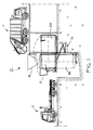
- FIG. 5 shows an embodiment of the transfer station 10, which is intended for heavier waste.
- the waste bags are brought above the opening of the transport container 20 by using two conveyors 24 and 25. Since the waste bags are heavier, they will be dropped against the inner side wall of the transfer container 20, the transfer container 20 being tilted at, for example, the angle of 30° - 40° relative to the vertical position. Hence the falling speed of the falling waste bags is reduced so that the breaking of the waste bags is prevented.
- the tilting angle of the transport container 20 also has another meaning. It controls also the filling of the container.
- the transfer container 20 When the waste bags fall against the side wall of the transfer container 20, the transfer container 20 will be filled along the whole length of its one side. Since concerning heavyweight waste, it is important that the bags to be loaded will be evenly distributed over the whole length of the container. If, instead, the transport container 20 were filled in a vertical position with heavyweight waste bags, the highest allowed weight of the container would easily be achieved before the transfer container 20 was full. Hence, the waste bags accumulated only at the one end of the transport container would burden the front axle of the transfer truck, so that the front axle weight of the transfer truck would exceed the allowed limit.
- the transfer containers can be equipped with pressure sensors.
- the embodiment of the transfer station 10 is provided with a second conveyor 25, which is an extension of the first conveyor, that is transfer conveyor 24, the second conveyor 25 being transverse or perpendicular to the first conveyor 24.
- the second conveyor 25, which works as an intermediate storage for the waste bags, is very close to the opening of the transfer container 20. Hence, the free fall and the falling speed of the waste bags will be as low as possible. Even though the gap between the transfer container 20 and the transverse conveyor 25 is small, the hatch 21 of the transfer container 20 is so constructed that it can still be opened. This is because the opening path of the hatch 21 or the rear door of the transport container 20 is low. In Figure 5 it is presented by a dashed line 26.
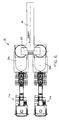
- FIG 6 shows the transfer station 10 of Figure 5 seen from above.
- the first transport container 20a is filled first by operating the transverse conveyor 25 into this direction.
- the direction of the transverse conveyor 25 is turned into the opposite direction and the second transfer container 20b will be filled.
- the transport container 20 is also in a tilted position, since also there the heavyweight waste bags are handled.
- the waste bags tipped from the waste collecting truck 11 are first dropped into the hopper 14 and from that further into the transport container 20 against its inner side. These both falling phases are arranged in such a way that the falling speed of the waste bags is minimised.
- the transport container 20 is full, the hopper 14 can be lifted up by turning it around the hinge 15.
- FIG 8 shows a cross-section of a detail of the transfer station 10 in Figure 3.
- a waste collecting truck 11 tips the waste bags 27 into the intermediate container 17, where the conveyor belt 18 at the bottom of the container transfers the waste bags above the opening of the transport container 20.
- This embodiment handles lightweight waste bags, which can be dropped without breaking straight to the bottom of the transfer container 20.
- the intermediate container 17 is necessary, because the breaking of the waste bags 27 could not be prevented if the waste bags were tipped straight into the transfer container 20 from the waste collecting truck 11.
- FIG 9 is presented the mechanism of the hatch 21 or the rear door of the transfer container 20 with the hatch 21 half-open.
- the opening mechanism of the hatch 21 is constructed in such a way, that it requires very little space to open the hatch 21. This goal is achieved by dividing the hatch 21 in two parts 21a and 21b which have been joined together with a hinge 28.
- the hatch 21 is opened with a hydraulic cylinder, whose first end is attached to the frame of the transport container 20 and other end is attached to the supporting arms 30 of the first part 21a of the hatch 21.
- the first part 21 a pushed by the hydraulic cylinder 29, pulls open, by the aid of the hinge 28, also the second part 21b of the hatch 21.
- a support roll 32 which moves along the guide rails 31 at the edge of the opening of the transport container 20.
- This kind of opening mechanism for the hatch 21 needs only very little space to open. Due to the small use of space, the intermediate container 17 for the waste bags can be placed very close to the opening of the transport container 20. Because of this, the free fall of the waste bags to the bottom of the transport container 20 remains as low as possible, which prevents the bags from braking.
Applications Claiming Priority (2)
| Application Number | Priority Date | Filing Date | Title |
|---|---|---|---|
| FI20000130A FI20000130A0 (fi) | 2000-01-24 | 2000-01-24 | Jättenkäsittelymenetelmä ja -laitteisto |
| FI20000130 | 2000-01-24 |
Publications (1)
| Publication Number | Publication Date |
|---|---|
| EP1120364A1 true EP1120364A1 (fr) | 2001-08-01 |
Family
ID=8557164
Family Applications (1)
| Application Number | Title | Priority Date | Filing Date |
|---|---|---|---|
| EP01660015A Withdrawn EP1120364A1 (fr) | 2000-01-24 | 2001-01-24 | Dispositif et procédé de manutention de déchets |
Country Status (2)
| Country | Link |
|---|---|
| EP (1) | EP1120364A1 (fr) |
| FI (1) | FI20000130A0 (fr) |
Cited By (3)
| Publication number | Priority date | Publication date | Assignee | Title |
|---|---|---|---|---|
| CN102267615A (zh) * | 2011-06-15 | 2011-12-07 | 刘英华 | 压缩、贮存、交换卡车车厢筒式垃圾中转站 |
| CN107472773A (zh) * | 2017-08-22 | 2017-12-15 | 饶胜智 | 一种垃圾高效填埋车 |
| CN114194674A (zh) * | 2022-02-18 | 2022-03-18 | 徐州徐工环境技术有限公司 | 一种集约型竖直压缩垃圾装置 |
Citations (5)
| Publication number | Priority date | Publication date | Assignee | Title |
|---|---|---|---|---|
| GB1567194A (en) * | 1975-12-17 | 1980-05-14 | Carrier Corp | Method and apparatus for refuse handling |
| DE3537357A1 (de) * | 1984-10-30 | 1986-04-30 | V.I.B. S.r.l., Flero, Brescia | Verfahren zum umfuellen von festen urbanen abfaellen aus den abfall-sammelbehaeltern, insbesondere muellsammelfahrzeugen, in kastenartige sattelzugauflieger und vorrichtung zur durchfuehrung dieses verfahrens |
| US4832561A (en) * | 1986-04-25 | 1989-05-23 | Hydro Mecanique Research S.A. | Loading system with trash silos |
| WO1997035789A1 (fr) * | 1996-03-27 | 1997-10-02 | Recytec Oy | Procede de transport des ordures, systeme de manipulation d'ordures et conteneur a ordures |
| DE19852416A1 (de) * | 1998-11-13 | 2000-05-18 | Mabeg Ges Fuer Entsorgungsengi | Anlage zum Umladen von Müll aus Müllfahrzeugen über eine Müllpresse in Container |
-
2000
- 2000-01-24 FI FI20000130A patent/FI20000130A0/fi unknown
-
2001
- 2001-01-24 EP EP01660015A patent/EP1120364A1/fr not_active Withdrawn
Patent Citations (5)
| Publication number | Priority date | Publication date | Assignee | Title |
|---|---|---|---|---|
| GB1567194A (en) * | 1975-12-17 | 1980-05-14 | Carrier Corp | Method and apparatus for refuse handling |
| DE3537357A1 (de) * | 1984-10-30 | 1986-04-30 | V.I.B. S.r.l., Flero, Brescia | Verfahren zum umfuellen von festen urbanen abfaellen aus den abfall-sammelbehaeltern, insbesondere muellsammelfahrzeugen, in kastenartige sattelzugauflieger und vorrichtung zur durchfuehrung dieses verfahrens |
| US4832561A (en) * | 1986-04-25 | 1989-05-23 | Hydro Mecanique Research S.A. | Loading system with trash silos |
| WO1997035789A1 (fr) * | 1996-03-27 | 1997-10-02 | Recytec Oy | Procede de transport des ordures, systeme de manipulation d'ordures et conteneur a ordures |
| DE19852416A1 (de) * | 1998-11-13 | 2000-05-18 | Mabeg Ges Fuer Entsorgungsengi | Anlage zum Umladen von Müll aus Müllfahrzeugen über eine Müllpresse in Container |
Cited By (3)
| Publication number | Priority date | Publication date | Assignee | Title |
|---|---|---|---|---|
| CN102267615A (zh) * | 2011-06-15 | 2011-12-07 | 刘英华 | 压缩、贮存、交换卡车车厢筒式垃圾中转站 |
| CN107472773A (zh) * | 2017-08-22 | 2017-12-15 | 饶胜智 | 一种垃圾高效填埋车 |
| CN114194674A (zh) * | 2022-02-18 | 2022-03-18 | 徐州徐工环境技术有限公司 | 一种集约型竖直压缩垃圾装置 |
Also Published As
| Publication number | Publication date |
|---|---|
| FI20000130A0 (fi) | 2000-01-24 |
Similar Documents
| Publication | Publication Date | Title |
|---|---|---|
| US6309164B1 (en) | Method and apparatus for collecting recyclable materials | |
| US5288196A (en) | Collecting, hauling and delivering apparatus and method | |
| US5035563A (en) | Waste collection system for segregating solid waste into preselected component materials | |
| CA2129629C (fr) | Camion collecteur de dechets a chargement lateral | |
| US9598235B2 (en) | Motor vehicle for collecting and sorting material and method of doing same | |
| US4975019A (en) | Rubbish collecting system | |
| US4425070A (en) | Separated discards carrier | |
| US5511687A (en) | Waste collection and separation system | |
| AU2004200551B2 (en) | Material handling apparatus having a charging hopper and moving floor | |
| US5458452A (en) | Vehicle and method for collecting recyclable waste material | |
| US5252020A (en) | Waste segregating collection apparatus | |
| CA1264702A (fr) | Vehicule de ramassage et de transport de dechets recyclables, a chargement par le sommet du recipient lateral | |
| US5221173A (en) | Multi-vehicle transport system for bulk materials in confined areas | |
| EP1120364A1 (fr) | Dispositif et procédé de manutention de déchets | |
| EP0592530A1 (fr) | Vehicule de ramassage d'elements recyclables | |
| EP0625118B1 (fr) | Vehicule de collecte d'ordures a chargement lateral | |
| JPH041358A (ja) | 塵芥処理装置 | |
| WO1994007774A1 (fr) | Procede et appareil utilises pour collecter et transporter des detritus | |
| EP0419423A1 (fr) | Véhicule ferroviaire pour le transport des pravats | |
| RU2282506C1 (ru) | Способ сортировки твердых отходов и комплекс для его осуществления | |
| US20160332814A1 (en) | Waste material processing system having adjacent augers separated by a dividing wall and a recirculation chute | |
| KR200494461Y1 (ko) | 의료폐기물 트럭 적재함 장치 | |
| JPH0680202A (ja) | ごみ仕分け搬出システム | |
| EP2412648A1 (fr) | Véhicule de ramassage d'ordures | |
| GB2269774A (en) | Can processing plant |
Legal Events
| Date | Code | Title | Description |
|---|---|---|---|
| PUAI | Public reference made under article 153(3) epc to a published international application that has entered the european phase |
Free format text: ORIGINAL CODE: 0009012 |
|
| AK | Designated contracting states |
Kind code of ref document: A1 Designated state(s): AT BE CH CY DE DK ES FI FR GB GR IE IT LI LU MC NL PT SE TR |
|
| AX | Request for extension of the european patent |
Free format text: AL;LT;LV;MK;RO;SI |
|
| 17P | Request for examination filed |
Effective date: 20020201 |
|
| AKX | Designation fees paid |
Free format text: AT BE CH CY DE DK ES FI FR GB GR IE IT LI LU MC NL PT SE TR |
|
| R17P | Request for examination filed (corrected) |
Effective date: 20020201 |
|
| 17Q | First examination report despatched |
Effective date: 20021119 |
|
| STAA | Information on the status of an ep patent application or granted ep patent |
Free format text: STATUS: THE APPLICATION IS DEEMED TO BE WITHDRAWN |
|
| 18D | Application deemed to be withdrawn |
Effective date: 20030531 |