EP1120322A2 - Drehscheibe - Google Patents
Drehscheibe Download PDFInfo
- Publication number
- EP1120322A2 EP1120322A2 EP01101416A EP01101416A EP1120322A2 EP 1120322 A2 EP1120322 A2 EP 1120322A2 EP 01101416 A EP01101416 A EP 01101416A EP 01101416 A EP01101416 A EP 01101416A EP 1120322 A2 EP1120322 A2 EP 1120322A2
- Authority
- EP
- European Patent Office
- Prior art keywords
- turntable
- substructure
- support
- turntable according
- tread
- Prior art date
- Legal status (The legal status is an assumption and is not a legal conclusion. Google has not performed a legal analysis and makes no representation as to the accuracy of the status listed.)
- Withdrawn
Links
- 238000010276 construction Methods 0.000 claims abstract description 14
- 241000239290 Araneae Species 0.000 claims abstract description 3
- 230000005611 electricity Effects 0.000 claims description 4
- 239000007788 liquid Substances 0.000 claims description 4
- 238000003825 pressing Methods 0.000 claims description 4
- 238000004519 manufacturing process Methods 0.000 description 3
- 239000000463 material Substances 0.000 description 3
- 239000002184 metal Substances 0.000 description 3
- 229910000831 Steel Inorganic materials 0.000 description 2
- 239000000853 adhesive Substances 0.000 description 2
- 238000004026 adhesive bonding Methods 0.000 description 2
- 230000001070 adhesive effect Effects 0.000 description 2
- 238000005096 rolling process Methods 0.000 description 2
- 239000010959 steel Substances 0.000 description 2
- 239000002023 wood Substances 0.000 description 2
- OKTJSMMVPCPJKN-UHFFFAOYSA-N Carbon Chemical compound [C] OKTJSMMVPCPJKN-UHFFFAOYSA-N 0.000 description 1
- 240000003085 Quassia amara Species 0.000 description 1
- 240000000528 Ricinus communis Species 0.000 description 1
- 235000004443 Ricinus communis Nutrition 0.000 description 1
- 230000004308 accommodation Effects 0.000 description 1
- 230000000903 blocking effect Effects 0.000 description 1
- 229910052799 carbon Inorganic materials 0.000 description 1
- 239000004918 carbon fiber reinforced polymer Substances 0.000 description 1
- 238000011109 contamination Methods 0.000 description 1
- 239000011152 fibreglass Substances 0.000 description 1
- 238000009434 installation Methods 0.000 description 1
- 238000012423 maintenance Methods 0.000 description 1
- 230000008439 repair process Effects 0.000 description 1
- 229910000859 α-Fe Inorganic materials 0.000 description 1
Images




Classifications
-
- B—PERFORMING OPERATIONS; TRANSPORTING
- B60—VEHICLES IN GENERAL
- B60S—SERVICING, CLEANING, REPAIRING, SUPPORTING, LIFTING, OR MANOEUVRING OF VEHICLES, NOT OTHERWISE PROVIDED FOR
- B60S13/00—Vehicle-manoeuvring devices separate from the vehicle
- B60S13/02—Turntables; Traversers
-
- E—FIXED CONSTRUCTIONS
- E04—BUILDING
- E04H—BUILDINGS OR LIKE STRUCTURES FOR PARTICULAR PURPOSES; SWIMMING OR SPLASH BATHS OR POOLS; MASTS; FENCING; TENTS OR CANOPIES, IN GENERAL
- E04H6/00—Buildings for parking cars, rolling-stock, aircraft, vessels or like vehicles, e.g. garages
- E04H6/08—Garages for many vehicles
- E04H6/12—Garages for many vehicles with mechanical means for shifting or lifting vehicles
- E04H6/30—Garages for many vehicles with mechanical means for shifting or lifting vehicles with means for transport in horizontal direction only
- E04H6/40—Garages for many vehicles with mechanical means for shifting or lifting vehicles with means for transport in horizontal direction only characterised by use of turntables or rotary rings
Definitions
- the invention relates to a turntable for various purposes, e.g. For EMC measuring laboratories, presentations of products and vehicles and the like, according to those specified in the preamble of the independent claim Characteristics.
- turntables There are turntables, turntables, turning devices etc. for various Purposes known with various design features.
- WO-A-98/30424 a turntable for vehicles which has a base plate and one with respect to this rotatable cover plate, the cover plate centrally and mounted on the base plate via support bearings arranged on the outer circumference is.
- the plates and the bearings are made of steel. It means that Plates of larger diameter are very difficult and difficult to transport are.
- this known construction has a relatively large overall height, which is disadvantageous for certain purposes.
- the object of the present invention is to make a turntable known Art in such a way that they have a low profile and a relative to Size has low weight. Furthermore, the construction should be simple in manufacturing and easy to transport.
- the invention is characterized in that the turntable as multilayer, deformation-resistant sandwich construction is formed and the load-bearing and Drive elements recessed and / or nested in the substructure are included.
- the middle layer of the sandwich structure consists of light Material, e.g. B. wood, and is covered with top layers of z. B. steel by gluing and / or screwed together.
- the individual parts can be cost-effectively with manufacture any geometries on CNC processing machines. It follows thus a stable, flat construction.
- the rigid Sandwich construction enables high loads. Also applying brittle, brittle surfaces, e.g. B. tiles, sintered ferrite is favored. Through the flat design of the turntable there is the possibility of arranging Carrier roller circles on any diameter.
- the turntable Due to the nested arrangement of the support and drive elements and that Sinking these elements into the substructure becomes an extremely flat one Design of the turntable enables the loss amount in significantly reduced to the thickness of the turntable. By the low achieved
- the turntable can be installed on site without structural adjustments, e.g. in a Pit or drive recess, be set up and z. B. about a small one Be driven on ramp. Unevenness in the floor space can be caused by Adjusting screws can be compensated.
- the substructure consists of a flat, one-piece disk and is preferably designed as a deformation-resistant sandwich construction.
- the substructure is preferably constructed in the manner of a spider's web and comprises concentrically arranged circular ring segments which are connected to one another via radially extending strips.
- the substructure is used for nested mounting of the support and drive elements on different diameters and has recesses and rotating unions for electricity, liquid or other media.
- the support and drive elements are preferably fixed in the substructure via plug-in bearings, which enables quick, tool-free installation.
- the turntable is composed of individual circular sections.
- the circular sections are advantageously connected to one another in a fixed but detachable manner by a special connecting system, two adjacent circular sections each being connected to one another in a form-fitting and rigid manner by a threaded strip and two connecting strips which can be connected to the threaded strip.
- the turntable is preferably in the center via a ball swivel connection on the Supported substructure.
- the ball slewing ring is used for centric Guide of the turntable, for taking up the vertical load, as well as for taking of the load torque if additional idlers are not used.
- Ball slewing rings can also be around the center in the substructure used idlers and additional radial guide rollers can be provided.
- the turntable preferably has one in the area of the ball slewing ring central opening for the passage of electricity as well as liquid or gaseous Media on. This is an accommodation for rotary unions for any Media possible.
- the flat turntable is also with lockable cutouts for Rotating unions and for access to the support and drive elements Mistake.
- the drive element consists of at least one driven on the underside of the turntable Friction wheel, which can be adjusted by a pressure device with adjustable force Turntable is pressed.
- a pressure device with adjustable force Turntable is pressed.
- the support elements consist of at least two Idlers, one idler a relatively soft and the other idler has relatively hard tread, and the tread of the soft idler over the tread of the hard idler protrudes.
- Another embodiment provides that the support elements from one Carrier roller with a relatively hard tread, being in the tread Rubber ring of lower hardness is incorporated, which protrudes over the tread.
- the pairing of hard and soft treads or castors has the advantage that due to the deformation of the soft roller, the hard roller only with larger ones Editing forces come into play. As a result, the turntable runs at low Loads on the soft idlers are relatively quiet.
- the idlers and the drive wheel are rolled on the underside of the turntable, the risk of contamination and blocking by obstacles is reduced, in contrast to the reverse arrangement with the rollers on the turntable.
- the rolling and the drive take place on a suitable, flat running surface of the turntable.
- the idlers are inserted into the substructure and roll tangentially on one or more circles concentric to the pivot point of the turntable.
- the idlers are fixed in the substructure using plug-in bearings without a screw connection.
- the substructure has set screws, due to the unevenness the footprint can be compensated.
- threads e.g. Drive-in nuts are used.
- FIGS 1 and 2 show the basic structure of the invention Turntable.
- the turntable essentially comprises a substructure 1, which consist of concentrically arranged circular ring segments 2, 3 exists, which are connected to one another via radially extending strips 4 are.
- the circular ring segments 2, 3 lie on the bottom surface 5.
- a turntable 6 is now rotatably arranged above the substructure 1, which in the present exemplary embodiment from a multiplicity of circular sections 7 is composed.
- the turntable is on the one hand in its center by means of e.g. a ball bearing 8 on the substructure 1 and on the other hand via idlers 11, which are distributed on the substructure in corresponding recesses 10 are arranged.
- the idlers 11 and the Drive elements described below are in the substructure sunk and / or nested, so that the loss in the substantially reduced to the thickness of the turntable 6.
- the central rotary connection 8 and also the turntable 6 have a central one Implementation 9 on which to carry electricity and liquid or serves gaseous media.
- Figure 3 shows a section through the turntable 6, which consists of a there is an essential three-layer sandwich construction.
- the turntable 6 comprises a central layer made of wood-based material 14, which is above and below each with a top layer of sheet metal 12 or carbon or glass fiber reinforced plastic by gluing and / or screwing connected is.
- the layers are preferred via an adhesive connection 13 glued together.
- a special connection system is provided. This includes a medium one Threaded strip 18, which each with positive and top Connection strips 17 is covered. At the edge of the sectors 7a, 7b Sheet metal covering 12 each has a depression 15, 16 into which a Countersunk screw 19 engages and the connecting strips 17 firmly with the Threaded strip 18 connects. This creates between the neighboring ones Circular sections 7a and 7b a stable and rigid connection.
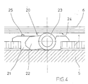
- Figure 4 shows a possible embodiment of the drive unit for the turntable.
- the bottom surface 5 on which the substructure 1 can be seen can again be seen stores over which the turntable 6 is arranged.
- the substructure has a recess in which the holder 21 for the drive unit is arranged.
- a movable Pressure device 22 arranged, which is a motor-driven friction wheel 23 carries, which by the pressing device on the underside of the turntable 6 is pressed.
- the turntable 6 has a bottom on it corresponding tread 24. With an adjusting screw 25, the Pressing force of the friction wheel can be adjusted.
- the drive device 20 is both electromotive can also work hydraulically or pneumatically.
- FIGS 5 and 6 show two possible configurations of the support elements.
- Figure 5 shows a support element consisting of three support rollers 28, 30 which are rotatably mounted on a common axis 27 independently of one another via ball bearings 29, 31 or the like.
- the middle roller 30 has a relatively soft tread and is slightly larger in diameter than the two outer rollers 28, which are equipped with a harder tread.
- the turntable 6 is mounted on top of the rollers, the load being low Turntable 6 only the tread of the middle roller 30 with the bottom of the Turntable 6 comes into contact.
- the soft roller 30 deforms and the turntable 6 gradually comes in Contact with the treads of the harder wheels 28. This has the advantage that at low load also low running noises occur because the soft roller the Dampens running noise well.
- FIG. 6 Another embodiment is shown in FIG. 6, with only one as the supporting element Roller 32 is used, initially with a relatively hard tread Is provided. However, the roller 32 is relative on its tread soft rubber ring 33 or the like provided, with low load of the turntable 6 this only comes into contact with the rubber ring 33, which the Reduces running noise. The greater the load on the turntable 6, the more becomes stronger the rubber ring 33 is compressed, so that ultimately the entire running surface of the roller 32 comes into contact with the turntable 6.
- FIGS. 7 and 8 show a configuration similar to that of the figures 1 and 2, but between the turntable 6 and the substructure 1 Threaded spindles 35 can be used, through which individual or all Sectors of the turntable can be raised by a certain height 36, as particularly shown on the right in FIG. 7.
Landscapes
- Engineering & Computer Science (AREA)
- Architecture (AREA)
- Mechanical Engineering (AREA)
- Civil Engineering (AREA)
- Structural Engineering (AREA)
- Vehicle Cleaning, Maintenance, Repair, Refitting, And Outriggers (AREA)
- Holding Or Fastening Of Disk On Rotational Shaft (AREA)
Abstract
Description
Bei größeren Drehscheiben ist die Unterkonstruktion bevorzugt spinnennetzartig aufgebaut und umfasst konzentrisch angeordnete Kreisringsegmente, die über radial verlaufende Leisten miteinander verbunden sind.
Die Unterkonstruktion dient zur verschachtelten Aufnahme der Trag- und Antriebselemente auf unterschiedlichen Durchmessern und weist hierfür Ausnehmungen und Drehdurchführungen für Strom, flüssige oder sonstige Medien auf.
Dabei werden die Trag- und Antriebselemente bevorzugt über Stecklager in der Unterkonstruktion fixiert, was eine schnelle werkzeuglose Montage ermöglicht.
De Kreisausschnitte werden vorteilhaft durch ein spezielles Verbindungssystem fest aber lösbar miteinander verbunden, wobei jeweils zwei benachbarte Kreisausschnitte durch jeweils eine Gewindeleiste und zwei mit der Gewindeleiste verbindbare Verbindungsleisten formschlüssig und biegesteif miteinander verbunden sind.
Durch die Aufteilung des Drehtellers in einzelne Kreisausschnitte und die biegesteife Verbindung der Einzelteile von Drehteller und Unterkonstruktion sind nahezu beliebige Größen der Drehscheibe realisierbar.
Die Tragrollen sind in die Unterkonstruktion eingesetzt, und rollen auf einem oder mehreren zum Drehpunkt des Drehtellers konzentrischen Kreisen tangential ab. Die Tragrollen werden über Stecklager ohne Schraubverbindung in der Unterkonstruktion fixiert.
- Figur 1:
- einen seitlichen Schnitt durch die erfindungsgemäße Drehscheibe;
- Figur 2:
- eine Draufsicht auf die erfindungsgemäße Drehscheibe mit teilweise dargestelltem Drehteller;
- Figur 3:
- einen Schnitt durch den Drehteller, bei welchem der sandwichartige Aufbau des Drehtellers mit Verbindungssystem erkennbar ist;
- Figur 4:
- einen Schnitt durch die Drehscheibe im Bereich der Antriebsvorrichtung;
- Figur 5:
- eine erste Ausführungsform eines Tragelementes mit unterschiedlich harten Tragrollen;
- Figur 6:
- eine weitere Ausführungsform eines Tragelementes mit speziell ausgestalteter Tragrolle;
- Figur 7:
- einen Schnitt durch die erfindungsgemäße Drehscheibe, ähnlich wie in Figur 1 mit einem angehobenen Kreisausschnitt;
- Figur 8:
- eine Draufsicht auf die Anordnung gemäß Figur 7.
Die mittlere Rolle 30 weist einen relativ weichen Laufbelag auf und ist im Durchmesser etwas größer als die beiden äußeren Rollen 28, die mit einer härteren Lauffläche ausgestattet sind.
- 1
- Unterkonstruktion
- 2
- Kreisringsegment
- 3
- Kreisringsegment
- 4
- Leiste
- 5
- Bodenfläche
- 6
- Drehteller
- 7
- Kreisausschnitt
- 8
- Drehverbindung
- 9
- Durchführung
- 10
- Ausnehmung
- 11
- Tragrolle
- 12
- Blechbelag
- 13
- Klebeverbindung
- 14
- Holzwerkstoff
- 15
- Senkung (Sektor 1)
- 16
- Senkung (Sektor 2)
- 17
- Verbindungsleiste
- 18
- Gewindeleiste
- 19
- Senkschraube
- 20
- Antrieb
- 21
- Halterung
- 22
- Andrückvorrichtung
- 23
- Reibrad
- 24
- Lauffläche
- 25
- Einstellschraube
- 26
- Tragelement
- 27
- Achse
- 28
- Rolle
- 29
- Lager
- 30
- Rolle
- 31
- Lager
- 32
- Tragrolle
- 33
- Gummiring
- 34
- Lager
- 35
- Gewindespindel
- 36
- Hub
Claims (12)
- Drehscheibe mit einer Unterkonstruktion und einem auf der Unterkonstruktion mittels Trag- und Antriebselementen drehbar gelagerten Drehteller,
dadurch gekennzeichnet,dass der Drehteller (6) als mehrlagige, verformungssteife Sandwichkonstruktion ausgebildet ist,und die Trag- und Antriebselemente (11, 20) versenkt und/oder verschachtelt in der Unterkonstruktion (1) aufgenommen sind. - Drehscheibe nach Anspruch 1, dadurch gekennzeichnet, dass die Unterkonstruktion (1) spinnennetzartig aufgebaut ist und konzentrisch angeordnete Kreisringsegmente (2,3) umfasst, die über radial verlaufende Leisten (4) miteinander verbunden sind.
- Drehscheibe nach Anspruch 1 oder 2, dadurch gekennzeichnet, dass die Unterkonstruktion (1) Ausnehmungen (10) zur versenkten und/oder verschachtelten Aufnahme der Trag- und Antriebselemente (11,20) aufweist.
- Drehscheibe nach einem der Ansprüche 1 bis 3, dadurch gekennzeichnet, dass die Trag- und Antriebselemente (11,20) über Stecklager in der Unterkonstruktion (1) fixierbar sind.
- Drehscheibe nach einem der Ansprüche 1 bis 4, dadurch gekennzeichnet, dass der Drehteller (6) aus einzelnen Kreisausschnitten (7) zusammengesetzt ist.
- Drehscheibe nach einem der Ansprüche 1 bis 5, dadurch gekennzeichnet, dass die Kreisausschnitte (7) durch ein lösbares Verbindungssystem fest miteinander verbunden sind, wobei jeweils zwei benachbarte Kreisausschnitte durch jeweils eine Gewindeleiste (18) und zwei mit der Gewindeleiste verbindbare Verbindungsleisten (17) formschlüssig und biegesteif miteinander verbunden sind.
- Drehscheibe nach einem der Ansprüche 1 bis 6, dadurch gekennzeichnet, dass der Drehteller (6) im Zentrum über eine Kugeldrehverbindung (8) auf der Unterkonstruktion (1) gelagert ist.
- Drehscheibe nach einem der Ansprüche 1 bis 7, dadurch gekennzeichnet, dass der Drehteller (6) im Bereich der Kugeldrehverbindung (8) eine zentrale Öffnung (9) zur Durchführung von Strom sowie flüssigen oder gasförmigen Medien aufweist.
- Drehscheibe nach einem der Ansprüche 1 bis 8, dadurch gekennzeichnet, dass im Drehteller (6) Stellgewinde vorgesehen sind, in welchen Gewindespindeln (35) aufgenommen sind, die ein individuelles Anheben eines oder mehrerer Kreisausschnitte (7) des Drehtellers gegenüber der Unterkonstruktion (1) erlauben.
- Drehscheibe nach einem der Ansprüche 1 bis 9, dadurch gekennzeichnet, dass das Antriebselement (20) aus mindestens einem auf die Unterseite des Drehtellers abrollenden, angetriebenen Reibrad (23) besteht, welches durch eine Andrückvorrichtung (22) mit einstellbarer Kraft an den Drehteller (6) gepresst wird.
- Drehscheibe nach einem der Ansprüche 1 bis 10, dadurch gekennzeichnet, dass die Tragelemente (26) aus mindestens zwei Tragrollen (28, 30) besteht, wobei eine Tragrolle (30) eine relativ weiche und die andere Tragrolle (28) eine relativ harte Lauffläche aufweist, und die Lauffläche der weichen Tragrolle über die Lauffläche der harten Tragrolle hervorsteht.
- Drehscheibe nach einem der Ansprüche 1 bis 10, dadurch gekennzeichnet, dass die Tragelemente aus einer Tragrolle (32) mit einer relativ harten Lauffläche besteht, wobei in der Lauffläche ein Gummiring (33) geringerer Härte eingearbeitet ist, der über die Lauffläche hervorsteht.
Applications Claiming Priority (2)
| Application Number | Priority Date | Filing Date | Title |
|---|---|---|---|
| DE2000103413 DE10003413A1 (de) | 2000-01-27 | 2000-01-27 | Drehscheibe |
| DE10003413 | 2000-01-27 |
Publications (2)
| Publication Number | Publication Date |
|---|---|
| EP1120322A2 true EP1120322A2 (de) | 2001-08-01 |
| EP1120322A3 EP1120322A3 (de) | 2003-10-08 |
Family
ID=7628842
Family Applications (1)
| Application Number | Title | Priority Date | Filing Date |
|---|---|---|---|
| EP01101416A Withdrawn EP1120322A3 (de) | 2000-01-27 | 2001-01-23 | Drehscheibe |
Country Status (2)
| Country | Link |
|---|---|
| EP (1) | EP1120322A3 (de) |
| DE (1) | DE10003413A1 (de) |
Families Citing this family (1)
| Publication number | Priority date | Publication date | Assignee | Title |
|---|---|---|---|---|
| WO2017209702A1 (en) * | 2016-05-31 | 2017-12-07 | Banchongsiricharoen Prapat | Car u-turn platform |
Citations (1)
| Publication number | Priority date | Publication date | Assignee | Title |
|---|---|---|---|---|
| WO1998030424A1 (en) | 1997-01-07 | 1998-07-16 | Jontan Industries Pty. Ltd. | Vehicle turntable |
Family Cites Families (12)
| Publication number | Priority date | Publication date | Assignee | Title |
|---|---|---|---|---|
| US51192A (en) * | 1865-11-28 | Improved railroad turn-table | ||
| US563480A (en) * | 1896-07-07 | Reenleaf | ||
| GB325182A (en) * | 1929-06-05 | 1930-02-13 | Ernest Hill Aldam | A new or improved turntable for road vehicles |
| US1977864A (en) * | 1931-05-18 | 1934-10-23 | George A Smith Turntable Corp | Vehicle turntable |
| US1969634A (en) * | 1932-04-25 | 1934-08-07 | James D Acuff | Turntable |
| US2244598A (en) * | 1940-05-23 | 1941-06-03 | Richard F Ash | Automobile turntable |
| US3696805A (en) * | 1971-01-21 | 1972-10-10 | Advanced Management Eng & Res | Carrousel multiphasic screening laboratory |
| US4498398A (en) * | 1980-07-07 | 1985-02-12 | George P. Johnson Co. | Display turntable |
| FR2585312B1 (fr) * | 1985-07-23 | 1989-12-15 | Schreyer Philippe | Plaque tournante pour vehicules automobiles |
| US5117596A (en) * | 1990-01-05 | 1992-06-02 | Wenger Corporation | Portable dance floor |
| US5400550A (en) * | 1993-10-12 | 1995-03-28 | Beasley; Rex W. | Modular turntable construction |
| US5626079A (en) * | 1996-01-05 | 1997-05-06 | Advanced Vehicle Concepts, Inc. | Oscillating turntable for displaying vehicles |
-
2000
- 2000-01-27 DE DE2000103413 patent/DE10003413A1/de not_active Withdrawn
-
2001
- 2001-01-23 EP EP01101416A patent/EP1120322A3/de not_active Withdrawn
Patent Citations (1)
| Publication number | Priority date | Publication date | Assignee | Title |
|---|---|---|---|---|
| WO1998030424A1 (en) | 1997-01-07 | 1998-07-16 | Jontan Industries Pty. Ltd. | Vehicle turntable |
Also Published As
| Publication number | Publication date |
|---|---|
| DE10003413A1 (de) | 2001-08-02 |
| EP1120322A3 (de) | 2003-10-08 |
Similar Documents
| Publication | Publication Date | Title |
|---|---|---|
| EP1912799B1 (de) | Rad | |
| DE29919877U1 (de) | Elektromotorische Verstelleinrichtung | |
| EP0816127B1 (de) | Radlagerung einer angetriebenen Achse mit einem hohlen, die Radlasten aufnehmenden Achskörper | |
| DE2727429C3 (de) | Kugelgelenk für Kraftfahrzeuge | |
| EP0506994B1 (de) | Förderrollenbahn mit Riemenantrieb | |
| DE10003413A1 (de) | Drehscheibe | |
| DE60302884T2 (de) | Bodeneinheit für streckfolienwickelmaschine | |
| DE3709017A1 (de) | Hoehenverstellbares stuetzelement | |
| EP2195176B1 (de) | Radlagerung eines flugzeugfahrwerks | |
| DE3206318C2 (de) | Reparatur- und Montagetisch für vorzugsweise elektrische Geräte | |
| DE8115191U1 (de) | "differentialgetriebe" | |
| DE3624685A1 (de) | Drehscheibe fuer kraftfahrzeuge | |
| DE4102291C2 (de) | Rollelement | |
| EP0404770B1 (de) | Träger für einen flächenelastischen sporthallenboden | |
| DE2440789C3 (de) | Drucklager für eine Laufrolle einer Schiebetür | |
| DE202006013961U1 (de) | Säulenhebebühne für Kraftfahrzeuge | |
| DE102008007805B4 (de) | Montagevorrichtung | |
| DE2747400C2 (de) | Hydrodynamisches Axiallager | |
| DE102007030090B4 (de) | Montageplattform mit integriertem Hubtisch | |
| BE1022924B1 (de) | Plattform für Flugzeuge | |
| DE2403633A1 (de) | Foerdervorrichtung, insbesondere zum heben von lasten | |
| WO1989002805A1 (fr) | Systeme de voies-transfert de montage | |
| DE9018042U1 (de) | Drehtellereinrichtung | |
| EP1920131A1 (de) | Lagerung für eine drehbare scheibe | |
| DE2302665A1 (de) | Rolle fuer rollenfoerderbahnen |
Legal Events
| Date | Code | Title | Description |
|---|---|---|---|
| PUAI | Public reference made under article 153(3) epc to a published international application that has entered the european phase |
Free format text: ORIGINAL CODE: 0009012 |
|
| AK | Designated contracting states |
Kind code of ref document: A2 Designated state(s): AT BE CH CY DE DK ES FI FR GB GR IE IT LI LU MC NL PT SE TR |
|
| AX | Request for extension of the european patent |
Free format text: AL;LT;LV;MK;RO;SI |
|
| PUAL | Search report despatched |
Free format text: ORIGINAL CODE: 0009013 |
|
| AK | Designated contracting states |
Kind code of ref document: A3 Designated state(s): AT BE CH CY DE DK ES FI FR GB GR IE IT LI LU MC NL PT SE TR |
|
| AX | Request for extension of the european patent |
Extension state: AL LT LV MK RO SI |
|
| STAA | Information on the status of an ep patent application or granted ep patent |
Free format text: STATUS: THE APPLICATION HAS BEEN WITHDRAWN |
|
| 18W | Application withdrawn |
Effective date: 20031209 |