EP1120033B1 - Construction including an implement for automatically milking animals - Google Patents
Construction including an implement for automatically milking animals Download PDFInfo
- Publication number
- EP1120033B1 EP1120033B1 EP01201695A EP01201695A EP1120033B1 EP 1120033 B1 EP1120033 B1 EP 1120033B1 EP 01201695 A EP01201695 A EP 01201695A EP 01201695 A EP01201695 A EP 01201695A EP 1120033 B1 EP1120033 B1 EP 1120033B1
- Authority
- EP
- European Patent Office
- Prior art keywords
- detector
- construction
- milking
- teats
- animal
- Prior art date
- Legal status (The legal status is an assumption and is not a legal conclusion. Google has not performed a legal analysis and makes no representation as to the accuracy of the status listed.)
- Revoked
Links
Images


Classifications
-
- A—HUMAN NECESSITIES
- A01—AGRICULTURE; FORESTRY; ANIMAL HUSBANDRY; HUNTING; TRAPPING; FISHING
- A01K—ANIMAL HUSBANDRY; CARE OF BIRDS, FISHES, INSECTS; FISHING; REARING OR BREEDING ANIMALS, NOT OTHERWISE PROVIDED FOR; NEW BREEDS OF ANIMALS
- A01K1/00—Housing animals; Equipment therefor
- A01K1/12—Milking stations
-
- A—HUMAN NECESSITIES
- A01—AGRICULTURE; FORESTRY; ANIMAL HUSBANDRY; HUNTING; TRAPPING; FISHING
- A01J—MANUFACTURE OF DAIRY PRODUCTS
- A01J5/00—Milking machines or devices
- A01J5/017—Automatic attaching or detaching of clusters
- A01J5/0175—Attaching of clusters
-
- A—HUMAN NECESSITIES
- A01—AGRICULTURE; FORESTRY; ANIMAL HUSBANDRY; HUNTING; TRAPPING; FISHING
- A01J—MANUFACTURE OF DAIRY PRODUCTS
- A01J7/00—Accessories for milking machines or devices
- A01J7/02—Accessories for milking machines or devices for cleaning or sanitising milking machines or devices
- A01J7/025—Teat cup cleaning, e.g. by rinse jetters or nozzles
Definitions
- the present invention relates to a construction including an implement for automatically milking animals, such as cows, according to the preamble of claim 1.
- Such a construction is known from EP-A-0455305, in which an arrangement for determining the distance therefrom to an object is described.
- This arrangement is used in a construction including an implement for automatically milking animals, such as cows, for determining the position of the teats.
- This arrangement comprises a housing having a window, a transmitter element and a receiver element.
- cleaning means for automatic cleaning of the window are provided on cover means for covering the window.
- the cleaning means are formed by a sponge. This sponge can be wetted with a cleaning agent via a supply line to terminate in an injection point.
- the invention has as an object to improve such a construction.
- the construction including an implement for automatically milking animals, such as cows, of the sort as defined above comprises the features as defined in the characterizing portion of claim 1.
- This cleaning member is preferably arranged outside the milking box, in connection with the side wall of the milking box. More in particular when the detector is constituted by a laser, this detector has a window which can get dirty. This cleaning operation may be effected after each milking turn; the frequency of cleaning the window may be lower when it is found that the window is contaminated less frequently.
- the motion of the component parts of the robot arm construction and the motion of the detector can be performed by means of computer-controlled stepping motors. Both for this function and in general for controlling the entire milking procedure and the procedure of automatically connecting and disconnecting the teat cups, a computer is used.
- the implement further includes an animal identification system connected to this computer, whilst in the computer a control programme adapted to the individual animals for moving the detector to an animal-specific position under the udder is stored.
- the position from which the detector can detect in the most accurate manner the position of the teats of the animal depends on the position of the teats and will consequently depend on the individual animals.
- the teat cups can be connected.
- the implement is then arranged such that optionally the four teat cups are couplable simultaneously or one after the other to the teats of an animal, whilst the teat cups are further individually uncouplable.
- FIG 1 shows, in a side view, a milking box 1 in which a cow to be milked is present.
- the milking box 1 includes a railing 2 which limits the milking box at all four sides, an entrance door 3 at the rear side and two exit doors 4 and 5 having been arranged in this railing at the two longitudinal sides (see Figure 4). Via one of these exit doors the animal can be conducted from the milking box to a shed area or a pasture, whilst via the other door the animal can be conducted to a special isolation area, e.g. because mastitis has been detected during milking.
- the entrance and exit doors are under the control of a computer system, not further shown.
- a feeding trough 6 has been disposed, which is part of an automatic feeding system.
- the animals to be milked wear a collar 7, which is equipped with a transponder 8 which cooperates with a sensor 9 disposed at or near the feeding trough 6.
- a transponder 8 which cooperates with a sensor 9 disposed at or near the feeding trough 6.
- the animal As soon as communication between the transponder 8 and the sensor 9 becomes possible, the animal is identified, which has for its result that a file stored for this animal in the memory of the computer system becomes accessible, which file includes various data, such as data for the automatic supply of food, the automatic connection of the teat cups and the subsequent automatic milking operation and for monitoring the heath condition of this animal.
- a detector 10 here in the form of a laser detector, is moved to under the animal.
- the detector 10 is disposed on a robot arm system 11, formed by robot arms 15 and 16 which are pivotal about round vertical shafts 12 and 13, this robot arm system 11 being attached to the railing 2 in such a manner that it is pivotal about the shaft 13.
- the robot arms 15 and 16 are pivotal with the aid of computer-controlled motors 37 and 38, for which stepping motors are preferably employed.
- the position of the teats relative to the milking box 1 can be determined, whereafter teat cups 18 can be fitted on the teats.
- these means include a separate robot arm construction 9 for each of the teat cups 18.
- Such a robot arm construction 19 includes a first four-bar linkage 20, with the aid of which a vertical carrier 21 is connected capable of moving in the upward direction to frame portions 22 of the railing 2.
- the pivotal shafts, by means of which this four-bar linkage is connected to the frame portions, are denoted by 20A.
- a second four-bar linkage 23 At the lower side of the carrier 21 there is present a second four-bar linkage 23, with the aid of which a robot arm 24 is movable from outside the milking box 1 into the milking box to under an animal present therein and can again be retracted to outside the milking box.
- This robot arm 24 is furthermore pivotal about a vertical shaft 25 relative to the carrier 21.
- Each of the robot arms 24 acts as a carrier for one or the teat cups 18.
- the teat cup 18 connected to the robot arm 24 can be moved omnidirectionally.
- the pivotal motion of the robot arm 24 round the shaft 25 is realized by a computer-controlled motor 14, the reciprocal motion of the robot arm 24 relative to the carrier 21 by a computer-controlled motor 17, whilst the up-and-down motion is realized with the aid of the first four-bar linkage by a computer-controlled operating cylinder 41, preferably a pneumatic cylinder.
- the motors 14 and 17 are preferably stepping motors.
- a teat cup 18 is connected to the robot arm 24 by means of a flexible element, such as a cord 26, which cord is not only connected to a teat cup 18 but also to an operating cylinder, preferably a pneumatic cylinder, accommodated in the robot arm 24.
- a teat cup 18, carried by the robot arm 24 is fitted on a teat, then, as soon as the teat cup 18 has been sucked to the teat with the aid of the vacuum produced therein, the cylinder accommodated in the robot arm 24 will be enabled, so that the robot arm 24 can be retracted to outside the milking box 1 and the teat cup 18 remains connected to the robot arm 24 only by the cord 26 and will, therefore, have a sufficient freedom of movement to track the animal's movements.
- the teat cups 18 are inhibited in their free motional capability by milk tubes 27 and possible pulsation tubes 28, more in particular when these tubes have been secured to the robot arm construction 19. It is, therefore, advantageous when the tubes 27, 28 can move as freely as possible and do not hamper the teat cups 18 when they follow the animal's movements.
- the tubes 27, 28 connected to the teat cups 18 extend during milking, taken in a plan view, from the teat cups to which these tubes are connected, obliquely forwardly in the direction of walk of the animal and outwardly and thereafter the tubes extend in the shape of a loop (see Figure 4). From the teat cups the tubes 27, 28 extend to both sides of the milking box to beside the milking box.
- the tubes extend in the shape of a loop to the points of connection 29, provided at the side of the milking box, for the tubes 27, 28.
- the loop-shaped arrangement of the tubes increases the free motional capability of the teat cups.
- the further milk lines and vacuum lines of the milking system are connected to the points of connection.
- two robot arm constructions 19 are disposed on both sides of the milking box 1, only one point of connection 29 on both sides is sufficient.
- the tubes 27 and 28 will first extend from a teat cup approximately in the same direction as in which the relevant robot arm 24 is located, whereafter the tubes extend in the shape of a loop transversely underneath the robot arm to the relevant point of connection 29.
- the tubes are not connected to anything else, they can move freely near the milking box floor. Consequently, they experience a slight resistance and will substantially not obstruct the motion of the teat cups.
- the tubes 27, 28 will extend in a mainly horizontal plane and the tubes will be movable in this plane (see Figure 3).
- the robot arms When the teat cups are to be uncoupled, then, because of the fact that the robot arms have been moved to outside the milking box during milking, these robot arms must first be moved towards the teat cups, whilst then simultaneously or shortly thereafter the operating cylinders in the robot arms 24 can be energized in order to pull the teat cups up against the holder at the end of the robot arm 24. Since there are four robot arm constructions 19 which operate independently of each other, the teat cups can be coupled both simultaneously and one after the other and independently of each other to the teats of an animal. Also uncoupling of a teat cup can be effected independently of the other teat cups.
- teat cup 18 When, after the milking operation has ended, a teat cup 18 has been pulled up against a relevant robot arm 24 and this arm has thereafter been returned to its position of rest outside the milking box, the teat cup can be automatically cleaned in this rest position.
- spray heads 42 connected to a (non-shown) washing circuit are positioned at or near both sides of the milking box. Teat cups are connectable independently of each other to these spray heads 42, more in particular when the robot arms 24 carrying the teat cups 18 have been moved to their position of rest.
- the cow in the milking box shown in Figure 5 has teats which are at unequal heights. It regularly happens that cows have teats which are located very closely next to each other and/or are at different heights. Because of the advantageous construction of a separate robot arm structure for the detector 10, it becomes possible to determine also the position of such teats.
- Such a robot arm structure for the detector 10 is illustrated in Figures 5 and 6. The means for the connection of the teat cups have been omitted from these drawings.
- the detector 10 is located on a robot arm structure 30, which is of such a design that the detector is omnidirectionally or substantially omnidirectionally movable in the milking box.
- the detector 10 is connected via a four-bar linkage 31 to a robot arm 32, which is part of the robot arm structure 30.
- the robot arm 32 is pivotal about a vertical shaft 33, arranged at the side of the milking box 1.
- the four-bar linkage 31 itself is connected capable of pivoting about a vertical shaft 34 to the robot arm 32.
- the detector 10 is further connected, capable of pivoting about its own longitudinal shaft 35, to the four-bar linkage 31 (see Figure 5). Because of the feature that it is pivotal about the shafts 33, 34 and 35 and the feature that it is movable in height with the aid of the four-bar linkage 31, the detector 10 can move around the teats in all positions and more particularly always in such a position that the teats can be detected, whatever their positions relative to each other.
- the four-bar linkage 31 and the pivotability of the detector 10 about its own longitudinal shaft 35 renders it possible for the detector to effect a scanning motion in different directions, so that also teats differing from normal teats can be detected.
- the scanning motion in the upward direction can then be effected through at least approximately five centimetres and can preferably amount to approximately ten centimetres in the vertical direction. Should there be animals of which the difference in height between the front and rear teats of the udder is still larger, then the pivotal motion can be adapted thereto.
- the detector is constituted by a laser detector and positioned as such in a housing having a window, through which the laser beam is transmitted.
- this window gets dirty, the detection of the teats may not be sufficiently accurate. It is, therefore, important to provide the implement with means, with which the detector 10 can be cleaned.
- the pivotal motion about the shafts 33 and 34 is such that the detector 10 can be moved to outside the milking box 1 to a cleaning position, as indicated by broken lines in Figure 6. In this position, the detector can then be cleaned using a cleaning member 36 provided for that purpose.
- This cleaning member 36 may include spraying and/or blowing means for spraying a cleaning agent or blowing air against the window of the detector 10, respectively.
- Performing the pivotal motions about the shafts 33 and 34 and a motion in the upward direction by means of the four-bar linkage 31, as well as the rotation of the detector 10 about its own longitudinal shaft are monitored by computer-controlled motors, preferably stepping motors 37, 38, 39 and 40.
- computer-controlled motors preferably stepping motors 37, 38, 39 and 40.
- the detector can be placed in a fixed working position, shown in Figure 6, it may sometimes be necessary for the detector 10 to be operative in a plurality of positions to enable a determination of the position of the various teats.
- the detector 10 it may be necessary for the detector 10 to be arranged for the determination of the position of the front teats in a first working position in the midway point between and before the leading teats, whilst for the determination of the position of the trailing teats the detector must be placed in a position further to the rear. It may alternatively be possible that the detector must not be arranged in the midway point between the teats, but more to the side; the latter will more specifically be the case when one teat would be in the shadow of the other teat relative to the detector or when two teats are very close to each other. Since the relative position of the teats of the several animals is known, this can be taken into account on arranging the detector in the working position under the animal.
- the computer system may include a control programme adapted to the individual animals for moving the detector to an animal-specific position under the udder, which control programme can be addressed with the aid of the animal identification system for the relevant animal.
- This animal-attuned control program can be triggered on the basis of data present in the computer system in the data file for each animal.
- the detector 10 consequently has a position of rest (indicated by broken lines in Figure 4), as well as a cleaning position (see Figure 6) and one or more working positions adapted to the individual animals.
Description
- The present invention relates to a construction including an implement for automatically milking animals, such as cows, according to the preamble of
claim 1. - Such a construction is known from EP-A-0455305, in which an arrangement for determining the distance therefrom to an object is described. This arrangement is used in a construction including an implement for automatically milking animals, such as cows, for determining the position of the teats. This arrangement comprises a housing having a window, a transmitter element and a receiver element. For cleaning the window the known arrangement comprises cleaning means for automatic cleaning of the window. These cleaning means are provided on cover means for covering the window. The cleaning means are formed by a sponge. This sponge can be wetted with a cleaning agent via a supply line to terminate in an injection point.
- There might however be a disadvantage if such a construction is not always working satisfactorily. When the detector becomes contaminated, this may be to the detriment of the accuracy with which the position of the teats is determined, whilst it is even possible that a positional determination cannot be effected at all. The invention has as an object to improve such a construction.
- The construction is improved in that in order to solve this problem, the construction including an implement for automatically milking animals, such as cows, of the sort as defined above comprises the features as defined in the characterizing portion of
claim 1. This cleaning member is preferably arranged outside the milking box, in connection with the side wall of the milking box. More in particular when the detector is constituted by a laser, this detector has a window which can get dirty. This cleaning operation may be effected after each milking turn; the frequency of cleaning the window may be lower when it is found that the window is contaminated less frequently. - The motion of the component parts of the robot arm construction and the motion of the detector can be performed by means of computer-controlled stepping motors. Both for this function and in general for controlling the entire milking procedure and the procedure of automatically connecting and disconnecting the teat cups, a computer is used.
- The implement further includes an animal identification system connected to this computer, whilst in the computer a control programme adapted to the individual animals for moving the detector to an animal-specific position under the udder is stored. The position from which the detector can detect in the most accurate manner the position of the teats of the animal, depends on the position of the teats and will consequently depend on the individual animals. After the position of the teats has been determined, the teat cups can be connected. The implement is then arranged such that optionally the four teat cups are couplable simultaneously or one after the other to the teats of an animal, whilst the teat cups are further individually uncouplable.
- For a better understanding of the invention and to show how the same may be carried into effect, reference will now be made, by way of example, to the accompanying drawings, in which:
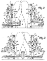
- Figure 1 is a side view of a milking box;
- Figure 2 is a rear view of a milking robot, a teat cup being connected to a teat of an animal standing in the milking box;
- Figure 3 is a rear view of the milking robot, wherein the teat cups are connected to the teats of an animal present in the milking box and wherein the robot arm is thereafter retracted to outside the milking box;
- Figure 4 is a plan view of the milking box with the milking robot, wherein the teat cups have all four been connected to the teats of an animal standing in the milking box and wherein the robot arms have thereafter been retracted to outside the milking box;
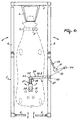
- Figure 5 is a side view of a milking box accommodating a cow, of which the front and rear teats are at unequal heights, and in which figure a detector is shown in the position in which it can determine the location of the rear teats, and
- Figure 6 is a plan view of the milking box shown in Figure 5 containing the detector, and the manner in which this detector is movable and cleanable.
-
- Figure 1 shows, in a side view, a
milking box 1 in which a cow to be milked is present. Themilking box 1 includes arailing 2 which limits the milking box at all four sides, anentrance door 3 at the rear side and twoexit doors 4 and 5 having been arranged in this railing at the two longitudinal sides (see Figure 4). Via one of these exit doors the animal can be conducted from the milking box to a shed area or a pasture, whilst via the other door the animal can be conducted to a special isolation area, e.g. because mastitis has been detected during milking. The entrance and exit doors are under the control of a computer system, not further shown. At the leading side of the milking box 1 afeeding trough 6 has been disposed, which is part of an automatic feeding system. The animals to be milked wear acollar 7, which is equipped with a transponder 8 which cooperates with a sensor 9 disposed at or near thefeeding trough 6. When an animal enters themilking box 1 and has advanced that far that it can put its head into thefeeding trough 6, the distance between the transponder 8 and the sensor 9 is such that communication between the two elements 8 and 9 occurs. The transponder 8 and the sensor 9, which is connected to the computer system, constitute an animal identification system. As soon as communication between the transponder 8 and the sensor 9 becomes possible, the animal is identified, which has for its result that a file stored for this animal in the memory of the computer system becomes accessible, which file includes various data, such as data for the automatic supply of food, the automatic connection of the teat cups and the subsequent automatic milking operation and for monitoring the heath condition of this animal. - After the animal has entered the
milking box 1 and has been identified therein, adetector 10, here in the form of a laser detector, is moved to under the animal. In the Figures 1 and 4, thedetector 10 is disposed on arobot arm system 11, formed byrobot arms vertical shafts robot arm system 11 being attached to therailing 2 in such a manner that it is pivotal about theshaft 13. Therobot arms motors detector 10, the position of the teats relative to themilking box 1 can be determined, whereafterteat cups 18 can be fitted on the teats. Thedetector 10 and the means for fitting theteat cups 18 to the teats together form a milking robot. In the embodiment shown, these means include a separate robot arm construction 9 for each of theteat cups 18. Such arobot arm construction 19 includes a first four-bar linkage 20, with the aid of which avertical carrier 21 is connected capable of moving in the upward direction to frameportions 22 of therailing 2. The pivotal shafts, by means of which this four-bar linkage is connected to the frame portions, are denoted by 20A. At the lower side of thecarrier 21 there is present a second four-bar linkage 23, with the aid of which arobot arm 24 is movable from outside themilking box 1 into the milking box to under an animal present therein and can again be retracted to outside the milking box. Thisrobot arm 24 is furthermore pivotal about avertical shaft 25 relative to thecarrier 21. Each of therobot arms 24 acts as a carrier for one or theteat cups 18. By means of the first and second four-bar linkages shaft 25, theteat cup 18 connected to therobot arm 24 can be moved omnidirectionally. In the embodiment shown, the pivotal motion of therobot arm 24 round theshaft 25 is realized by a computer-controlledmotor 14, the reciprocal motion of therobot arm 24 relative to thecarrier 21 by a computer-controlledmotor 17, whilst the up-and-down motion is realized with the aid of the first four-bar linkage by a computer-controlledoperating cylinder 41, preferably a pneumatic cylinder. Themotors - A
teat cup 18 is connected to therobot arm 24 by means of a flexible element, such as acord 26, which cord is not only connected to ateat cup 18 but also to an operating cylinder, preferably a pneumatic cylinder, accommodated in therobot arm 24. If, as is shown in Figure 2, ateat cup 18, carried by therobot arm 24, is fitted on a teat, then, as soon as theteat cup 18 has been sucked to the teat with the aid of the vacuum produced therein, the cylinder accommodated in therobot arm 24 will be enabled, so that therobot arm 24 can be retracted to outside themilking box 1 and theteat cup 18 remains connected to therobot arm 24 only by thecord 26 and will, therefore, have a sufficient freedom of movement to track the animal's movements. In this situation, it may happen that theteat cups 18 are inhibited in their free motional capability bymilk tubes 27 andpossible pulsation tubes 28, more in particular when these tubes have been secured to therobot arm construction 19. It is, therefore, advantageous when thetubes teat cups 18 when they follow the animal's movements. To that end, thetubes teat cups 18 extend during milking, taken in a plan view, from the teat cups to which these tubes are connected, obliquely forwardly in the direction of walk of the animal and outwardly and thereafter the tubes extend in the shape of a loop (see Figure 4). From the teat cups thetubes connection 29, provided at the side of the milking box, for thetubes robot arm constructions 19 are disposed on both sides of themilking box 1, only one point ofconnection 29 on both sides is sufficient. Of course, there may be a point of connection for thetubes robot arms 24 are movable from outside the box obliquely rearwardly and inwardly to under the animal, thetubes relevant robot arm 24 is located, whereafter the tubes extend in the shape of a loop transversely underneath the robot arm to the relevant point ofconnection 29. As between theteat cups 18 and the points ofconnection 29 the tubes are not connected to anything else, they can move freely near the milking box floor. Consequently, they experience a slight resistance and will substantially not obstruct the motion of the teat cups. When the teat cups have been connected to the teats, then thetubes robot arms 24 can be energized in order to pull the teat cups up against the holder at the end of therobot arm 24. Since there are fourrobot arm constructions 19 which operate independently of each other, the teat cups can be coupled both simultaneously and one after the other and independently of each other to the teats of an animal. Also uncoupling of a teat cup can be effected independently of the other teat cups. - When, after the milking operation has ended, a
teat cup 18 has been pulled up against arelevant robot arm 24 and this arm has thereafter been returned to its position of rest outside the milking box, the teat cup can be automatically cleaned in this rest position. To that end (see Figures 1 to 3), spray heads 42 connected to a (non-shown) washing circuit are positioned at or near both sides of the milking box. Teat cups are connectable independently of each other to these spray heads 42, more in particular when therobot arms 24 carrying the teat cups 18 have been moved to their position of rest. - Contrary to the cow standing in the milking box shown in Figure 1, the cow in the milking box shown in Figure 5 has teats which are at unequal heights. It regularly happens that cows have teats which are located very closely next to each other and/or are at different heights. Because of the advantageous construction of a separate robot arm structure for the
detector 10, it becomes possible to determine also the position of such teats. Such a robot arm structure for thedetector 10 is illustrated in Figures 5 and 6. The means for the connection of the teat cups have been omitted from these drawings. Thedetector 10 is located on arobot arm structure 30, which is of such a design that the detector is omnidirectionally or substantially omnidirectionally movable in the milking box. Thedetector 10 is connected via a four-bar linkage 31 to arobot arm 32, which is part of therobot arm structure 30. Therobot arm 32 is pivotal about avertical shaft 33, arranged at the side of themilking box 1. The four-bar linkage 31 itself is connected capable of pivoting about avertical shaft 34 to therobot arm 32. Thedetector 10 is further connected, capable of pivoting about its own longitudinal shaft 35, to the four-bar linkage 31 (see Figure 5). Because of the feature that it is pivotal about theshafts bar linkage 31, thedetector 10 can move around the teats in all positions and more particularly always in such a position that the teats can be detected, whatever their positions relative to each other. The four-bar linkage 31 and the pivotability of thedetector 10 about its own longitudinal shaft 35 renders it possible for the detector to effect a scanning motion in different directions, so that also teats differing from normal teats can be detected. The scanning motion in the upward direction can then be effected through at least approximately five centimetres and can preferably amount to approximately ten centimetres in the vertical direction. Should there be animals of which the difference in height between the front and rear teats of the udder is still larger, then the pivotal motion can be adapted thereto. - In an embodiment of the invention, the detector is constituted by a laser detector and positioned as such in a housing having a window, through which the laser beam is transmitted. When this window gets dirty, the detection of the teats may not be sufficiently accurate. It is, therefore, important to provide the implement with means, with which the
detector 10 can be cleaned. To enable cleaning in an efficient manner, the pivotal motion about theshafts detector 10 can be moved to outside themilking box 1 to a cleaning position, as indicated by broken lines in Figure 6. In this position, the detector can then be cleaned using a cleaningmember 36 provided for that purpose. This cleaningmember 36 may include spraying and/or blowing means for spraying a cleaning agent or blowing air against the window of thedetector 10, respectively. - Performing the pivotal motions about the
shafts bar linkage 31, as well as the rotation of thedetector 10 about its own longitudinal shaft are monitored by computer-controlled motors, preferably steppingmotors detector 10 to be operative in a plurality of positions to enable a determination of the position of the various teats. Thus, it may be necessary for thedetector 10 to be arranged for the determination of the position of the front teats in a first working position in the midway point between and before the leading teats, whilst for the determination of the position of the trailing teats the detector must be placed in a position further to the rear. It may alternatively be possible that the detector must not be arranged in the midway point between the teats, but more to the side; the latter will more specifically be the case when one teat would be in the shadow of the other teat relative to the detector or when two teats are very close to each other. Since the relative position of the teats of the several animals is known, this can be taken into account on arranging the detector in the working position under the animal. The computer system may include a control programme adapted to the individual animals for moving the detector to an animal-specific position under the udder, which control programme can be addressed with the aid of the animal identification system for the relevant animal. This animal-attuned control program can be triggered on the basis of data present in the computer system in the data file for each animal. Thedetector 10 consequently has a position of rest (indicated by broken lines in Figure 4), as well as a cleaning position (see Figure 6) and one or more working positions adapted to the individual animals. - The invention is in no way limited to the embodiments described here, but also comprises all the modifications which may be applied by a person skilled in the art and which are within the scope of the claims described hereafter.
Claims (6)
- A construction including an implement for automatically milking animals, such as cows, having one or more milking boxes (1) and one or more milking robots for automatically connecting teat cups to the teats of the animals, whilst the implement includes a detector (10) for determining the position of the teats, said implement further including a cleaning member (36) for cleaning the detector (10), characterized in that the cleaning member (36) includes spraying and/or blowing means for spraying a cleaning liquid and/or blowing air against the window of the detector (10).
- A construction as claimed in claim 1, characterized in that the cleaning member (36) is disposed, in connection with the side wall (5) of the milking box (1), outside the milking box (1).
- A construction as claimed in claim 1 or 2, characterized in that the detector (10) is constituted by a laser.
- A construction as claimed in any one of the preceding claims, characterized in that moving the component parts of the robot arm construction and moving the detector (10) is performed by means of computer-controlled stepping motors.
- A construction as claimed in any one of the preceding claims, characterized in that the implement includes an animal identification system connected to a computer, in which computer a control programme adapted to the individual animals for moving the detector (10) to an animal-specific position under the udder is stored.
- A construction as claimed in any one of the preceding claims, characterized in that the implement is arranged such that optionally the four teat cups (18) are couplable simultaneously or one after the other to the teats of an animal, whilst the teat cups (18) are further individually uncouplable.
Priority Applications (1)
| Application Number | Priority Date | Filing Date | Title |
|---|---|---|---|
| EP04077371A EP1481583B1 (en) | 1994-07-04 | 1995-06-29 | A construction including an implement for automatically milking animals |
Applications Claiming Priority (3)
| Application Number | Priority Date | Filing Date | Title |
|---|---|---|---|
| NL9401113A NL9401113A (en) | 1994-07-04 | 1994-07-04 | Construction with a device for automatic milking of animals. |
| NL9401113 | 1994-07-04 | ||
| EP95923587A EP0716566B1 (en) | 1994-07-04 | 1995-06-29 | A construction including an implement for automatically milking animals |
Related Parent Applications (1)
| Application Number | Title | Priority Date | Filing Date |
|---|---|---|---|
| EP95923587A Division EP0716566B1 (en) | 1994-07-04 | 1995-06-29 | A construction including an implement for automatically milking animals |
Related Child Applications (1)
| Application Number | Title | Priority Date | Filing Date |
|---|---|---|---|
| EP04077371A Division EP1481583B1 (en) | 1994-07-04 | 1995-06-29 | A construction including an implement for automatically milking animals |
Publications (3)
| Publication Number | Publication Date |
|---|---|
| EP1120033A2 EP1120033A2 (en) | 2001-08-01 |
| EP1120033A3 EP1120033A3 (en) | 2002-05-22 |
| EP1120033B1 true EP1120033B1 (en) | 2005-11-02 |
Family
ID=19864404
Family Applications (4)
| Application Number | Title | Priority Date | Filing Date |
|---|---|---|---|
| EP04077371A Revoked EP1481583B1 (en) | 1994-07-04 | 1995-06-29 | A construction including an implement for automatically milking animals |
| EP95923587A Expired - Lifetime EP0716566B1 (en) | 1994-07-04 | 1995-06-29 | A construction including an implement for automatically milking animals |
| EP01201695A Revoked EP1120033B1 (en) | 1994-07-04 | 1995-06-29 | Construction including an implement for automatically milking animals |
| EP01201697A Expired - Lifetime EP1120034B1 (en) | 1994-07-04 | 1995-06-29 | A construction including an implement for automatically milking animals |
Family Applications Before (2)
| Application Number | Title | Priority Date | Filing Date |
|---|---|---|---|
| EP04077371A Revoked EP1481583B1 (en) | 1994-07-04 | 1995-06-29 | A construction including an implement for automatically milking animals |
| EP95923587A Expired - Lifetime EP0716566B1 (en) | 1994-07-04 | 1995-06-29 | A construction including an implement for automatically milking animals |
Family Applications After (1)
| Application Number | Title | Priority Date | Filing Date |
|---|---|---|---|
| EP01201697A Expired - Lifetime EP1120034B1 (en) | 1994-07-04 | 1995-06-29 | A construction including an implement for automatically milking animals |
Country Status (8)
| Country | Link |
|---|---|
| US (2) | US5784994A (en) |
| EP (4) | EP1481583B1 (en) |
| JP (1) | JPH09502362A (en) |
| CA (1) | CA2170046A1 (en) |
| DE (4) | DE69524042T2 (en) |
| NL (1) | NL9401113A (en) |
| NZ (1) | NZ288747A (en) |
| WO (1) | WO1996001040A2 (en) |
Families Citing this family (92)
| Publication number | Priority date | Publication date | Assignee | Title |
|---|---|---|---|---|
| GB9113405D0 (en) * | 1991-06-20 | 1991-08-07 | Silsoe Research Inst | Automatic milking |
| SE9503792D0 (en) * | 1995-10-27 | 1995-10-27 | Tetra Laval Holdings & Finance | Teat location for milking |
| SE9503793D0 (en) * | 1995-10-27 | 1995-10-27 | Tetra Laval Holdings & Finance | An apparatus for moving an animal related means and a method therefor |
| US6116188A (en) * | 1996-04-24 | 2000-09-12 | Van Der Lely; Cornelis | Method of milking animals |
| SE9602878D0 (en) * | 1996-07-26 | 1996-07-26 | Tetra Laval Holdings & Finance | A stall for housing an animal to be subjected to an animal-related action |
| NL1004406C2 (en) * | 1996-08-01 | 1998-02-05 | Maasland Nv | Device for automatic milking of animals. |
| SE9603054D0 (en) * | 1996-08-22 | 1996-08-22 | Tetra Laval Holdings & Finance | An arrangement for and a method of performing an animal-related action |
| US6148766A (en) * | 1996-12-17 | 2000-11-21 | Van Der Lely; Cornelis | Construction including an implement for automatically milking animals |
| SE9701231D0 (en) * | 1997-04-04 | 1997-04-04 | Alfa Laval Agri Ab | Apparatus and method for recognizing and determining the position of part of an animal |
| SE9701310D0 (en) * | 1997-04-11 | 1997-04-11 | Alfa Laval Agri Ab | A teatcup magazine, a milking arrangement, and a method of handling a teatcup |
| SE9701547D0 (en) * | 1997-04-23 | 1997-04-23 | Alfa Laval Agri Ab | Apparatus and method for recognizing and determining the positon of a part of an animal |
| NL1006175C2 (en) * | 1997-05-30 | 1998-12-01 | Maasland Nv | Device for milking animals. |
| SE9702543D0 (en) * | 1997-07-01 | 1997-07-01 | Alfa Laval Agri Ab | A milking stall |
| AU1267499A (en) * | 1997-11-14 | 1999-06-07 | Delaval Holding Ab | An apparatus for performing an animal related operation |
| SE517285C2 (en) * | 1998-07-24 | 2002-05-21 | Delaval Holding Ab | Apparatus for automatic milking of an animal |
| SE522443C2 (en) | 1999-04-19 | 2004-02-10 | Delaval Holding Ab | Method and apparatus for recognizing and determining a position and a robot including such a device |
| NL1016023C2 (en) * | 2000-08-25 | 2002-02-26 | Idento Electronics Bv | Milking device and holder for receiving teat cups. |
| NL1016237C2 (en) * | 2000-09-22 | 2002-03-25 | Rieberjo B V | Milking implement provided with cleaning agents. |
| NL1017338C2 (en) * | 2001-02-12 | 2002-08-13 | Lely Entpr Ag | Cleaning device. |
| SE519056C3 (en) * | 2001-05-10 | 2003-02-19 | Delaval Holding Ab | Device for carrying a milking device |
| SE519055C2 (en) * | 2001-05-10 | 2003-01-07 | Delaval Holding Ab | Apparatus for carrying a milking device and method for carrying a milking device |
| US7055458B2 (en) * | 2002-01-31 | 2006-06-06 | Fangjiang Guo | System for the presentation of animals to be milked and method |
| NL1020004C2 (en) * | 2002-02-19 | 2003-08-21 | Lely Entpr Ag | Assembly for feeding and milking animals, and method for feeding and for milking animals. |
| NL1020783C2 (en) * | 2002-06-06 | 2003-12-09 | Lely Entpr Ag | Method and device for automatically milking an animal. |
| NL1020784C2 (en) * | 2002-06-06 | 2003-12-09 | Lely Entpr Ag | Device for automatically milking an animal. |
| US7086348B2 (en) * | 2002-07-17 | 2006-08-08 | Fangjiang Guo | Milking parlor for the forward straight line animal ambulation and individual presentation of an animal to be milked in a milking stall located intermediate a holding area and a release area |
| US6814026B2 (en) * | 2002-08-02 | 2004-11-09 | Fangjiang Guo | Milking parlor and method for individually presenting animals to be milked via a translating shuttle stall |
| US6814027B2 (en) * | 2002-09-12 | 2004-11-09 | Westfaliasurge, Inc. | Milker unit detacher for rotary milking parlor |
| NZ523369A (en) | 2002-12-20 | 2005-08-26 | Dec Int Nz Ltd | Milk processing |
| NL1022565C2 (en) * | 2003-02-03 | 2004-08-04 | Lely Entpr Ag | Device for automatically milking an animal. |
| WO2004100652A2 (en) * | 2003-05-12 | 2004-11-25 | Bryan Fung | Chew-resistant pet bed |
| EP1520468B1 (en) | 2003-09-30 | 2006-04-26 | Lely Enterprises AG | A device for and a method of milking a dairy animal |
| US8117989B2 (en) | 2008-06-27 | 2012-02-21 | Gea Farm Technologies, Inc. | Milk tube dome with flow controller |
| US10874084B2 (en) | 2004-06-12 | 2020-12-29 | Gea Farm Technologies, Inc. | Safety valve for a dairy system component |
| US8033247B2 (en) | 2004-06-12 | 2011-10-11 | Gea Farm Technologies, Inc. | Automatic dairy animal milker unit backflusher and teat dip applicator system and method |
| US8342125B2 (en) | 2004-06-12 | 2013-01-01 | Gea Farm Technologies, Inc. | Safety valve for an automatic dairy animal milker unit backflusher and teat dip applicator |
| US8025029B2 (en) * | 2004-06-12 | 2011-09-27 | Gea Farm Technologies, Inc. | Automatic dairy animal milker unit backflusher and teat dip applicator system and method |
| SE529127C2 (en) * | 2005-09-02 | 2007-05-08 | Delaval Holding Ab | Detection arrangement and method of magnetic gripping device |
| EP1913811B1 (en) * | 2006-10-18 | 2014-02-26 | DeLaval Holding AB | Cleaning within a milking system |
| US20090007847A1 (en) * | 2007-07-07 | 2009-01-08 | Arkadi Relin | Method of dynamic milking |
| EP2355652B2 (en) * | 2008-11-10 | 2021-03-17 | GEA Farm Technologies GmbH | Method and device for automatically bringing a fluid into contact with the teats of an animal |
| NL1036477C2 (en) | 2009-01-28 | 2010-07-30 | Lely Patent Nv | DEVICE FOR PERFORMING WORK IN A SPACE, IN PARTICULAR A STABLE. |
| US11723341B2 (en) | 2009-09-04 | 2023-08-15 | Gea Farm Technologies, Inc. | Safety valve for an automated milker unit backflushing and teat dip applicator system |
| US8770146B2 (en) | 2009-09-04 | 2014-07-08 | Gea Farm Technologies, Inc. | Methods and apparatus for applying teat dip to a dairy animal |
| RU2676917C2 (en) | 2010-02-22 | 2019-01-11 | Геа Фарм Технолоджис, Инк. | Apparatus for milking and milk collection with milk line protection |
| US20120097107A1 (en) | 2010-02-22 | 2012-04-26 | Gea Farm Technologies, Inc. | Dairy animal milking preparation system and methods |
| RU2566704C2 (en) * | 2010-06-03 | 2015-10-27 | Делаваль Холдинг Аб | Milking robot and milking system |
| CA2801648A1 (en) * | 2010-06-04 | 2011-12-08 | Promat Inc. | Modular manipulation device |
| US9161511B2 (en) | 2010-07-06 | 2015-10-20 | Technologies Holdings Corp. | Automated rotary milking system |
| US10111401B2 (en) | 2010-08-31 | 2018-10-30 | Technologies Holdings Corp. | System and method for determining whether to operate a robot in conjunction with a rotary parlor |
| US9149018B2 (en) | 2010-08-31 | 2015-10-06 | Technologies Holdings Corp. | System and method for determining whether to operate a robot in conjunction with a rotary milking platform based on detection of a milking claw |
| US8800487B2 (en) | 2010-08-31 | 2014-08-12 | Technologies Holdings Corp. | System and method for controlling the position of a robot carriage based on the position of a milking stall of an adjacent rotary milking platform |
| US8707905B2 (en) | 2010-08-31 | 2014-04-29 | Technologies Holdings Corp. | Automated system for applying disinfectant to the teats of dairy livestock |
| US20130180455A1 (en) * | 2010-10-26 | 2013-07-18 | Delaval Holding Ab | Control system for at least one flexible tubular element connected to a cup-shaped member |
| US8776722B2 (en) | 2010-12-22 | 2014-07-15 | Delaval Holding Ab | Method and apparatus for protecting an optical detection device from contamination |
| EP2685810B1 (en) | 2011-03-17 | 2020-09-09 | Mirobot Ltd. | Human assisted milking robot and method |
| WO2012123948A1 (en) | 2011-03-17 | 2012-09-20 | Mirobot Ltd. | System and method for three dimensional teat modeling for use with a milking system |
| DE102011001404A1 (en) | 2011-03-18 | 2012-09-20 | Gea Farm Technologies Gmbh | Milking parlor and milking parlor with such a milking parlor |
| EP3335548B1 (en) | 2011-03-18 | 2021-03-10 | GEA Farm Technologies GmbH | Teat cup and a milking stall including such a teat cup |
| US9265227B2 (en) | 2011-04-28 | 2016-02-23 | Technologies Holdings Corp. | System and method for improved attachment of a cup to a dairy animal |
| US9107379B2 (en) | 2011-04-28 | 2015-08-18 | Technologies Holdings Corp. | Arrangement of milking box stalls |
| US9215861B2 (en) * | 2011-04-28 | 2015-12-22 | Technologies Holdings Corp. | Milking box with robotic attacher and backplane for tracking movements of a dairy animal |
| US10357015B2 (en) | 2011-04-28 | 2019-07-23 | Technologies Holdings Corp. | Robotic arm with double grabber and method of operation |
| US9043988B2 (en) | 2011-04-28 | 2015-06-02 | Technologies Holdings Corp. | Milking box with storage area for teat cups |
| US9049843B2 (en) | 2011-04-28 | 2015-06-09 | Technologies Holdings Corp. | Milking box with a robotic attacher having a three-dimensional range of motion |
| US9357744B2 (en) | 2011-04-28 | 2016-06-07 | Technologies Holdings Corp. | Cleaning system for a milking box stall |
| US9161512B2 (en) | 2011-04-28 | 2015-10-20 | Technologies Holdings Corp. | Milking box with robotic attacher comprising an arm that pivots, rotates, and grips |
| US9258975B2 (en) | 2011-04-28 | 2016-02-16 | Technologies Holdings Corp. | Milking box with robotic attacher and vision system |
| US8683946B2 (en) | 2011-04-28 | 2014-04-01 | Technologies Holdings Corp. | System and method of attaching cups to a dairy animal |
| US9058657B2 (en) | 2011-04-28 | 2015-06-16 | Technologies Holdings Corp. | System and method for filtering data captured by a 3D camera |
| US8671885B2 (en) | 2011-04-28 | 2014-03-18 | Technologies Holdings Corp. | Vision system for robotic attacher |
| US10127446B2 (en) | 2011-04-28 | 2018-11-13 | Technologies Holdings Corp. | System and method for filtering data captured by a 2D camera |
| US8885891B2 (en) * | 2011-04-28 | 2014-11-11 | Technologies Holdings Corp. | System and method for analyzing data captured by a three-dimensional camera |
| US8903129B2 (en) | 2011-04-28 | 2014-12-02 | Technologies Holdings Corp. | System and method for filtering data captured by a 2D camera |
| US8746176B2 (en) | 2011-04-28 | 2014-06-10 | Technologies Holdings Corp. | System and method of attaching a cup to a dairy animal according to a sequence |
| US9107378B2 (en) | 2011-04-28 | 2015-08-18 | Technologies Holdings Corp. | Milking box with robotic attacher |
| US9681634B2 (en) | 2011-04-28 | 2017-06-20 | Technologies Holdings Corp. | System and method to determine a teat position using edge detection in rear images of a livestock from two cameras |
| AU2012346585B2 (en) * | 2011-12-02 | 2017-01-12 | Delaval Holding Ab | Camera cleaning system and method and rotary milking system |
| US9675043B2 (en) * | 2011-12-16 | 2017-06-13 | Delaval Holding Ab | Rotary parlour arranged to house animals to be milked |
| DE102012110501A1 (en) | 2012-03-14 | 2013-09-19 | Gea Farm Technologies Gmbh | Divider of a milking parlor arrangement and milking parlor arrangement |
| DE102012102133A1 (en) | 2012-03-14 | 2013-09-19 | Gea Farm Technologies Gmbh | MELSTAND ASSEMBLY WITH AN INNER ROBOT DEVICE |
| US9545078B1 (en) * | 2012-06-07 | 2017-01-17 | Lely Patent N.V. | Electro-hydraulical actuator for a robot arm |
| NL2011202C2 (en) * | 2013-07-19 | 2015-01-21 | Rotec Engineering B V | CLEANING DEVICE FOR CLEANING TEATS OF AN MILK TO BE LIQUIDED, MILK MACHINE PROVIDED THEREOF AND METHOD THEREFORE. |
| GB201318641D0 (en) | 2013-10-22 | 2013-12-04 | Fullwood & Bland Ltd | Automatic milking stall |
| US9526224B2 (en) | 2013-12-20 | 2016-12-27 | Gea Farm Technologies Gmbh | Safety valve device |
| DE102013114595A1 (en) | 2013-12-20 | 2015-06-25 | Gea Farm Technologies Gmbh | safety valve |
| DE102014107124A1 (en) | 2014-05-20 | 2015-11-26 | Gea Farm Technologies Gmbh | Arm arrangement for a milking parlor arrangement for the automatic milking of dairy animals, divider of a milking parlor arrangement and milking parlor arrangement |
| NL2014014B1 (en) | 2014-12-19 | 2016-10-12 | Triodor Arge | Autonomously movable, unmanned vehicle for cleaning a surface in a barn. |
| DE102016108300A1 (en) | 2016-05-04 | 2017-11-09 | Gea Farm Technologies Gmbh | safety valve |
| US10407854B2 (en) * | 2017-05-12 | 2019-09-10 | Groupe Crh Canada Inc. | Joint sawing system for concrete barriers |
| US11617343B2 (en) | 2017-11-03 | 2023-04-04 | Gea Farm Technologies Gmbh | Automated teat dip fluid manifold |
| US11051484B2 (en) | 2019-10-02 | 2021-07-06 | Farm Improvements Limited | Sprayer with articulated arm and sensor system |
Family Cites Families (14)
| Publication number | Priority date | Publication date | Assignee | Title |
|---|---|---|---|---|
| US2226946A (en) * | 1936-03-14 | 1940-12-31 | John F Russell | Method of and apparatus for handling milk |
| NL8600076A (en) * | 1986-01-16 | 1987-08-17 | Lely Nv C Van Der | METHOD AND APPARATUS FOR MILKING AN ANIMAL. |
| DE3775773D1 (en) * | 1987-09-08 | 1992-02-13 | Cemagref | AUTOMATIC MILKING MACHINE. |
| EP0323875A3 (en) * | 1988-01-08 | 1989-11-15 | Prolion B.V. | Ultrasonic detector, methods for searching a moving object, ultrasonic sensor unit, element for positioning an animal, terminal apparatus for an automatic milking system, and method for automatically milking an animal |
| NL8802332A (en) * | 1988-09-21 | 1990-04-17 | Lely Nv C Van Der | APPARATUS FOR MILKING AN ANIMAL. |
| DE3938077C2 (en) * | 1989-11-16 | 2000-12-07 | Westfalia Landtechnik Gmbh | Method and device for locating teats to be milked automatically |
| NL9001076A (en) * | 1990-05-04 | 1991-12-02 | Lely Nv C Van Der | DEVICE FOR DETERMINING THE DISTANCE OF AN APPARATUS TO AN OBJECT. |
| US5245947A (en) * | 1991-05-17 | 1993-09-21 | Prolion B.V. | Milking cup and a milking set provided with one or more such milking cups and an automatic milking apparatus |
| NL9200051A (en) * | 1992-01-13 | 1993-08-02 | Prolion Bv | AUTOMATIC MILK EQUIPMENT. |
| NL9100992A (en) * | 1991-06-10 | 1993-01-04 | Lely Nv C Van Der | DEVICE FOR MILKING ANIMALS. |
| CA2093131A1 (en) * | 1991-06-28 | 1992-12-29 | David Parker | Manipulation of intestinal structure and enzymes in animals |
| NL9200258A (en) * | 1991-10-04 | 1993-05-03 | Lely Nv C Van Der | METHOD FOR CLEANING MILK BEAKERS AND / OR AFTER-TREATMENT OF THE WEANING OF A MILKED ANIMAL, ANIMAL MILKING APPARATUS FOR USING THIS METHOD (S), AND A RINSE TOOL APPLIED IN SUCH AN APPARATUS. |
| NL9200091A (en) * | 1992-01-17 | 1993-08-16 | Lely Nv C Van Der | MILK MACHINE. |
| NL9200639A (en) * | 1992-04-06 | 1993-11-01 | Lely Nv C Van Der | DEVICE FOR AUTOMATIC MILKING OF ANIMALS. |
-
1994
- 1994-07-04 NL NL9401113A patent/NL9401113A/en not_active Application Discontinuation
-
1995
- 1995-06-29 DE DE69524042T patent/DE69524042T2/en not_active Expired - Lifetime
- 1995-06-29 EP EP04077371A patent/EP1481583B1/en not_active Revoked
- 1995-06-29 EP EP95923587A patent/EP0716566B1/en not_active Expired - Lifetime
- 1995-06-29 JP JP8503555A patent/JPH09502362A/en not_active Ceased
- 1995-06-29 DE DE69533971T patent/DE69533971T2/en not_active Expired - Fee Related
- 1995-06-29 WO PCT/NL1995/000230 patent/WO1996001040A2/en active IP Right Grant
- 1995-06-29 EP EP01201695A patent/EP1120033B1/en not_active Revoked
- 1995-06-29 EP EP01201697A patent/EP1120034B1/en not_active Expired - Lifetime
- 1995-06-29 NZ NZ288747A patent/NZ288747A/en unknown
- 1995-06-29 DE DE69534572T patent/DE69534572T2/en not_active Revoked
- 1995-06-29 US US08/596,360 patent/US5784994A/en not_active Expired - Lifetime
- 1995-06-29 DE DE69534866T patent/DE69534866T2/en not_active Revoked
- 1995-06-29 CA CA002170046A patent/CA2170046A1/en not_active Abandoned
-
1998
- 1998-07-24 US US09/121,901 patent/US6009833A/en not_active Expired - Lifetime
Also Published As
| Publication number | Publication date |
|---|---|
| DE69524042D1 (en) | 2002-01-03 |
| WO1996001040A2 (en) | 1996-01-18 |
| NZ288747A (en) | 1997-02-24 |
| EP0716566A1 (en) | 1996-06-19 |
| EP1120034B1 (en) | 2005-01-26 |
| US6009833A (en) | 2000-01-04 |
| EP1120033A2 (en) | 2001-08-01 |
| DE69534572T2 (en) | 2006-07-27 |
| DE69534866D1 (en) | 2006-05-11 |
| DE69524042T2 (en) | 2002-07-11 |
| EP1481583A3 (en) | 2005-01-12 |
| JPH09502362A (en) | 1997-03-11 |
| EP1120033A3 (en) | 2002-05-22 |
| DE69533971T2 (en) | 2006-03-30 |
| EP1481583A2 (en) | 2004-12-01 |
| DE69534866T2 (en) | 2006-09-21 |
| EP1481583B1 (en) | 2006-03-15 |
| NL9401113A (en) | 1996-02-01 |
| EP1120034A2 (en) | 2001-08-01 |
| CA2170046A1 (en) | 1996-01-18 |
| EP1120034A3 (en) | 2002-03-27 |
| US5784994A (en) | 1998-07-28 |
| DE69534572D1 (en) | 2005-12-08 |
| EP0716566B1 (en) | 2001-11-21 |
| WO1996001040A3 (en) | 1996-02-22 |
| DE69533971D1 (en) | 2005-03-03 |
Similar Documents
| Publication | Publication Date | Title |
|---|---|---|
| EP1120033B1 (en) | Construction including an implement for automatically milking animals | |
| EP0188303B1 (en) | Implement for automatically milking an animal | |
| EP0591288B1 (en) | Automatic milking | |
| EP0319523B1 (en) | Device for automatically milking an animal | |
| US4867103A (en) | Automatic milking installation | |
| EP2701492B1 (en) | Milking box with robotic attacher | |
| EP0565189B1 (en) | A construction for automatically milking animals | |
| EP1021947B1 (en) | A method of milking animals, such as cows | |
| EP1258189B1 (en) | A construction including an implement for automatically milking animals | |
| EP0777961A1 (en) | An implement for milking animals | |
| EP0880889A3 (en) | An implement for milking animals | |
| JPH09243315A (en) | Device for measuring position of bodily part of walking animal and milking device | |
| EP0323444B1 (en) | A device for milking animals, such as cows | |
| EP0638231B1 (en) | A construction for automatically milking animals | |
| WO1999031970A1 (en) | An animal related apparatus | |
| EP0638232B2 (en) | A construction for automatically milking animals | |
| EP0634095B1 (en) | A construction for automatically milking animals | |
| RU2071247C1 (en) | Milking unit | |
| EP1252817A2 (en) | A construction including an implement for automatically milking animals |
Legal Events
| Date | Code | Title | Description |
|---|---|---|---|
| PUAI | Public reference made under article 153(3) epc to a published international application that has entered the european phase |
Free format text: ORIGINAL CODE: 0009012 |
|
| AC | Divisional application: reference to earlier application |
Ref document number: 716566 Country of ref document: EP |
|
| AK | Designated contracting states |
Kind code of ref document: A2 Designated state(s): DE FR GB NL SE |
|
| RIC1 | Information provided on ipc code assigned before grant |
Free format text: 7A 01J 5/017 A, 7A 01K 1/12 B |
|
| PUAL | Search report despatched |
Free format text: ORIGINAL CODE: 0009013 |
|
| 17P | Request for examination filed |
Effective date: 20020924 |
|
| AKX | Designation fees paid |
Designated state(s): DE FR GB NL SE |
|
| RAP1 | Party data changed (applicant data changed or rights of an application transferred) |
Owner name: MAASLAND N.V. |
|
| REG | Reference to a national code |
Ref country code: SE Ref legal event code: TRCL |
|
| EL | Fr: translation of claims filed | ||
| TCNL | Nl: translation of patent claims filed | ||
| GRAP | Despatch of communication of intention to grant a patent |
Free format text: ORIGINAL CODE: EPIDOSNIGR1 |
|
| RTI1 | Title (correction) |
Free format text: CONSTRUCTION INCLUDING AN IMPLEMENT FOR AUTOMATICALLY MILKING ANIMALS |
|
| GRAS | Grant fee paid |
Free format text: ORIGINAL CODE: EPIDOSNIGR3 |
|
| GRAA | (expected) grant |
Free format text: ORIGINAL CODE: 0009210 |
|
| AC | Divisional application: reference to earlier application |
Ref document number: 0716566 Country of ref document: EP Kind code of ref document: P |
|
| AK | Designated contracting states |
Kind code of ref document: B1 Designated state(s): DE FR GB NL SE |
|
| REG | Reference to a national code |
Ref country code: GB Ref legal event code: FG4D |
|
| REF | Corresponds to: |
Ref document number: 69534572 Country of ref document: DE Date of ref document: 20051208 Kind code of ref document: P |
|
| REG | Reference to a national code |
Ref country code: SE Ref legal event code: TRGR |
|
| ET | Fr: translation filed | ||
| PLBI | Opposition filed |
Free format text: ORIGINAL CODE: 0009260 |
|
| PLAX | Notice of opposition and request to file observation + time limit sent |
Free format text: ORIGINAL CODE: EPIDOSNOBS2 |
|
| 26 | Opposition filed |
Opponent name: DELAVAL INTERNATIONAL AB Effective date: 20060802 |
|
| NLR1 | Nl: opposition has been filed with the epo |
Opponent name: DELAVAL INTERNATIONAL AB |
|
| PLBB | Reply of patent proprietor to notice(s) of opposition received |
Free format text: ORIGINAL CODE: EPIDOSNOBS3 |
|
| APAH | Appeal reference modified |
Free format text: ORIGINAL CODE: EPIDOSCREFNO |
|
| APBM | Appeal reference recorded |
Free format text: ORIGINAL CODE: EPIDOSNREFNO |
|
| APBP | Date of receipt of notice of appeal recorded |
Free format text: ORIGINAL CODE: EPIDOSNNOA2O |
|
| APBQ | Date of receipt of statement of grounds of appeal recorded |
Free format text: ORIGINAL CODE: EPIDOSNNOA3O |
|
| PGFP | Annual fee paid to national office [announced via postgrant information from national office to epo] |
Ref country code: FR Payment date: 20100630 Year of fee payment: 16 |
|
| APBU | Appeal procedure closed |
Free format text: ORIGINAL CODE: EPIDOSNNOA9O |
|
| PGFP | Annual fee paid to national office [announced via postgrant information from national office to epo] |
Ref country code: NL Payment date: 20100624 Year of fee payment: 16 |
|
| PGFP | Annual fee paid to national office [announced via postgrant information from national office to epo] |
Ref country code: DE Payment date: 20100629 Year of fee payment: 16 Ref country code: GB Payment date: 20100625 Year of fee payment: 16 Ref country code: SE Payment date: 20100629 Year of fee payment: 16 |
|
| RDAF | Communication despatched that patent is revoked |
Free format text: ORIGINAL CODE: EPIDOSNREV1 |
|
| RDAG | Patent revoked |
Free format text: ORIGINAL CODE: 0009271 |
|
| STAA | Information on the status of an ep patent application or granted ep patent |
Free format text: STATUS: PATENT REVOKED |
|
| 27W | Patent revoked |
Effective date: 20101012 |
|
| GBPR | Gb: patent revoked under art. 102 of the ep convention designating the uk as contracting state |
Effective date: 20101012 |
|
| REG | Reference to a national code |
Ref country code: SE Ref legal event code: ECNC |