EP1118816A2 - Ofen und Vorrichtung zur Verbesserung der Verbrennungseigenschaften eines solchen Ofens - Google Patents
Ofen und Vorrichtung zur Verbesserung der Verbrennungseigenschaften eines solchen Ofens Download PDFInfo
- Publication number
- EP1118816A2 EP1118816A2 EP01100799A EP01100799A EP1118816A2 EP 1118816 A2 EP1118816 A2 EP 1118816A2 EP 01100799 A EP01100799 A EP 01100799A EP 01100799 A EP01100799 A EP 01100799A EP 1118816 A2 EP1118816 A2 EP 1118816A2
- Authority
- EP
- European Patent Office
- Prior art keywords
- throttle
- control circuit
- probe
- valve member
- furnace
- Prior art date
- Legal status (The legal status is an assumption and is not a legal conclusion. Google has not performed a legal analysis and makes no representation as to the accuracy of the status listed.)
- Granted
Links
Images

Classifications
-
- F—MECHANICAL ENGINEERING; LIGHTING; HEATING; WEAPONS; BLASTING
- F24—HEATING; RANGES; VENTILATING
- F24B—DOMESTIC STOVES OR RANGES FOR SOLID FUELS; IMPLEMENTS FOR USE IN CONNECTION WITH STOVES OR RANGES
- F24B1/00—Stoves or ranges
- F24B1/02—Closed stoves
- F24B1/028—Closed stoves with means for regulating combustion
-
- F—MECHANICAL ENGINEERING; LIGHTING; HEATING; WEAPONS; BLASTING
- F23—COMBUSTION APPARATUS; COMBUSTION PROCESSES
- F23N—REGULATING OR CONTROLLING COMBUSTION
- F23N1/00—Regulating fuel supply
- F23N1/06—Regulating fuel supply conjointly with draught
- F23N1/062—Regulating fuel supply conjointly with draught using electronic means
-
- F—MECHANICAL ENGINEERING; LIGHTING; HEATING; WEAPONS; BLASTING
- F23—COMBUSTION APPARATUS; COMBUSTION PROCESSES
- F23N—REGULATING OR CONTROLLING COMBUSTION
- F23N3/00—Regulating air supply or draught
- F23N3/08—Regulating air supply or draught by power-assisted systems
- F23N3/085—Regulating air supply or draught by power-assisted systems using electrical or electromechanical means
-
- F—MECHANICAL ENGINEERING; LIGHTING; HEATING; WEAPONS; BLASTING
- F23—COMBUSTION APPARATUS; COMBUSTION PROCESSES
- F23N—REGULATING OR CONTROLLING COMBUSTION
- F23N5/00—Systems for controlling combustion
- F23N5/26—Details
-
- F—MECHANICAL ENGINEERING; LIGHTING; HEATING; WEAPONS; BLASTING
- F23—COMBUSTION APPARATUS; COMBUSTION PROCESSES
- F23N—REGULATING OR CONTROLLING COMBUSTION
- F23N2223/00—Signal processing; Details thereof
- F23N2223/08—Microprocessor; Microcomputer
-
- F—MECHANICAL ENGINEERING; LIGHTING; HEATING; WEAPONS; BLASTING
- F23—COMBUSTION APPARATUS; COMBUSTION PROCESSES
- F23N—REGULATING OR CONTROLLING COMBUSTION
- F23N2225/00—Measuring
- F23N2225/08—Measuring temperature
- F23N2225/10—Measuring temperature stack temperature
-
- F—MECHANICAL ENGINEERING; LIGHTING; HEATING; WEAPONS; BLASTING
- F23—COMBUSTION APPARATUS; COMBUSTION PROCESSES
- F23N—REGULATING OR CONTROLLING COMBUSTION
- F23N2225/00—Measuring
- F23N2225/26—Measuring humidity
- F23N2225/30—Measuring humidity measuring lambda
-
- F—MECHANICAL ENGINEERING; LIGHTING; HEATING; WEAPONS; BLASTING
- F23—COMBUSTION APPARATUS; COMBUSTION PROCESSES
- F23N—REGULATING OR CONTROLLING COMBUSTION
- F23N2235/00—Valves, nozzles or pumps
- F23N2235/02—Air or combustion gas valves or dampers
- F23N2235/04—Air or combustion gas valves or dampers in stacks
-
- F—MECHANICAL ENGINEERING; LIGHTING; HEATING; WEAPONS; BLASTING
- F23—COMBUSTION APPARATUS; COMBUSTION PROCESSES
- F23N—REGULATING OR CONTROLLING COMBUSTION
- F23N2235/00—Valves, nozzles or pumps
- F23N2235/02—Air or combustion gas valves or dampers
- F23N2235/10—Air or combustion gas valves or dampers power assisted, e.g. using electric motors
-
- F—MECHANICAL ENGINEERING; LIGHTING; HEATING; WEAPONS; BLASTING
- F23—COMBUSTION APPARATUS; COMBUSTION PROCESSES
- F23N—REGULATING OR CONTROLLING COMBUSTION
- F23N5/00—Systems for controlling combustion
- F23N5/003—Systems for controlling combustion using detectors sensitive to combustion gas properties
- F23N5/006—Systems for controlling combustion using detectors sensitive to combustion gas properties the detector being sensitive to oxygen
Definitions
- the present invention relates to an oven and an apparatus for improving the Combustion properties of such an oven.
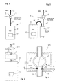
- the furnace 1 shown in FIG. 1 comprises a furnace body 2 with a door 3 closing an inner combustion chamber and a device 4 with a so-called throttle 5.
- the device 4 is connected to a chimney pipe 6, and the furnace body 2 and the device 4 are through a connecting pipe 7 for exhaust gases connected to each other.
- the furnace 11 shown in FIG. 2 comprises a furnace body 12 with a door 13 closing an internal combustion chamber and a device 14 with a throttle 15.
- the device 14 is connected to a chimney pipe 16, and the furnace body 12 and the device 14 are through connecting pipes 17 and 17 'for exhaust gases connected to a so-called heat box 18.
- the furnace 21 shown in FIG. 3 comprises a furnace body 22 with a door 23 closing an internal combustion chamber and a device 24 with a throttle 25.
- the device 24 is connected to a chimney pipe 26, and the furnace body 22 and the device 24 are through connecting pipes 27 and 27 'for exhaust gases connected to a so-called heat box 28.
- the furnace body 2, 12, 22 in Figures 1 to 3 can be of known construction and any other elements not shown in the figures.
- the heat box 18 and 28 (FIGS. 2, 3) can be, for example, a gas lintel box or a heat exchanger if necessary, for water or other purposes.
- the throttle of the facilities 4, 14 and / or 24 has a valve member, for example a tiltable flap or a sliding plate, etc.
- the device 40 according to FIG. 4 comprises a throttle 41 with a valve member, for example a flap 42, a motor or drive 43, a so-called lambda probe 44, a temperature probe 45 and a pressure probe 46.
- the drive 43 can also be arranged, for example, coaxially with the flap 42.
- the elements 44, 45 and 46 which are probes known per se, are preferably located directly below the throttle 41 and are provided in order to measure lambda values, temperature and pressure in the tube 47.
- Lambda probes are sensors that compare the oxygen content in the exhaust gas with a reference value, for example with the oxygen content in the outside air.
- the drive 43 can be a stepper motor, a linear motor, a servomotor, an actuator, a servomechanism, etc.
- the drive 43 and the probes 44, 45 and 46 are connected to a control arrangement 50 (FIG. 5) .
- the furnace according to the invention can also work with only one of the probes 44 and / or 45 and / or 46.
- the control arrangement 50 according to FIG. 5 comprises an amplifier circuit 51, a linearizer 52 and a control circuit 53, which is preferably a commercially available programmable control unit provided with a display 54, for example of the PLC type.
- the linearizer 52 can also be omitted.
- the device according to the invention comprises at least the control circuit 53 provided for the purpose of the present invention.
- the furnaces according to the invention with the device according to FIG. 4 operate as follows: One of the probes 44, 45 and / or 46, which are located in the devices 4, 14 and 24, measures a corresponding parameter. If a lambda value is preferably measured using a commercially available lambda probe, it supplies a voltage, for example in the range from -10 to 30 mV, which amplifier 51 preferably amplifies in a range from 0 to 10 volts. If necessary, a region of interest of the corresponding function can be linearized by the linearizer 52.
- the control circuit 53 constantly receives the instantaneous voltage value ⁇ (t) obtained in this way and compares it with an upper limit value Lo.
- the control circuit 53 supplies a trigger signal Sgo (FIG. 6) to the motor 43 such that it closes the flap 42 step by step or continuously, for example by an angle ⁇ um per second.
- Sgo (FIG. 6)
- the control circuit 53 supplies a trigger signal Sgu to the motor 43 such that it opens the flap step by step or continuously.
- the current lambda value will always be within the two threshold values Lo and Lu.
- the values for Lo and Lu can be determined experimentally for each furnace type.
- the signals Sgo and Sgu can be the same or similar, with another signal Sd and / or Sd 'being provided as a criterion for the direction of movement of the drive 43.
- the control circuit 53 can supply a further trigger signal Sgm if the current lambda value ⁇ (t) falls below or exceeds a medium limit value Lm such that the motor 43 then stops and the flap 42 remains in the position reached.
- the signal supplied by the temperature probe 45 is intended as a switch-on criterion for the control circuit 53 are used to control the lambda, especially at the beginning when the open is cold do not switch on immediately as long as the temperature has an upper limit To for example between 100 ° and 300 °, preferably not between 110 ° and 130 ° Has. It is also a lower temperature limit Tu, for example of the order of magnitude of 100 ° is provided to switch off the lambda control.
- the door 3 is designed such that when it is open, a door switch is activated, which the Flap 42 opens, a lamp 55 flashing and / or an acoustic signal at the same time Alarm is actuated for a predetermined time and / or a corresponding one in the display
- the display appears.
- the lambda values and the temperature and / or the pressure can be shown in the display. If the door 3 is closed again, this will result in an immediate or if necessary a delayed switch-on of the control. Will after a while De, for example after 20 minutes, the temperature limit To is not reached this is also evaluated as a special alarm, also optically and / or acoustically and / or in the display.
- the device additionally includes a changeover switch 56 manual operation or automatic operation.
Landscapes
- Engineering & Computer Science (AREA)
- Chemical & Material Sciences (AREA)
- Combustion & Propulsion (AREA)
- Mechanical Engineering (AREA)
- General Engineering & Computer Science (AREA)
- Regulation And Control Of Combustion (AREA)
- Investigating Or Analyzing Materials By The Use Of Electric Means (AREA)
- Feeding And Controlling Fuel (AREA)
- Solid-Fuel Combustion (AREA)
- Waste-Gas Treatment And Other Accessory Devices For Furnaces (AREA)
Abstract
Description
- Fig. 1 bis 3
- schematische Darstellungen verschiedener Varianten eines Ofens,
- Fig. 4
- eine schematische Darstellung einer erfindungsgemäßen Vorrichtung zur Verbesserung der Verbrennungseigenschaften eines solchen Ofens,
- Fig. 5
- ein Blockschaltbild einer Steueranordnung für einen solchen Ofen, und
- Fig. 6
- ein Impulsdiagramm zur Erläuterung der Arbeitsweise einer solchen Regelung.
Claims (10)
- Ofen für feste Brennstoffe mit einem Ofenkörper (2), der eine innere Brennkammer umfasst, und mit einer Einrichtung (40), in der eine Drossel (41) mit einem Ventilorgan (42) für Abgase untergebracht ist, dadurch gekennzeichnet, daß die Einrichtung (40) nebst einem Antrieb (43) für die Drossel mindestens eine Sonde (44) aufweist, und daß eine Vorrichtung mit einer Regelschaltung (53) zur Regelung der Drossel (41) nach Maßgabe eines von dieser Sonde (44) gelieferten Signals vorhanden ist.
- Ofen nach Anspruch 1, dadurch gekennzeichnet, daß sich die Sonde oder die Sonden unmittelbar unter dem Ventilorgan (42) der Drossel befinden.
- Ofen nach Anspruch 1 oder 2, dadurch gekennzeichnet, daß die Regelschaltung (53) ausgestaltet ist, um den momentanen durch eine Lambda-Sonde gewonnenen Lambda-Wert zwischen zwei vorgegebenen Lambda-Grenzwerten zu regeln.
- Ofen nach Anspruch 3, dadurch gekennzeichnet, daß für diese Lambda-Werte einen oberen Grenzwert Lo zwischen λ = 1,5 und λ = 2,6 und einen unteren Grenzwert zwischen λ= 1,4 und λ= 2,1 gewählt werden,
- Ofen nach einem der Ansprüche 1 bis 4, dadurch gekennzeichnet, daß die Regelschaltung (53) ausgestaltet oder programmiert ist, um bei mindestens einem durch eine Temperatur-Sonde gewonnenen Temperaturgrenzwert die Regelschaltung aus- oder einzuschalten.
- Ofen nach Anspruch 5, dadurch gekennzeichnet, daß der Temperaturgrenzwert im Bereich zwischen 100° und 300° liegt.
- Ofen nach einem der Ansprüche 1 bis 6, dadurch gekennzeichnet, daß die Regelschaltung (53) ausgestaltet oder programmiert ist, um, falls eine Tür (3; 13; 23) der Brennkammer offen ist, einen Schalter zu aktivieren, der das Ventilorgan (42) der Drossel (41) aufmacht, und um die Regelschaltung (53) zur Regelung der Drossel (41) zu reaktivieren, falls diese Tür wieder geschlossen wird.
- Ofen nach einem der Ansprüche 1 bis 7, dadurch gekennzeichnet, daß er ein Holzofen für den Wohnbereich ist.
- Vorrichtung für einen Ofen mit einem Ofenkörper (2), der eine innere Brennkammer umfasst, und mit einer Einrichtung (40), in der eine Drossel (41) mit einem Ventilorgan (42) für die Abgase untergebracht ist, nach einem der Ansprüche 1 bis 8, dadurch gekennzeichnet, daß sie eine Regelschaltung (53) umfasst, die einen durch eine Sonde gewonnenen momentanen Spannungswert überwacht, um beim Überschreiten eines oberen Grenzwertes Signale (Sgo, Sd) an einen Antrieb (43) der Einrichtung (40) zu liefern, derart, daß das Ventilorgan (42) schrittweise und/oder kontinuierlich geschlossen wird, und daß, falls der Spannungswert einen unteren Grenzwert unterschreitet, die Regelschaltung (53) Signale (Sgu; Sd') an den Antrieb (43) liefert, derart, daß das Ventilorgan (42) schrittweise und/oder kontinuierlich geöffnet wird.
- Vorrichtung nach Anspruch 9, dadurch gekennzeichnet, daß diese Signale (Sgo, Sd; Sgu, Sd') eine Folge von Impulsen der Dauer Ti gefolgt von Pausen der Dauer Tp umfassen, für die 0,3 s < Ti < 3 s und 1s < Tp < 15 s gilt.
Applications Claiming Priority (2)
| Application Number | Priority Date | Filing Date | Title |
|---|---|---|---|
| CH119002000 | 2000-01-21 | ||
| CH00119/00A CH694380A5 (de) | 2000-01-21 | 2000-01-21 | Ofen für feste Brennstoffe. |
Publications (3)
| Publication Number | Publication Date |
|---|---|
| EP1118816A2 true EP1118816A2 (de) | 2001-07-25 |
| EP1118816A3 EP1118816A3 (de) | 2003-12-03 |
| EP1118816B1 EP1118816B1 (de) | 2007-12-12 |
Family
ID=4378165
Family Applications (1)
| Application Number | Title | Priority Date | Filing Date |
|---|---|---|---|
| EP01100799A Expired - Lifetime EP1118816B1 (de) | 2000-01-21 | 2001-01-15 | Ofen und Vorrichtung zur Verbesserung der Verbrennungseigenschaften eines solchen Ofens |
Country Status (4)
| Country | Link |
|---|---|
| EP (1) | EP1118816B1 (de) |
| AT (1) | ATE380980T1 (de) |
| CH (1) | CH694380A5 (de) |
| DE (1) | DE50113357D1 (de) |
Cited By (5)
| Publication number | Priority date | Publication date | Assignee | Title |
|---|---|---|---|---|
| EP1698828A3 (de) * | 2005-02-28 | 2009-11-25 | Kutzner + Weber GmbH | Feuerungsanlage, insbesondere System zur lufttechnischen bzw. abgastechnischen Regelung einer Feuerungsanlage |
| WO2010057929A1 (fr) * | 2008-11-18 | 2010-05-27 | Bodart Et Gonay | Foyer ferme et procede de regulation |
| EP1462723A3 (de) * | 2003-03-25 | 2011-07-06 | Kutzner + Weber GmbH | Abgassystem für Festbrennstoff-Feuerstätte |
| WO2022248386A1 (de) * | 2021-05-27 | 2022-12-01 | Karl Schräder Nachf. Inh. Karl-Heinz Schräder e.K. | Vorrichtung zur reinigung der rauchgase einer holzbrennstoff-feuerstätte |
| IT202300027372A1 (it) * | 2023-12-20 | 2025-06-20 | Dumarey Automotive Italia S P A | Sistema di combustione per combustibili decarbonizzati |
Family Cites Families (5)
| Publication number | Priority date | Publication date | Assignee | Title |
|---|---|---|---|---|
| CH673699A5 (en) * | 1986-09-12 | 1990-03-30 | Tiba Kochherd & App Ag | Combustion air regulation system for solid fuel boiler - with separate regulation of total quantity of air and primary secondary air ratio |
| US4846400A (en) * | 1988-04-12 | 1989-07-11 | Crouse Scott L | Method of and apparatus for automatic damper control |
| EP0409790A1 (de) * | 1989-07-19 | 1991-01-23 | Willi Hager | Feuerungsanlage |
| AT398483B (de) * | 1992-12-22 | 1994-12-27 | Pfisterer Kurt | Vorrichtung zur regelung der verbrennungsluftzufuhr bei einem ofen |
| AT405565B (de) * | 1998-04-17 | 1999-09-27 | Kaschuetz Ges M B H | Vorrichtung zur regelung der verbrennungsluftzufuhr bei einem ofen |
-
2000
- 2000-01-21 CH CH00119/00A patent/CH694380A5/de not_active IP Right Cessation
-
2001
- 2001-01-15 EP EP01100799A patent/EP1118816B1/de not_active Expired - Lifetime
- 2001-01-15 DE DE50113357T patent/DE50113357D1/de not_active Expired - Fee Related
- 2001-01-15 AT AT01100799T patent/ATE380980T1/de not_active IP Right Cessation
Cited By (5)
| Publication number | Priority date | Publication date | Assignee | Title |
|---|---|---|---|---|
| EP1462723A3 (de) * | 2003-03-25 | 2011-07-06 | Kutzner + Weber GmbH | Abgassystem für Festbrennstoff-Feuerstätte |
| EP1698828A3 (de) * | 2005-02-28 | 2009-11-25 | Kutzner + Weber GmbH | Feuerungsanlage, insbesondere System zur lufttechnischen bzw. abgastechnischen Regelung einer Feuerungsanlage |
| WO2010057929A1 (fr) * | 2008-11-18 | 2010-05-27 | Bodart Et Gonay | Foyer ferme et procede de regulation |
| WO2022248386A1 (de) * | 2021-05-27 | 2022-12-01 | Karl Schräder Nachf. Inh. Karl-Heinz Schräder e.K. | Vorrichtung zur reinigung der rauchgase einer holzbrennstoff-feuerstätte |
| IT202300027372A1 (it) * | 2023-12-20 | 2025-06-20 | Dumarey Automotive Italia S P A | Sistema di combustione per combustibili decarbonizzati |
Also Published As
| Publication number | Publication date |
|---|---|
| EP1118816A3 (de) | 2003-12-03 |
| CH694380A5 (de) | 2004-12-15 |
| ATE380980T1 (de) | 2007-12-15 |
| DE50113357D1 (de) | 2008-01-24 |
| EP1118816B1 (de) | 2007-12-12 |
Similar Documents
| Publication | Publication Date | Title |
|---|---|---|
| EP0696708B1 (de) | Verfahren zur Regelung der Feuerung bei Verbrennungsanlagen, insbesondere Abfallverbrennungsanlagen | |
| EP1761728B1 (de) | Verfahren zur einstellung der luftzahl an einer feuerungseinrichtung und feuerungseinrichtung | |
| DE102004048986B4 (de) | Verfahren zur Regelung eines Gasbrenners | |
| DE3707259A1 (de) | Brennervorrichtung | |
| DE10237328B4 (de) | Verfahren zum Regeln des Verbrennungsprozesses einer HCCI-Brennkraftmaschine | |
| EP0028826B1 (de) | Elektrochemische Messvorrichtung für die Bestimmung des Sauerstoffgehalts in Gasen und ihre Verwendung | |
| EP0342347A2 (de) | Verfahren zur Reduzierung der Störgrössenwirkung bei Gebläsebrenneranlagen und Gebläsebrenneranlage | |
| EP1118816A2 (de) | Ofen und Vorrichtung zur Verbesserung der Verbrennungseigenschaften eines solchen Ofens | |
| EP2646678B1 (de) | Verfahren und steuereinrichtung zum betrieb eines otto-gasmotors | |
| EP4047270A1 (de) | Verfahren und anordnung zur vermeidung eines flammenrückschlages in einen vormisch-brenner | |
| DE19615141A1 (de) | Verfahren und Einrichtung zur Steuerung eines Verbrennungsprozesses in einem Kessel | |
| AT413738B (de) | Verfahren zum regeln einer brennkraftmaschine | |
| EP0604388B1 (de) | Vorrichtung zur Regelung der Verbrennungsluftzufuhr bei einem Ofen | |
| EP4050258B1 (de) | Verfahren zur regelung einer brennereinrichtung mit leistungsermittlung über einen brennstoffparameter | |
| DE10219251B3 (de) | Heizeinrichtung | |
| DE102010027778A1 (de) | Verfahren und Vorrichtung zum Betreiben eines Klappenstellers zum Steuern eines Massenstromes sowie einen Klappensteller | |
| DE3607386A1 (de) | Verfahren und vorrichtung zur gas-luft-mengenregelung fuer gasgeblaesebrenner | |
| DE102008018889A1 (de) | Ofenanlage sowie Anlage zum Behandeln von Strängen | |
| DE10220773A1 (de) | Verfahren und Einrichtung zur Regelung eines Verbrennungsprozesses, insbesondere eines Brenners | |
| DE3910839C2 (de) | ||
| DE659099C (de) | Vorrichtung zur Feststellung der Faerbung von Verbrennungsgasen | |
| EP3869099A1 (de) | Verfahren, vorrichtung und computerprogrammprodukt zur regelung eines brenngas-luft-gemisches in einem heizgerät bei variabler leistung | |
| AT405565B (de) | Vorrichtung zur regelung der verbrennungsluftzufuhr bei einem ofen | |
| DE2510189C2 (de) | Verwendung einer Anordnung zum Messen des Sauerstoffgehaltes in Rauchgaskanälen | |
| DE2950690A1 (de) | Vorrichtung zur regelung der verbrennungsluftmenge einer feuerstaette |
Legal Events
| Date | Code | Title | Description |
|---|---|---|---|
| PUAI | Public reference made under article 153(3) epc to a published international application that has entered the european phase |
Free format text: ORIGINAL CODE: 0009012 |
|
| AK | Designated contracting states |
Kind code of ref document: A2 Designated state(s): AT BE CH CY DE DK ES FI FR GB GR IE IT LI LU MC NL PT SE TR |
|
| AX | Request for extension of the european patent |
Free format text: AL;LT;LV;MK;RO;SI |
|
| PUAL | Search report despatched |
Free format text: ORIGINAL CODE: 0009013 |
|
| AK | Designated contracting states |
Kind code of ref document: A3 Designated state(s): AT BE CH CY DE DK ES FI FR GB GR IE IT LI LU MC NL PT SE TR |
|
| AX | Request for extension of the european patent |
Extension state: AL LT LV MK RO SI |
|
| RIC1 | Information provided on ipc code assigned before grant |
Ipc: 7F 23N 3/04 B Ipc: 7F 23N 3/08 B Ipc: 7F 23N 1/06 B Ipc: 7F 23N 5/26 B Ipc: 7F 23N 5/00 A Ipc: 7F 24B 1/02 B |
|
| 17P | Request for examination filed |
Effective date: 20040216 |
|
| RAP1 | Party data changed (applicant data changed or rights of an application transferred) |
Owner name: SPIESS AG |
|
| AKX | Designation fees paid |
Designated state(s): AT BE CH CY DE DK ES FI FR GB GR IE IT LI LU MC NL PT SE TR |
|
| GRAP | Despatch of communication of intention to grant a patent |
Free format text: ORIGINAL CODE: EPIDOSNIGR1 |
|
| GRAS | Grant fee paid |
Free format text: ORIGINAL CODE: EPIDOSNIGR3 |
|
| GRAA | (expected) grant |
Free format text: ORIGINAL CODE: 0009210 |
|
| AK | Designated contracting states |
Kind code of ref document: B1 Designated state(s): AT BE CH CY DE DK ES FI FR GB GR IE IT LI LU MC NL PT SE TR |
|
| REG | Reference to a national code |
Ref country code: GB Ref legal event code: FG4D Free format text: NOT ENGLISH |
|
| REG | Reference to a national code |
Ref country code: CH Ref legal event code: EP |
|
| REG | Reference to a national code |
Ref country code: IE Ref legal event code: FG4D Free format text: LANGUAGE OF EP DOCUMENT: GERMAN |
|
| REF | Corresponds to: |
Ref document number: 50113357 Country of ref document: DE Date of ref document: 20080124 Kind code of ref document: P |
|
| PG25 | Lapsed in a contracting state [announced via postgrant information from national office to epo] |
Ref country code: SE Free format text: LAPSE BECAUSE OF FAILURE TO SUBMIT A TRANSLATION OF THE DESCRIPTION OR TO PAY THE FEE WITHIN THE PRESCRIBED TIME-LIMIT Effective date: 20080312 |
|
| PGFP | Annual fee paid to national office [announced via postgrant information from national office to epo] |
Ref country code: CH Payment date: 20080128 Year of fee payment: 8 |
|
| PG25 | Lapsed in a contracting state [announced via postgrant information from national office to epo] |
Ref country code: NL Free format text: LAPSE BECAUSE OF FAILURE TO SUBMIT A TRANSLATION OF THE DESCRIPTION OR TO PAY THE FEE WITHIN THE PRESCRIBED TIME-LIMIT Effective date: 20071212 |
|
| PGFP | Annual fee paid to national office [announced via postgrant information from national office to epo] |
Ref country code: DE Payment date: 20080208 Year of fee payment: 8 Ref country code: FI Payment date: 20080304 Year of fee payment: 8 |
|
| NLV1 | Nl: lapsed or annulled due to failure to fulfill the requirements of art. 29p and 29m of the patents act | ||
| GBV | Gb: ep patent (uk) treated as always having been void in accordance with gb section 77(7)/1977 [no translation filed] | ||
| BERE | Be: lapsed |
Owner name: SPIESS A.G. Effective date: 20080131 |
|
| PG25 | Lapsed in a contracting state [announced via postgrant information from national office to epo] |
Ref country code: ES Free format text: LAPSE BECAUSE OF FAILURE TO SUBMIT A TRANSLATION OF THE DESCRIPTION OR TO PAY THE FEE WITHIN THE PRESCRIBED TIME-LIMIT Effective date: 20080323 |
|
| PG25 | Lapsed in a contracting state [announced via postgrant information from national office to epo] |
Ref country code: MC Free format text: LAPSE BECAUSE OF NON-PAYMENT OF DUE FEES Effective date: 20080131 |
|
| PGFP | Annual fee paid to national office [announced via postgrant information from national office to epo] |
Ref country code: AT Payment date: 20080430 Year of fee payment: 8 |
|
| EN | Fr: translation not filed | ||
| PG25 | Lapsed in a contracting state [announced via postgrant information from national office to epo] |
Ref country code: PT Free format text: LAPSE BECAUSE OF FAILURE TO SUBMIT A TRANSLATION OF THE DESCRIPTION OR TO PAY THE FEE WITHIN THE PRESCRIBED TIME-LIMIT Effective date: 20080512 |
|
| REG | Reference to a national code |
Ref country code: IE Ref legal event code: FD4D |
|
| PLBE | No opposition filed within time limit |
Free format text: ORIGINAL CODE: 0009261 |
|
| STAA | Information on the status of an ep patent application or granted ep patent |
Free format text: STATUS: NO OPPOSITION FILED WITHIN TIME LIMIT |
|
| PG25 | Lapsed in a contracting state [announced via postgrant information from national office to epo] |
Ref country code: DK Free format text: LAPSE BECAUSE OF FAILURE TO SUBMIT A TRANSLATION OF THE DESCRIPTION OR TO PAY THE FEE WITHIN THE PRESCRIBED TIME-LIMIT Effective date: 20071212 Ref country code: FR Free format text: LAPSE BECAUSE OF FAILURE TO SUBMIT A TRANSLATION OF THE DESCRIPTION OR TO PAY THE FEE WITHIN THE PRESCRIBED TIME-LIMIT Effective date: 20080926 Ref country code: IE Free format text: LAPSE BECAUSE OF FAILURE TO SUBMIT A TRANSLATION OF THE DESCRIPTION OR TO PAY THE FEE WITHIN THE PRESCRIBED TIME-LIMIT Effective date: 20071212 |
|
| 26N | No opposition filed |
Effective date: 20080915 |
|
| PG25 | Lapsed in a contracting state [announced via postgrant information from national office to epo] |
Ref country code: GB Free format text: LAPSE BECAUSE OF FAILURE TO SUBMIT A TRANSLATION OF THE DESCRIPTION OR TO PAY THE FEE WITHIN THE PRESCRIBED TIME-LIMIT Effective date: 20071212 |
|
| PG25 | Lapsed in a contracting state [announced via postgrant information from national office to epo] |
Ref country code: GR Free format text: LAPSE BECAUSE OF FAILURE TO SUBMIT A TRANSLATION OF THE DESCRIPTION OR TO PAY THE FEE WITHIN THE PRESCRIBED TIME-LIMIT Effective date: 20080313 |
|
| PG25 | Lapsed in a contracting state [announced via postgrant information from national office to epo] |
Ref country code: BE Free format text: LAPSE BECAUSE OF NON-PAYMENT OF DUE FEES Effective date: 20080131 |
|
| PG25 | Lapsed in a contracting state [announced via postgrant information from national office to epo] |
Ref country code: CY Free format text: LAPSE BECAUSE OF FAILURE TO SUBMIT A TRANSLATION OF THE DESCRIPTION OR TO PAY THE FEE WITHIN THE PRESCRIBED TIME-LIMIT Effective date: 20071212 |
|
| REG | Reference to a national code |
Ref country code: CH Ref legal event code: PL |
|
| PG25 | Lapsed in a contracting state [announced via postgrant information from national office to epo] |
Ref country code: AT Free format text: LAPSE BECAUSE OF NON-PAYMENT OF DUE FEES Effective date: 20090115 Ref country code: LI Free format text: LAPSE BECAUSE OF NON-PAYMENT OF DUE FEES Effective date: 20090131 Ref country code: FI Free format text: LAPSE BECAUSE OF NON-PAYMENT OF DUE FEES Effective date: 20090115 Ref country code: DE Free format text: LAPSE BECAUSE OF NON-PAYMENT OF DUE FEES Effective date: 20090801 Ref country code: CH Free format text: LAPSE BECAUSE OF NON-PAYMENT OF DUE FEES Effective date: 20090131 |
|
| PG25 | Lapsed in a contracting state [announced via postgrant information from national office to epo] |
Ref country code: LU Free format text: LAPSE BECAUSE OF NON-PAYMENT OF DUE FEES Effective date: 20080115 |
|
| PG25 | Lapsed in a contracting state [announced via postgrant information from national office to epo] |
Ref country code: TR Free format text: LAPSE BECAUSE OF FAILURE TO SUBMIT A TRANSLATION OF THE DESCRIPTION OR TO PAY THE FEE WITHIN THE PRESCRIBED TIME-LIMIT Effective date: 20071212 |
|
| PG25 | Lapsed in a contracting state [announced via postgrant information from national office to epo] |
Ref country code: IT Free format text: LAPSE BECAUSE OF NON-PAYMENT OF DUE FEES Effective date: 20080131 |