EP1117520B1 - Injection molding nozzle screwed into mounting base - Google Patents
Injection molding nozzle screwed into mounting base Download PDFInfo
- Publication number
- EP1117520B1 EP1117520B1 EP99945820A EP99945820A EP1117520B1 EP 1117520 B1 EP1117520 B1 EP 1117520B1 EP 99945820 A EP99945820 A EP 99945820A EP 99945820 A EP99945820 A EP 99945820A EP 1117520 B1 EP1117520 B1 EP 1117520B1
- Authority
- EP
- European Patent Office
- Prior art keywords
- manifold
- melt
- mounting base
- nozzle
- injection molding
- Prior art date
- Legal status (The legal status is an assumption and is not a legal conclusion. Google has not performed a legal analysis and makes no representation as to the accuracy of the status listed.)
- Expired - Lifetime
Links
- 238000001746 injection moulding Methods 0.000 title claims abstract description 23
- 239000000155 melt Substances 0.000 claims abstract description 62
- 238000002347 injection Methods 0.000 claims abstract description 14
- 239000007924 injection Substances 0.000 claims abstract description 14
- 238000010438 heat treatment Methods 0.000 claims description 8
- 238000000465 moulding Methods 0.000 description 3
- 238000004140 cleaning Methods 0.000 description 2
- 230000008602 contraction Effects 0.000 description 2
- 238000001816 cooling Methods 0.000 description 2
- 239000000463 material Substances 0.000 description 2
- 229910000831 Steel Inorganic materials 0.000 description 1
- 239000012809 cooling fluid Substances 0.000 description 1
- 208000015181 infectious disease Diseases 0.000 description 1
- 238000012986 modification Methods 0.000 description 1
- 230000004048 modification Effects 0.000 description 1
- 238000012856 packing Methods 0.000 description 1
- 238000005086 pumping Methods 0.000 description 1
- 239000010959 steel Substances 0.000 description 1
- 239000000161 steel melt Substances 0.000 description 1
- XLYOFNOQVPJJNP-UHFFFAOYSA-N water Substances O XLYOFNOQVPJJNP-UHFFFAOYSA-N 0.000 description 1
Images

Classifications
-
- B—PERFORMING OPERATIONS; TRANSPORTING
- B29—WORKING OF PLASTICS; WORKING OF SUBSTANCES IN A PLASTIC STATE IN GENERAL
- B29C—SHAPING OR JOINING OF PLASTICS; SHAPING OF MATERIAL IN A PLASTIC STATE, NOT OTHERWISE PROVIDED FOR; AFTER-TREATMENT OF THE SHAPED PRODUCTS, e.g. REPAIRING
- B29C45/00—Injection moulding, i.e. forcing the required volume of moulding material through a nozzle into a closed mould; Apparatus therefor
- B29C45/17—Component parts, details or accessories; Auxiliary operations
- B29C45/26—Moulds
- B29C45/27—Sprue channels ; Runner channels or runner nozzles
- B29C45/2737—Heating or cooling means therefor
- B29C2045/274—Thermocouples or heat sensors
-
- B—PERFORMING OPERATIONS; TRANSPORTING
- B29—WORKING OF PLASTICS; WORKING OF SUBSTANCES IN A PLASTIC STATE IN GENERAL
- B29C—SHAPING OR JOINING OF PLASTICS; SHAPING OF MATERIAL IN A PLASTIC STATE, NOT OTHERWISE PROVIDED FOR; AFTER-TREATMENT OF THE SHAPED PRODUCTS, e.g. REPAIRING
- B29C45/00—Injection moulding, i.e. forcing the required volume of moulding material through a nozzle into a closed mould; Apparatus therefor
- B29C45/17—Component parts, details or accessories; Auxiliary operations
- B29C45/26—Moulds
- B29C45/27—Sprue channels ; Runner channels or runner nozzles
- B29C2045/2772—Means for fixing the nozzle to the manifold
-
- B—PERFORMING OPERATIONS; TRANSPORTING
- B29—WORKING OF PLASTICS; WORKING OF SUBSTANCES IN A PLASTIC STATE IN GENERAL
- B29C—SHAPING OR JOINING OF PLASTICS; SHAPING OF MATERIAL IN A PLASTIC STATE, NOT OTHERWISE PROVIDED FOR; AFTER-TREATMENT OF THE SHAPED PRODUCTS, e.g. REPAIRING
- B29C45/00—Injection moulding, i.e. forcing the required volume of moulding material through a nozzle into a closed mould; Apparatus therefor
- B29C45/17—Component parts, details or accessories; Auxiliary operations
- B29C45/26—Moulds
- B29C45/27—Sprue channels ; Runner channels or runner nozzles
- B29C2045/2775—Nozzles or parts thereof being mountable or exchangeable from the front side of the mould half
Definitions
- This invention relates generally to multiple nozzle injection molding apparatus and more particularly to such apparatus wherein each nozzle is screwed into a socket in a mounting base secured in place adjacent a melt distribution manifold.
- Patent Number 4,768,283 to Gellert which issued September 6, 1988 the collar portion is usually an integral part of the heated nozzle.
- the collar portion can be separable from the rest of the heated nozzle.
- U.S. Patent Number 5,268,184 to Gellert which issued December 7, 1993 the nozzle has separate front and rear parts.
- Another variation of a removable collar portion having two segments held together by a retaining ring is shown in U.S. Patent Number 5,429,491 to Gellert which issued July 4, 1995.
- all of these previous configurations have the disadvantage that in order to remove one of the thermocouple or one of the nozzles for cleaning or replacement, it is necessary to first remove the mold from the molding machine and the manifold and cavity plates from the rear back plate.
- each heated nozzle is screwed into a mounting base which allows removal of the heated nozzles by removing only the cavity plate.
- the invention provides injection molding apparatus having a heated melt distribution manifold and a plurality of heated nozzles mounted in a mold.
- Each heated nozzle has a threaded rear end and a melt bore extending therethrough to convey melt to a gate leading to a cavity.
- the melt distribution manifold has a front face and a melt passage extending therethrough.
- the melt passage has a number of branches extending outwardly from a common inlet portion to an outlet on the front face of the melt distribution manifold aligned with the melt bore extending through one of the heated nozzles.
- Each heated nozzle extends from a mounting base having a rear end abutting against the front face of the melt distribution manifold.
- Each mounting base has a frontwardly open threaded seat and a melt bore extending rearwardly therethrough from the threaded seat to the rear end.
- the rear end of each heated nozzle is screwed into the threaded seat of one of the mounting bases.
- the melt bore through the mounting base extends from one of the outlets of the melt passage to the aligned melt bore extending through the heated nozzle.
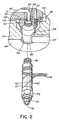
- Figure 1 shows a multi-nozzle injection molding apparatus or system wherein a number of heated steel nozzles 10 are mounted in a mold 12 to convey melt from a melt passage 14 in an elongated heated steel melt distribution manifold 16 to gates 18, each of which lead to a cavity 20. While only a single heated nozzle 10 is shown for ease of illustration, normally this type of apparatus will have a larger number of heated nozzles 10 extending forwardly in the mold from the heated elongated melt distribution manifold 16. Similarly, while the mold 12 can have a greater number of plates depending upon the application, in this case, only a rear back plate 22 and a manifold plate 24 secured together by bolts 25, as well as cavity plate 26 and a core plate 28 are shown for ease of illustration.
- the melt distribution manifold 16 has a heated inlet portion 30 which is surrounded by a locating ring 32 secured to the top clamp plate 22 by screws 34.
- the melt distribution manifold 16 is heated by an integral electrical heating element 36 and the surrounding mold 12 is cooled by pumping a cooling fluid such as water through cooling channels 38.
- the melt distribution manifold 16 is mounted between the rear back plate 22 and the manifold plate 24 by a central manifold locator 40 and a number of pressure discs 42 to provide an insulative air space 44 between the heated melt distribution manifold 16 and the surrounding cooled mold 12.
- Each heated nozzle 10 has a threaded rear end 46 which screws into a threaded seat or socket 48 in a mounting base 50 according to the invention.
- the mounting base 50 is secured by screws 52 extending through holes 58 through the melt distribution manifold 16 with its rear end 54 abutting against the front face 56 of the melt distribution manifold 16.
- Each heated nozzle 10 extends from the mounting base 50 forwardly through an opening 60 through the manifold plate 24 into an opening 62 in the cavity plate 26 extending to one of the gates 18 leading to a cavity 20.
- Each of the mounting bases 50 has a forwardly extending circular flange portion 64 which is received in a circular seat 66 extending around the opening 60 in the manifold plate 24 to locate the rear end 46 of the heated nozzle 10.
- the front end 68 of heated nozzle 10 is located by a two-piece nozzle seal 70 which is screwed into the front end 68 of the heated nozzle 10 and extends forwardly into a seat 72 in the cavity plate 26 to ensure the tip end 74 of the nozzle seal 70 is accurately aligned with the gate 18.
- the heated nozzles 10 are very accurately secured in place.
- Each heated nozzle 10 has a nut-like portion 76 which is engageable by a suitable tool (not shown) to tighten it into or loosen it out of the threaded seat or socket 48 in the mounting base 50.
- Each heated nozzle 10 also has wires 78 from an integral heating element 80 extending through a channel 82 in the front face 84 of the manifold plate 24.
- a thermocouple element 90 also extends through the channel 82 and the air space 88 and into the nozzle 10 to control the operating temperature. While the nozzles 10 are normally heated by an integral heating element 80, in applications for molding some materials it may not be necessary for the nozzles 10 to have heating elements.
- the melt passage 14 in the melt distribution manifold 16 extends outwardly from an inlet portion 94 in the inlet portion 30 of the melt distribution manifold 16 through a number of branches 96.
- Each branch 96 extends through an insert or plug 92 to an outlet 98 on the front face 56 of the melt distribution manifold 16.
- Each mounting base 50 has a melt bore 100 extending rearwardly therethrough from the threaded seat or socket 48 to its rear end 54.
- the melt bore 100 is the same size and is in alignment with one of the outlets 98 from the melt passage 92 in the melt distribution manifold 16.
- Each heated nozzle 10 also has a matching central melt bore 102 which is aligned with the melt bore 100 through the mounting base 50 and a melt bore 104 through the two-piece seal 70.
- the mold 12 is opened and the cavity plate 26 is removed by unscrewing bolts 106. As can be seen, this exposes the front ends 68 and the nut-like portions 76 of the heated nozzles 10.
- the provision of the mounting bases 50 with the threaded seats or sockets 48 according to the invention allow any of the heated nozzles 10 to be easily removed without removing the manifold plate 24 by unscrewing it from the socket 48 with a wrench and then cleaned or replaced by a new one.
- the system is assembled as shown. Electrical power is applied to the electrical heating elements 36, 80 in the melt distribution manifolds 16 and the heated nozzles 10 to heat the melt distribution manifolds 16 and the heated nozzles 10 to a predetermined operating temperature. Pressurized melt is then applied from a molding machine (not shown) to the inlet portion 94 of the melt passage 92 according to a predetermined injection cycle. The melt flows through the heated nozzle 10, mounting bases 50, and gates 18 into the cavity or cavities 20. After-the cavity 20 is filled and a suitable packing and cooling period has expired, infection pressure is released. The mold 12 is then opened to eject the molded product. After ejection, the mold 12 is closed and the cycle is repeated continuously every 15 to 30 seconds with a frequency depending upon the wall thickness and the number and size of the cavities 20 and the exact material being molded.
- the hot runner injection molding apparatus having the heated nozzles 10 screwed into threaded seats or sockets 48 in mounting bases 50 adjacent the melt distribution manifold 16 has been given with respect to a preferred embodiment, it will be evident that various modifications are possible without departing from the scope of the invention as understood by those skilled in the art and as defined in the following claims.
- the mounting bases 50 may be secured in place adjacent the melt distribution manifold 16 by means other than screws 52.
Landscapes
- Engineering & Computer Science (AREA)
- Manufacturing & Machinery (AREA)
- Mechanical Engineering (AREA)
- Moulds For Moulding Plastics Or The Like (AREA)
- Injection Moulding Of Plastics Or The Like (AREA)
- Dowels (AREA)
- Pens And Brushes (AREA)
Priority Applications (1)
| Application Number | Priority Date | Filing Date | Title |
|---|---|---|---|
| EP03019927A EP1369217B1 (en) | 1998-09-30 | 1999-09-30 | Injection molding nozzle screwed into mounting base |
Applications Claiming Priority (3)
| Application Number | Priority Date | Filing Date | Title |
|---|---|---|---|
| CA002248553A CA2248553A1 (en) | 1998-09-30 | 1998-09-30 | Injection molding nozzle screwed into mounting base |
| CA2248553 | 1998-09-30 | ||
| PCT/CA1999/000908 WO2000018559A1 (en) | 1998-09-30 | 1999-09-30 | Injection molding nozzle screwed into mounting base |
Related Child Applications (1)
| Application Number | Title | Priority Date | Filing Date |
|---|---|---|---|
| EP03019927A Division EP1369217B1 (en) | 1998-09-30 | 1999-09-30 | Injection molding nozzle screwed into mounting base |
Publications (2)
| Publication Number | Publication Date |
|---|---|
| EP1117520A1 EP1117520A1 (en) | 2001-07-25 |
| EP1117520B1 true EP1117520B1 (en) | 2004-11-24 |
Family
ID=4162855
Family Applications (2)
| Application Number | Title | Priority Date | Filing Date |
|---|---|---|---|
| EP03019927A Expired - Lifetime EP1369217B1 (en) | 1998-09-30 | 1999-09-30 | Injection molding nozzle screwed into mounting base |
| EP99945820A Expired - Lifetime EP1117520B1 (en) | 1998-09-30 | 1999-09-30 | Injection molding nozzle screwed into mounting base |
Family Applications Before (1)
| Application Number | Title | Priority Date | Filing Date |
|---|---|---|---|
| EP03019927A Expired - Lifetime EP1369217B1 (en) | 1998-09-30 | 1999-09-30 | Injection molding nozzle screwed into mounting base |
Country Status (9)
| Country | Link |
|---|---|
| US (2) | US6162043A (ko) |
| EP (2) | EP1369217B1 (ko) |
| JP (1) | JP2002525221A (ko) |
| KR (1) | KR100688435B1 (ko) |
| AT (1) | ATE283159T1 (ko) |
| AU (1) | AU758493B2 (ko) |
| CA (1) | CA2248553A1 (ko) |
| DE (2) | DE69939882D1 (ko) |
| WO (1) | WO2000018559A1 (ko) |
Families Citing this family (19)
| Publication number | Priority date | Publication date | Assignee | Title |
|---|---|---|---|---|
| IT248160Y1 (it) * | 1999-12-28 | 2002-12-10 | Sipa Spa | Stampi di iniezione perfezionati. |
| KR100548865B1 (ko) * | 2001-02-28 | 2006-02-02 | 허스키 인젝션 몰딩 시스템즈 리미티드 | 착탈식 노즐 본체 및 방법 |
| US6890473B2 (en) * | 2002-09-03 | 2005-05-10 | Mold-Masters Limited | Alignment collar for a nozzle |
| US20040258795A1 (en) * | 2003-06-23 | 2004-12-23 | Hans Guenther | Injection molding nozzle with separate nozzle flange |
| US7381050B2 (en) | 2004-10-20 | 2008-06-03 | Mold-Masters (2007) Limited | Snap on flange for injection molding nozzle |
| US7314367B2 (en) * | 2005-02-25 | 2008-01-01 | Mold-Masters (2007) Limited | Hot runner nozzle collar for an injection molding apparatus |
| EP2042290B1 (en) * | 2005-04-07 | 2013-09-25 | Mold-Masters (2007) Limited | Injection molding apparatus |
| ITTO20050611A1 (it) * | 2005-09-09 | 2007-03-10 | Thermoplay Spa | Commutatore del flusso di materiale plastico fuso in una piastrra calda per lo stampaggio ad iniezione |
| US7300275B2 (en) * | 2005-10-26 | 2007-11-27 | Panos Trakas | Multi-point nozzle assembly |
| US7890896B2 (en) * | 2005-11-18 | 2011-02-15 | Synopsys, Inc. | Method and apparatus for distinguishing combinational designs |
| US7462031B2 (en) * | 2005-11-25 | 2008-12-09 | Mold-Masters (2007) Limited | Injection molding nozzle with recessed terminal |
| DE102006026580A1 (de) * | 2006-06-08 | 2007-12-13 | Günther Heisskanaltechnik Gmbh | Spritzgussdüse, insbesondere Heißkanaldüse, zur Anordnung in einem Spritzgießwerkzeug |
| DE102006026579A1 (de) * | 2006-06-08 | 2007-12-13 | Günther Heisskanaltechnik Gmbh | Spritzgussdüse, insbesondere Heißkanaldüse, zur Anordnung in einem Spritzgießwerkzeug |
| US7699600B2 (en) * | 2008-01-30 | 2010-04-20 | Husky Injection Molding Systems Ltd. | Flexible plate slot for a hot runner injection molding system |
| US8277213B2 (en) | 2010-12-17 | 2012-10-02 | Dme Company Llc | Apparatus for injection molding |
| BE1022045B1 (nl) | 2011-02-03 | 2016-02-09 | Resilux | Spuitgietinrichting voor het vervaardigen van holle voorwerpen, i.h.b. kunststofvoorvormelingen, resp.-behouders, en werkwijze hiervoor |
| US8287272B1 (en) * | 2011-03-31 | 2012-10-16 | Dme Company Llc | Injection molding apparatus having a nozzle retaining clip |
| DE102011051292A1 (de) | 2011-06-23 | 2012-12-27 | Günther Heisskanaltechnik Gmbh | Materialrohr für eine Spritzgießdüse, Spritzgießdüse, Spritzgießdüsenanordnung und Spritzgießdüsenmontagewerkzeug |
| CN104772860B (zh) | 2013-12-11 | 2017-10-13 | 马斯特模具(2007)有限公司 | 插入式热浇道系统 |
Family Cites Families (27)
| Publication number | Priority date | Publication date | Assignee | Title |
|---|---|---|---|---|
| JPS51125160A (en) * | 1974-06-27 | 1976-11-01 | Saito Kouki Kk | Automatically opening or closing valve gate for plastic injection molding |
| US4268240A (en) * | 1978-01-06 | 1981-05-19 | Husky Injection Molding Systems | Actuating mechanism for gate valve of injection nozzle |
| US4292018A (en) * | 1980-05-21 | 1981-09-29 | Beatrice Foods Co. | Double nozzle block |
| JPS6395923A (ja) * | 1986-10-13 | 1988-04-26 | Sony Corp | ホツトランナ−式射出成型装置 |
| CA1267514A (en) * | 1987-07-15 | 1990-04-10 | Jobst Ulrich Gellert | Coated injection molding nozzle and method |
| DE4028660A1 (de) * | 1990-09-10 | 1992-03-26 | Incoe International Inc Zweign | Heisskanal-verteilersystem |
| JP2967574B2 (ja) | 1990-11-16 | 1999-10-25 | 株式会社日立製作所 | 冷凍装置 |
| CA2073710C (en) * | 1992-07-13 | 2000-03-28 | Jobst Ulrich Gellert | Injection molding nozzle with removable forward member |
| CA2083413C (en) * | 1992-11-19 | 2000-07-04 | Jobst Ulrich Gellert | Injection molding nozzle with partially unheated heating element |
| US5591366A (en) * | 1994-06-23 | 1997-01-07 | Husky Injection Molding Systems Ltd. | Injection molding heater including circuit breaking means |
| CA2127211C (en) * | 1994-06-30 | 2004-09-21 | Jobst Ulrich Gellert | Injection molding nozzle with removable collar portion |
| US5533882A (en) | 1994-11-29 | 1996-07-09 | Husky Injection Molding Systems Ltd. | Hot runner valve gated system |
| CA2137702C (en) * | 1994-12-07 | 2004-11-02 | Jobst Ulrich Gellert | Injection molding nozzle with separable core and one-piece collar |
| FR2734756B1 (fr) | 1995-05-30 | 1997-09-12 | Atek Dev | Ensemble d'injection pour un moule d'injection de matiere plastique ainsi qu'un procede de realisation d'un tel ensemble |
| US5820900A (en) * | 1996-08-21 | 1998-10-13 | Mcgrevy; Alan N. | Heating device for an injection mold apparatus |
| US5804228A (en) | 1996-08-21 | 1998-09-08 | Caco Pacific Corporation | Minimum vestige nozzle assembly for plastics injection molding |
| US6309207B1 (en) | 1998-06-10 | 2001-10-30 | Husky Injection Molding Systems Ltd. | Injection molding nozzle assembly |
| US6062846A (en) | 1997-06-13 | 2000-05-16 | Husky Injection Molding Systems, Ltd. | Injection molding nozzle assembly |
| US20010011415A1 (en) | 1997-06-13 | 2001-08-09 | Jacek Kalemba | Injection molding nozzle assembly |
| CA2219260C (en) * | 1997-10-23 | 2006-12-05 | Mold-Masters Limited | Injection molding apparatus having inter-manifold melt transfer bushings |
| US6043466A (en) * | 1998-02-20 | 2000-03-28 | Husky Injection Molding Systems Ltd. | Hot runner heating clamp |
| CA2239349A1 (en) * | 1998-05-29 | 1999-11-29 | Denis Babin | Injection molding apparatus having nozzles with elongated mounting flanges |
| DE19848188A1 (de) | 1998-10-20 | 2000-04-27 | Incoe Int Inc | Düsen für Spritzgießanlagen |
| WO2000053388A1 (fr) | 1999-03-09 | 2000-09-14 | Shinko Sellbic Co., Ltd. | Unite a canaux chauffes et moule metallique a canaux chauffes |
| US6220851B1 (en) | 1999-04-19 | 2001-04-24 | Husky Injection Molding Systems Ltd. | Detachable nozzle body |
| KR100548865B1 (ko) | 2001-02-28 | 2006-02-02 | 허스키 인젝션 몰딩 시스템즈 리미티드 | 착탈식 노즐 본체 및 방법 |
| DE10151693C2 (de) | 2001-10-19 | 2003-10-23 | Incoe Int Inc | Komplettes Spritzseitenteil für eine Spritzgießmaschine und Verfahren zur Wartung des darin enthaltenen Heißkanal-Verteilersystems |
-
1998
- 1998-09-30 CA CA002248553A patent/CA2248553A1/en not_active Abandoned
- 1998-10-21 US US09/176,368 patent/US6162043A/en not_active Ceased
-
1999
- 1999-09-30 KR KR1020017004116A patent/KR100688435B1/ko active IP Right Grant
- 1999-09-30 EP EP03019927A patent/EP1369217B1/en not_active Expired - Lifetime
- 1999-09-30 EP EP99945820A patent/EP1117520B1/en not_active Expired - Lifetime
- 1999-09-30 AT AT99945820T patent/ATE283159T1/de not_active IP Right Cessation
- 1999-09-30 JP JP2000572066A patent/JP2002525221A/ja active Pending
- 1999-09-30 DE DE69939882T patent/DE69939882D1/de not_active Expired - Lifetime
- 1999-09-30 AU AU58459/99A patent/AU758493B2/en not_active Ceased
- 1999-09-30 WO PCT/CA1999/000908 patent/WO2000018559A1/en active IP Right Grant
- 1999-09-30 DE DE69922233T patent/DE69922233T2/de not_active Expired - Lifetime
-
2002
- 2002-12-19 US US10/323,869 patent/USRE38920E1/en not_active Expired - Lifetime
Also Published As
| Publication number | Publication date |
|---|---|
| US6162043A (en) | 2000-12-19 |
| DE69939882D1 (de) | 2008-12-18 |
| EP1369217A3 (en) | 2003-12-17 |
| KR20010079965A (ko) | 2001-08-22 |
| DE69922233D1 (de) | 2004-12-30 |
| USRE38920E1 (en) | 2005-12-13 |
| KR100688435B1 (ko) | 2007-03-09 |
| JP2002525221A (ja) | 2002-08-13 |
| EP1369217B1 (en) | 2008-11-05 |
| ATE283159T1 (de) | 2004-12-15 |
| DE69922233T2 (de) | 2005-12-01 |
| WO2000018559A1 (en) | 2000-04-06 |
| AU758493B2 (en) | 2003-03-20 |
| EP1117520A1 (en) | 2001-07-25 |
| AU5845999A (en) | 2000-04-17 |
| EP1369217A2 (en) | 2003-12-10 |
| CA2248553A1 (en) | 2000-03-30 |
Similar Documents
| Publication | Publication Date | Title |
|---|---|---|
| EP1117520B1 (en) | Injection molding nozzle screwed into mounting base | |
| CA2123360C (en) | Injection molding nozzle with two removable inserts | |
| CA2099334C (en) | Injection molding insert with melt inlet and pin aligned | |
| US5268184A (en) | Injection molding nozzle with removable forward member | |
| US5494433A (en) | Injection molding hot tip side gate seal having a circumferential rim | |
| EP0916470B1 (en) | Side gated injection molding apparatus with actuated manifold | |
| EP0743159B1 (en) | Side gated injection molding apparatus with radially mounted gate inserts | |
| CA2047461A1 (en) | Injection molding manifold with removable inserts | |
| EP0950494B1 (en) | Cylindrical injection molding manifold insert and method | |
| EP0778117B1 (en) | Injection molding nozzle manifold | |
| CA2127211C (en) | Injection molding nozzle with removable collar portion | |
| US5536165A (en) | Injection molding apparatus with nozzle advanceable to mount side gate seals | |
| EP0468485B1 (en) | A pre-wired injection molding assembly | |
| EP0960713B1 (en) | Injection molding apparatus having nozzles with elongated mounting flanges | |
| EP0633118B1 (en) | Two-piece injection molding nozzle seal | |
| EP0657269B1 (en) | Injection molding apparatus with perpendicular hot tip gates | |
| EP0743157B1 (en) | Injection molding apparatus with nozzle advanceable to mount side gate seals | |
| EP0743158B1 (en) | Injection molding hot tip side gate seal with circumferential rim | |
| US4795338A (en) | Mounting for injection molding nozzle | |
| EP0695618B1 (en) | Injection molding nozzle with collar having locating and retaining lug portions |
Legal Events
| Date | Code | Title | Description |
|---|---|---|---|
| PUAI | Public reference made under article 153(3) epc to a published international application that has entered the european phase |
Free format text: ORIGINAL CODE: 0009012 |
|
| 17P | Request for examination filed |
Effective date: 20010424 |
|
| AK | Designated contracting states |
Kind code of ref document: A1 Designated state(s): AT BE CH CY DE DK ES FI FR GB GR IE IT LI LU MC NL PT SE |
|
| GRAH | Despatch of communication of intention to grant a patent |
Free format text: ORIGINAL CODE: EPIDOS IGRA |
|
| GRAS | Grant fee paid |
Free format text: ORIGINAL CODE: EPIDOSNIGR3 |
|
| GRAA | (expected) grant |
Free format text: ORIGINAL CODE: 0009210 |
|
| AK | Designated contracting states |
Kind code of ref document: B1 Designated state(s): AT BE CH CY DE DK ES FI FR GB GR IE IT LI LU MC NL PT SE |
|
| PG25 | Lapsed in a contracting state [announced via postgrant information from national office to epo] |
Ref country code: NL Free format text: LAPSE BECAUSE OF FAILURE TO SUBMIT A TRANSLATION OF THE DESCRIPTION OR TO PAY THE FEE WITHIN THE PRESCRIBED TIME-LIMIT Effective date: 20041124 Ref country code: FI Free format text: LAPSE BECAUSE OF FAILURE TO SUBMIT A TRANSLATION OF THE DESCRIPTION OR TO PAY THE FEE WITHIN THE PRESCRIBED TIME-LIMIT Effective date: 20041124 Ref country code: ES Free format text: LAPSE BECAUSE OF FAILURE TO SUBMIT A TRANSLATION OF THE DESCRIPTION OR TO PAY THE FEE WITHIN THE PRESCRIBED TIME-LIMIT Effective date: 20041124 Ref country code: BE Free format text: LAPSE BECAUSE OF FAILURE TO SUBMIT A TRANSLATION OF THE DESCRIPTION OR TO PAY THE FEE WITHIN THE PRESCRIBED TIME-LIMIT Effective date: 20041124 Ref country code: AT Free format text: LAPSE BECAUSE OF FAILURE TO SUBMIT A TRANSLATION OF THE DESCRIPTION OR TO PAY THE FEE WITHIN THE PRESCRIBED TIME-LIMIT Effective date: 20041124 |
|
| REG | Reference to a national code |
Ref country code: GB Ref legal event code: FG4D |
|
| REG | Reference to a national code |
Ref country code: CH Ref legal event code: EP |
|
| REF | Corresponds to: |
Ref document number: 69922233 Country of ref document: DE Date of ref document: 20041230 Kind code of ref document: P |
|
| REG | Reference to a national code |
Ref country code: IE Ref legal event code: FG4D |
|
| PG25 | Lapsed in a contracting state [announced via postgrant information from national office to epo] |
Ref country code: SE Free format text: LAPSE BECAUSE OF FAILURE TO SUBMIT A TRANSLATION OF THE DESCRIPTION OR TO PAY THE FEE WITHIN THE PRESCRIBED TIME-LIMIT Effective date: 20050224 Ref country code: GR Free format text: LAPSE BECAUSE OF FAILURE TO SUBMIT A TRANSLATION OF THE DESCRIPTION OR TO PAY THE FEE WITHIN THE PRESCRIBED TIME-LIMIT Effective date: 20050224 Ref country code: DK Free format text: LAPSE BECAUSE OF FAILURE TO SUBMIT A TRANSLATION OF THE DESCRIPTION OR TO PAY THE FEE WITHIN THE PRESCRIBED TIME-LIMIT Effective date: 20050224 |
|
| REG | Reference to a national code |
Ref country code: CH Ref legal event code: NV Representative=s name: PATENTANWALTSBUERO JEAN HUNZIKER |
|
| NLV1 | Nl: lapsed or annulled due to failure to fulfill the requirements of art. 29p and 29m of the patents act | ||
| PGFP | Annual fee paid to national office [announced via postgrant information from national office to epo] |
Ref country code: GB Payment date: 20050825 Year of fee payment: 7 |
|
| PG25 | Lapsed in a contracting state [announced via postgrant information from national office to epo] |
Ref country code: MC Free format text: LAPSE BECAUSE OF NON-PAYMENT OF DUE FEES Effective date: 20050930 Ref country code: IE Free format text: LAPSE BECAUSE OF NON-PAYMENT OF DUE FEES Effective date: 20050930 Ref country code: CY Free format text: LAPSE BECAUSE OF FAILURE TO SUBMIT A TRANSLATION OF THE DESCRIPTION OR TO PAY THE FEE WITHIN THE PRESCRIBED TIME-LIMIT Effective date: 20050930 |
|
| PLBE | No opposition filed within time limit |
Free format text: ORIGINAL CODE: 0009261 |
|
| STAA | Information on the status of an ep patent application or granted ep patent |
Free format text: STATUS: NO OPPOSITION FILED WITHIN TIME LIMIT |
|
| 26N | No opposition filed |
Effective date: 20050825 |
|
| ET | Fr: translation filed | ||
| REG | Reference to a national code |
Ref country code: IE Ref legal event code: MM4A |
|
| GBPC | Gb: european patent ceased through non-payment of renewal fee |
Effective date: 20060930 |
|
| PG25 | Lapsed in a contracting state [announced via postgrant information from national office to epo] |
Ref country code: GB Free format text: LAPSE BECAUSE OF NON-PAYMENT OF DUE FEES Effective date: 20060930 |
|
| PG25 | Lapsed in a contracting state [announced via postgrant information from national office to epo] |
Ref country code: PT Free format text: LAPSE BECAUSE OF NON-PAYMENT OF DUE FEES Effective date: 20050424 |
|
| REG | Reference to a national code |
Ref country code: CH Ref legal event code: PUE Owner name: MOLD-MASTERS (2007) LIMITED Free format text: GELLERT, JOBST ULRICH#7A PRINCE STREET#GEORGETOWN ONTARIO L7G 2X1 (CA) -TRANSFER TO- MOLD-MASTERS (2007) LIMITED#233 ARMSTRONG AVENUE#GEORGETOWN ON L7G4X5 (CA) |
|
| PGFP | Annual fee paid to national office [announced via postgrant information from national office to epo] |
Ref country code: LU Payment date: 20080828 Year of fee payment: 10 Ref country code: CH Payment date: 20080826 Year of fee payment: 10 |
|
| PGFP | Annual fee paid to national office [announced via postgrant information from national office to epo] |
Ref country code: IT Payment date: 20080913 Year of fee payment: 10 |
|
| REG | Reference to a national code |
Ref country code: FR Ref legal event code: TP |
|
| REG | Reference to a national code |
Ref country code: CH Ref legal event code: PL |
|
| PG25 | Lapsed in a contracting state [announced via postgrant information from national office to epo] |
Ref country code: LI Free format text: LAPSE BECAUSE OF NON-PAYMENT OF DUE FEES Effective date: 20090930 Ref country code: CH Free format text: LAPSE BECAUSE OF NON-PAYMENT OF DUE FEES Effective date: 20090930 |
|
| PG25 | Lapsed in a contracting state [announced via postgrant information from national office to epo] |
Ref country code: IT Free format text: LAPSE BECAUSE OF NON-PAYMENT OF DUE FEES Effective date: 20090930 |
|
| PG25 | Lapsed in a contracting state [announced via postgrant information from national office to epo] |
Ref country code: LU Free format text: LAPSE BECAUSE OF NON-PAYMENT OF DUE FEES Effective date: 20090930 |
|
| REG | Reference to a national code |
Ref country code: FR Ref legal event code: PLFP Year of fee payment: 18 |
|
| REG | Reference to a national code |
Ref country code: FR Ref legal event code: PLFP Year of fee payment: 19 |
|
| REG | Reference to a national code |
Ref country code: FR Ref legal event code: PLFP Year of fee payment: 20 |
|
| PGFP | Annual fee paid to national office [announced via postgrant information from national office to epo] |
Ref country code: DE Payment date: 20180821 Year of fee payment: 20 Ref country code: FR Payment date: 20180822 Year of fee payment: 20 |
|
| REG | Reference to a national code |
Ref country code: DE Ref legal event code: R071 Ref document number: 69922233 Country of ref document: DE |