BACKGROUND OF THE INVENTION
1. Field of the Invention
The present invention relates to a light-emitting system.
More particularly, it relates to improvement in a
light-transmissible layer of a light-emitting system using a
Group III nitride compound light-emitting device (hereinafter
merely referred to as "light-emitting device") such as an LED
as a light source.
The present application is based on Japanese Patent
Application No. 2000-2748, which is incorporated herein by
reference.
2. Description of the Related Art
In a general light-emitting system, an LED is mounted
on a cup portion of a mount lead and connected to an inner lead
through an electrically conductive wire, as described in
JP-A-59-54277. The LED, together with the electrically
conductive wire, a part of the mount lead and a part of the
inner lead, is covered with a sealing member made of a
light-transmissible resin. Such a configuration is employed
in an LED made of Group III nitride compound semiconductors.
For example, see Japanese Patent No. 2927279.
In the light-emitting system having such a configuration
as described above, the sealing member is generally made of
a transparent epoxy resin. JP-A-10-215004 has proposed that
an epoxy resin using a curing catalyst for cationic
polymerization is used as the sealing member in order to achieve
prevention of deformation/destruction; preventionofelectrode
corrosion; facilitation of assembling; reduction of cost; and
so on. The proposal has shown the case where any one of a
bisphenol-A type epoxy resin, a bisphenol-F type epoxy resin
and an alicyclic epoxy resin is used as the epoxy resin or a
combination thereof is used as the epoxy resin.
Because JP-A-10-215004 relates to a light source for an
image scanner, it is conceived that the LED to be used in
JP-A-10-215004 is constituted by any other materials than the
Group III nitride compound semiconductors. Although
JP-A-10-215004 has described that an amine type epoxy resin
is discolored under environment of use in JP-A-10-215004, it
is a matter of common knowledge that weather resistance is
worsened when amine is used as a curing catalyst, that is, this
phenomenon is not limited when the amine type epoxy resin is
used as a member for sealing an LED used as a light source.
Japanese Patent No. 2927279 discloses an epoxy resin as
an example of a sealing member.
An epoxy resin is generally used as a member for sealing
an LED as described above. However, there has been no specific
discussion about what deteriorating phenomenon occurs when the
epoxy resin is used as a member for sealing a Group III nitride
compound semiconductor light-emitting device which outputs
short-wave light.
SUMMARY OF THE INVENTION
An object of the present invention is to provide an epoxy
resin adapted to a member for sealing a light-emitting device
made of Group III nitride compound semiconductors in pursuit
of characteristic of the epoxy resin used as the sealing member.
The inventors of the present invention have eagerly
examined the relationship between a light-emitting device made
of group III nitride compound semiconductors and an epoxy resin.
As a result, the inventors have conceived an invention configured
as follows. That is, a light-emittingsystemcomprises: a Group
III nitride compound semiconductor light-emitting device; and
a light-transmissible layer surrounding the light-emitting
device, wherein the light-transmissible layer is made of an
alicyclic epoxy resin.
The light-emitting device made of Group III nitride
compound semiconductors emits light with a short wavelength.
Because such light with a short wavelength has high energy,
deterioration (yellowing) of the epoxy resin is accelerated.
Hence, when the epoxy resin is of an aromatic type, the epoxy
resin satisfies physical properties such as curing speed,
hardness, etc. of a sealing member but it is difficult to obtain
sufficient durability because the double bondof the epoxy resin
serves as an active seed so that the epoxy resin is affected
by light emitted from the light-emitting device. For example,
there is a possibility that a bisphenol-A type epoxy resin is
denatured to quinoid (brown) by light. On the other hand, an
aliphatic epoxy resin has sufficient durability against light
but is unsuitable as a sealing member in terms of physical
properties such as remarkably high curing speed, large
distortion after curing, etc.
In this respect, an alicyclic epoxy resin is hardly
deteriorated (yellowed) even in the case where the alicyclic
epoxy resin is disposed in proximity of the Group III nitride
compound semiconductor light-emitting device because the
alicyclic epoxy resin has no double bond as an active seed.
Also from the point of view of physical properties, the alicyclic
epoxy resin is used sufficiently as a member for sealing the
light-emitting device though the alicyclic epoxy resin does
not amount, in physical properties, to the aromatic epoxy resin.
As a result of eager investigation by the inventors of
the present invention, it has been found that an epoxy resin
composition proposed in JP-A-11-199645 is used preferably as
the aforementioned alicyclic epoxy resin. The proposed epoxy
resin is a hydrogenated epoxy resin prepared by hydrogenation
of an aromatic epoxy resin and having an alicyclic hydrogenating
ratio of not lower than 85 %, an epoxy group loss ratio of not
higher than 20 % and a total chlorine content of nor larger
than 0.3 % by weight.
In this paragraph, related matters will be quoted from
JP-A-11-199645 in order to clarify the disclosure of the
invention.
Features and advantages of the invention will be evident
from the following detailed description of the preferred
embodiments described in conjunction with the attached
drawings.
BRIEF DESCRIPTION OF THE DRAWINGS
In the accompanying drawings:
DETAILED DESCRIPTION OF THE PREFERRED EMBODIMENTS
The present invention will be described below in detail.
Component (A): Hydrogenated Epoxy Resin
The hydrogenated epoxy resin as component (A) in the
present invention is an epoxy resin prepared by a hydrogenating
reaction of an aromatic epoxy resin and having an aromatic ring
hydrogenating ratio of not lower than 85 %, an epoxy group loss
ratio of not higher than 20 % and a total chlorine content of
not larger than 0.3 % by weight. The hydrogenating ratio of
aromatic rings in the epoxy resin is a ratio by which the aromatic
rings are changed to aliphatic rings. The aromatic ring
hydrogenating ratio can be measured by nuclear magnetic
resonance analysis. The epoxy group loss ratio is a ratio by
which epoxy groups are hydro-cracked. The epoxy group loss
ratio can be measured by titration of perchloric acid. The
total chlorine content is the total amount of organic chlorine
and inorganic chlorine contained in the epoxy resin. The total
chlorine content can be measured by titration of silver nitrate
after a reaction of biphenyl sodium with chlorine in the epoxy
resin.
When the hydrogenated epoxy resin as component (A) is
usedasamaterial for sealing electronicparts, the hydrogenated
epoxy resin preferably has a hydrolytic chlorine content of
not larger than 0.1 % by weight. If the aromatic ring
hydrogenating ratio is lower than 85 %, it is undesirable that
the weather resistance of the cured epoxy resin is lowered
extremely. If the epoxy group loss ratio is higher than 20 %,
it is undesirable that the heat resistance of the cured epoxy
resin is lowered extremely. If the total chlorine content is
larger than 0.3 % by weight, the epoxy resin is unsuitable as
an epoxy resin for electric/electronic materials because the
moisture resistance, high-temperature electriccharacteristic
and weather resistance of the epoxy resin are lowered.
(Method for Producing Hydrogenated Epoxy Resin)
The hydrogenated epoxy resin as component (A) in the
present invention is prepared by a selective hydrogenating
reaction of an aromatic epoxy resin under pressure and under
presence of a catalyst. Examples of the aromatic epoxy resin
may include: bisphenol epoxy resins such as bisphenol-A
diglycidyl ether, bisphenol-F diglycidyl ether, bisphenol-S
diglycidyl ether, etc.; novolac epoxy resins such as phenol
novolac epoxy, cresol novolac epoxy, hydroxybenzaldehyde
phenol novolac epoxy, etc.; and multifunctional epoxy resins
such as tetrahydroxyphenylmethane glycidyl ether,
tetrahydroxybenzophenone glycidyl ether, epoxydized polyvinyl
phenol, etc.
Among these materials, bisphenol-A epoxy resins and
novolac epoxy resins represented by the general formula (1)
are used preferably from the point of view of low chlorine
content.
in which each of R1, R2 and R3 shows a hydrogen atom or an alkyl
group having 1 to 4 carbon atoms,
n shows a numerical value
of from 0 to 10, and Z shows a hydrogen atom or the formula:
in which each of R1, R2 and R3 shows a hydrogen atom or an alkyl
group having 1 to 4 carbon atoms.
For the purpose of use particularly requiring good balance
between heat resistance and moisture resistance, there are
preferably used hydrogenated bisphenol-A epoxy resins having
a viscosity of not higher than 2.5 Pa·s at 25°C when measured
by a rotaviscometer and novolac epoxy resins represented by
the general formula (1), especially epoxy resins produced by
hydrogenation of aromatic epoxy resins each having an hydrogen
atom or a methyl group as each of R1, R2 and R3 and having an
epoxy equivalent amount in a range of from 150 to 230.
The method for producing the hydrogenated epoxy resin
as component (A) in the present invention is as follows.
Aromatic rings are selectively hydrogenated by use of an ether
type organic solvent such as tetrahydrofuran, dioxane, etc.
under presence of a catalyst composed of graphite (hexagonal
graphite) and rhodium or ruthenium carried by the graphite.
A carrier having a surface area in a range of from 10 m2/g to
400 m2/g inclusively is used as the graphite. The reaction is
performed under pressure in a range of from 1 to 30 Mpa at a
temperature in a range of from 30 to 150°C for a reaction time
in a range of from 1 to 20 hours . After the reaction is completed,
the catalyst is removed by filtration and the ether type organic
solvent is fractionated under decompression till the ether type
organic solvent is substantially eliminated. Thus, a
hydrogenated epoxy resin is obtained.
Component (B): Epoxy Resin Curing Agent
The hydrogenated epoxy resin as component (A) in the
present invention can be cured by use of an epoxy resin curing
agent. An available epoxy resin curing agent is used as the
epoxy resin curing agent which is component (B) . Examples of
the epoxy resin curing agent may include as follows.
These epoxy resin curing agents may be used singly or
in combination.
The aforementioned epoxy resin curing agent is preferably
used so that the aromatic ring content is not larger than 10 %
by weight with respect to the total amount of the curing agent.
If the aromatic ring content is larger than 10 % by weight,
the weather resistance of the cured epoxy resin is undesirably
lowered. The hydrogenated epoxy resin as component (A) and
the epoxy resin curing agent as component (B) are mixed with
each other in proportion of 0.01 to 200 parts by weight,
preferably 0.1 to 150 parts by weight of the epoxy resin curing
agent as component (B) with respect to 100 parts by weight of
the hydrogenated epoxy resin as component (A) . If proportion
is out of the aforementioned range, the balance between heat
resistance and moisture resistance of the cured epoxy resin
is worsened undesirably.
(Optional Components)
The following components may be added to the epoxy resin
composition in the present invention as occasion demands.
When the epoxy resin is viewed as a member for sealing
the Group III nitride compound semiconductor light-emitting
device, it is conceived that yellowing is caused by the influence
of the curing agent as well as the double bond in molecules.
As described above, yellowing is accelerated when an amine
type curing agent is used. It is conceived that the acceleration
of yellowing is caused diazo formed by denaturation of amine.
In an acid anhydride curing agent, the carbonyl group contained
in the curing agent serves as an active seed to thereby cause
yellowing of the epoxy resin.
Therefore, the inventors of the present invention
determine use of a cationic polymerization catalyst. When the
cationic polymerization catalyst is used, epoxy rings are
cleaved. As a result, epoxy groups react with each other to
thereby form ether bonds. Because the cationic polymerization
catalyst generally has neither active seed nor functional seed,
the catalyst is inactive to light emitted from the Group III
nitride compound semiconductor light-emitting device even in
the case where the catalyst remains in the epoxy resin.
A known catalyst such as sulfonium salt, ammonium salt,
phosphonium salt, onium salt, silanol-aluminum complex, etc.
may be used as the cationic polymerization catalyst. For
example, cationic polymerization catalysts disclosed in
Japanese Patent No. 2875479, JP-A-2-289611 and JP-A-11-29609
may be used.
It is more preferable to use a sulfonium salt type cationic
polymerization catalyst.
Although the amount of the cationic polymerization
catalyst depends on the performance of the catalyst, it is
preferable that 0.1 to 5.0 % by weight of the catalyst is mixed
with the epoxy resin. More preferably, 0.5 to 1.5 % by weight
of the catalyst is mixed.
The epoxy resin prepared as described above forms a
light-transmissible sealing member surrounding the
light-emitting device. The shape of the sealing member is not
particularly limited but the sealingmember is preferably shaped
like an artillery shell to obtain a lens effect. All portions
of the sealing member need not be formed from the epoxy resin
according to the present invention. A circumferential portion
of the light-emitting device where deterioration advances most
rapidly may be formed from the epoxy resin according to the
present invention but the other portion may be formed from
another light-transmissible material.
The Group III nitride compound semiconductor
light-emitting device to be used in the light-emitting system
according to the present invention is adapted to a device
emitting light with a relatively short wavelength inclusive
of a peak wavelength of not larger than 550 nm. More preferably,
the peak wavelength is selected to be in a range of from 360
to 400 nm. A light emitting diode or a laser diode may be used
as the light emitting device. A homostructure, a
heterostructure or a double heterostructure having an MIS
junction, a PIN junction or a p-n junction may be used as the
configuration of the light-emitting device. A quantum well
structure (single quantum well structure or multiple quantum
well structure) may be also used as the light-emitting device.
Incidentally, Group III nitride compound semiconductors
are represented by the general formula AlXGaYIn1-X-YN (0≦X≦
1, 0≦Y≦1, 0≦X+Y≦1), which includes so-called binary
compounds such as AlN, GaN and InN, and so-called ternary
compounds such as AlXGa1-XN, AlXIn1-XN and GaXIn1-XN (0≦X≦ 1 each).
The Group III elements may be partially replaced by boron (B),
thallium (T1), etc. The nitrogen (N) may be partially replaced
by phosphorus (P), arsenic (As), antimony (Sb), bismuth (Bi),
etc. Each of the group III nitride compound semiconductors
may contain any optional dopant. Si, Ge, Se, Te, C, etc. may
be used as n-type impurities. Mg, Zn, Be, Ca, Sr, Ba, etc.
may be used as p-type impurities. Incidentally, after doped
with p-type impurities, the Group III nitride compound
semiconductor may be subjected to electron beam irradiation,
plasma irradiation or heat due to a furnace. The method of
forming the group III nitride compound semiconductor is not
particularly limited but may be formed by a metal organic
chemical vapor deposition method (MOCVD method) or by a known
method such as a molecular beam epitaxy method (MBE method),
a halide vapor phase epitaxy method (HVPE method), a sputtering
method, an ion-plating method, an electron shower method, or
the like. The substrate is not particularly limited so long
as a Group III nitride compound semiconductor can be grown on
the substrate. Examples of the substrate material may include
sapphire, spinel, silicon, silicon carbide, zinc oxide, gallium
phosphide, gallium arsenide, magnesium oxide, manganese oxide,
Group III nitride compound semiconductor single crystal, etc.
According to the examination by the present inventors, it is
preferable to use sapphire, especially face a thereof, as the
substrate. To form a Group III nitride compound semiconductor
with good crystallinity, a buffer layer is preferably formed
on the sapphire substrate so that lattice mismatching therewith
is corrected. A quarternary compound semiconductor
represented by AlXGaYIn1-X-YN (0<X<1, 0<Y<1, 0<X+Y<1), a ternary
compound semiconductor represented by AlXGa1-XN (0<X<1) or AlN,
GaN or InN can be used as the buffer layer.
Various additives may be mixed with the epoxy resin
according to the present invention. Examples of the additives
may include reinforcing agents, fillers, colorants, pigments,
fire retardants, etc. as described above.
The following fluorescent substances may be added as
additives. That is, at least one fluorescent substance
selected from the group consisting of ZnS:Cu, Au, Al; ZnS:Cu,
Al; ZnS:Cu; ZnS:Mn; ZnS:Eu; YVO,:Eu; YVO4:Ce; Y2O2S:Eu; and
Y2O2S:Ce is used. ZnS:Cu, Au, Al is a ZnS photoluminescence
fluorescent substance containing ZnS as a parent body activated
by Cu, Au and Al. ZnS:Cu, Al; ZnS:Cu; ZnS:Mn and ZnS:Eu are
photoluminescence fluorescent substances containing ZnS as a
parent body activated by Cu and Al, Cu, Mn, and Eu, respectively.
Similarly, YVO4:Eu and YVO4:Ce are fluorescent substances
containing YVO4 as a parent body activated by Eu and Ce
respectively. Y2O2S:Eu and Y2O2S:Ce are fluorescent substances
containing Y2O2 as a parent body activated by Eu and Ce
respectively. These fluorescent substances have absorption
spectra for a range of from blue light to green light. Each
of the fluorescent substances emits light with a wavelength
longer than the excitation wavelength.
Among the above fluorescent substances, ZnS:Eu, YVO4:Ce
and Y2O2S : Ce have a long emission wavelength for excitation light
in a range of from blue light to green light compared with the
other fluorescent substances. That is, the color of light
emitted from these fluorescent substances is redder. As a
result, the color of light obtained by mixture of light emitted
from the fluorescent substances and light emitted from the
light-emittingdeviceas a primarylightsourceisneartowhite.
To obtain the color of emitted light nearer to white as described
above, at least one fluorescent substance is preferably selected
from the group consisting of ZnS:Eu, YVO4:Ce and Y2O2S:Ce.
Alternatively, CaS:Eu can be also used as the fluorescent
substance. According to the fluorescent substance, red
fluorescence is obtained.
Further, an yttrium-aluminum-garnet fluorescent
substance activated by cerium may be used as described in
Japanese Patent No. 2927279. Activation by cerium may be
omitted. In the yttrium-aluminum-garnet fluorescent
substance, yttrium may be partially or wholly replaced by at
least one element selected from the group consisting of Lu,
Sc, La, Gd, and Sm or aluminum may be partially or wholly replaced
by either or both of Ga and In. More specifically,
(RE1-xSmx)3(AlyGa1-y)5O12:Ce (0 ≦x<1, 0≦y<1, RE being at least one
selected from the group consisting of Y and Gd) may be used.
In this case, it is preferable that light emitted from the Group
III nitride compound semiconductor light-emitting device has
a peak wavelength in a range of from 400 to 530 nm.
The present invention will be described below more in
detail on the basis of Examples.
An LED with a peak wavelength of 382 nm provided by TOYODA
GOSEI Co., Ltd. (Applicant) was used as a light-emitting device
made of Group III nitride compound semiconductors. The
configuration of the LED was as follows.
| Layer | Composition | Dopant | (Thickness) |
| p-type clad layer | n-GaN | Si | (0.3 µm) |
| Light-emitting layer | Superlattice | structure |
| Quantum well layer | In0.07Ga0.93N | | (3.5 nm) |
| Barrier layer | GaN | | (3.5 nm) |
| Number of repeated quantum well and barrier layers: 1 to 10 |
| n-type clad layer | p-GaN | Mg | (4 µm) |
| Buffer layer | AlN | | (15 nm) |
| Substrate | Sapphire | | (300 µm) |
The p-type clad layer, the light-emitting layer and the
n-type clad layer were partially etched to thereby form a bonding
pad for the n-type clad layer. A transparent electrode was
formed on the upper surface of the p-type clad layer. A bonding
pad was formed thereon.
The LED configured as described above was formed by a
known MOCVD method.
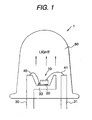
As shown in Fig. 1, an LED chip 10 was fixed on a cup
portion 33 of a mount lead 30 through silver paste 20. The
n-type electrode of the LED chip 10 was electrically connected
to the mount lead 30 through an electrically conductive wire
40. The p-type electrode of the LED chip 10 was electrically
connected to an inner lead 31 through an electrically conductive
wire 41. The LED chip 10 thus formed was surrounded by a sealing
member 50 obtained in each of Examples and Comparative Examples
which will be described above. At room temperature, a current
of 20 mA was made to flow continuously in the LED chip 10, and
the change with time of the light emitting intensely on the
optical axis indicated by arrow in Fig. 1.
The composition of the resin in each of Examples and
Comparative Examples was as follows. Incidentally, each
numerical value in the table parts is expressed in parts by
weight.
Example 1
The epoxy resin composition in Example 1 was prepared
by mixing an acid anhydride curing catalyst with bisphenol-A
(hereinafter referred to "hydrogenated bis-A") hydrogenated
to change aromatic double bonds to aliphatic rings. Details
were as follows.
| Epikoto YL-6663 | 70 |
| Celloxide 2021 | 30 |
| 4-methylhexaphthalic anhydride | 95 |
| zinc octylate | 1 |
The epoxy resin composition in Example 2 was prepared
by mixing an acid anhydride curing catalyst with another type
hydrogenated bis-A. Details were as follows.
| Epikoto YL-6663 | 30 |
| Celloxide 2021 | 70 |
| 4-methylhexaphthalic anhydride | 95 |
The epoxy resin composition in Example 3 was prepared
by mixing a one-liquid type cationic polymerization catalyst
with the same hydrogenated bis-A as in Example 1. Details were
as follows.
| Epikoto YL-6663 | 100 |
| Sunaid S1-100L | 1.5 |
In Comparative Example 1, the sealing member was not formed
so that the LED chip was exposed.
Comparative Example 2
In Comparative Example 2, the sealing member was formed
from a hollow artillery shell-shaped cap made of glass.
Comparative Example 3
The epoxy resin composition in Comparative Example 3 was
prepared by mixing an acid anhydride curing catalyst with a
blend of an aromatic compound and an aliphatic compound.
Details were as follows.
| Epikoto 828 | 60 |
| Celloxide 2021 | | 40 |
| 4-methylhexaphthalic anhydride | 100 |
| zinc octylate | 1 |
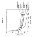
It is apparent from Fig. 2 that the sealing member made
of an alicyclic epoxy resin in each of Examples exhibits smaller
lowering of the intensity of emitted light than the epoxy resin
(Comparative Example 3) containing an aromatic compound. That
is, deterioration (yellowing) was so little that the sealing
member exhibits characteristic equal to the characteristic of
that made of glass even in the case where an acid anhydride
polymerization catalyst having a carbonyl group capable of
serving as an active seed is used (Examples 1 and 2). Moreover,
the degree of deterioration is further lightened when a cationic
polymerization catalyst having no active seed is used as a
polymerization catalyst (Example 3).
The present invention is not limited to the description
of the mode for carrying out the invention and the embodiment
thereof at all, and includes various modifications that can
be conceived easily by those skilled in the art without departing
the scope of claim.