EP1116864A2 - Heating an automotive catalyst - Google Patents
Heating an automotive catalyst Download PDFInfo
- Publication number
- EP1116864A2 EP1116864A2 EP01300102A EP01300102A EP1116864A2 EP 1116864 A2 EP1116864 A2 EP 1116864A2 EP 01300102 A EP01300102 A EP 01300102A EP 01300102 A EP01300102 A EP 01300102A EP 1116864 A2 EP1116864 A2 EP 1116864A2
- Authority
- EP
- European Patent Office
- Prior art keywords
- hydrogen
- oxygen
- catalyst
- temperature
- catalyst substrate
- Prior art date
- Legal status (The legal status is an assumption and is not a legal conclusion. Google has not performed a legal analysis and makes no representation as to the accuracy of the status listed.)
- Withdrawn
Links
Images


Classifications
-
- F—MECHANICAL ENGINEERING; LIGHTING; HEATING; WEAPONS; BLASTING
- F01—MACHINES OR ENGINES IN GENERAL; ENGINE PLANTS IN GENERAL; STEAM ENGINES
- F01N—GAS-FLOW SILENCERS OR EXHAUST APPARATUS FOR MACHINES OR ENGINES IN GENERAL; GAS-FLOW SILENCERS OR EXHAUST APPARATUS FOR INTERNAL-COMBUSTION ENGINES
- F01N3/00—Exhaust or silencing apparatus having means for purifying, rendering innocuous, or otherwise treating exhaust
- F01N3/08—Exhaust or silencing apparatus having means for purifying, rendering innocuous, or otherwise treating exhaust for rendering innocuous
- F01N3/10—Exhaust or silencing apparatus having means for purifying, rendering innocuous, or otherwise treating exhaust for rendering innocuous by thermal or catalytic conversion of noxious components of exhaust
- F01N3/18—Exhaust or silencing apparatus having means for purifying, rendering innocuous, or otherwise treating exhaust for rendering innocuous by thermal or catalytic conversion of noxious components of exhaust characterised by methods of operation; Control
- F01N3/20—Exhaust or silencing apparatus having means for purifying, rendering innocuous, or otherwise treating exhaust for rendering innocuous by thermal or catalytic conversion of noxious components of exhaust characterised by methods of operation; Control specially adapted for catalytic conversion
- F01N3/2006—Periodically heating or cooling catalytic reactors, e.g. at cold starting or overheating
-
- B—PERFORMING OPERATIONS; TRANSPORTING
- B01—PHYSICAL OR CHEMICAL PROCESSES OR APPARATUS IN GENERAL
- B01D—SEPARATION
- B01D53/00—Separation of gases or vapours; Recovering vapours of volatile solvents from gases; Chemical or biological purification of waste gases, e.g. engine exhaust gases, smoke, fumes, flue gases, aerosols
- B01D53/34—Chemical or biological purification of waste gases
- B01D53/74—General processes for purification of waste gases; Apparatus or devices specially adapted therefor
- B01D53/86—Catalytic processes
- B01D53/90—Injecting reactants
-
- B—PERFORMING OPERATIONS; TRANSPORTING
- B01—PHYSICAL OR CHEMICAL PROCESSES OR APPARATUS IN GENERAL
- B01D—SEPARATION
- B01D53/00—Separation of gases or vapours; Recovering vapours of volatile solvents from gases; Chemical or biological purification of waste gases, e.g. engine exhaust gases, smoke, fumes, flue gases, aerosols
- B01D53/34—Chemical or biological purification of waste gases
- B01D53/92—Chemical or biological purification of waste gases of engine exhaust gases
- B01D53/94—Chemical or biological purification of waste gases of engine exhaust gases by catalytic processes
- B01D53/9495—Controlling the catalytic process
-
- B—PERFORMING OPERATIONS; TRANSPORTING
- B01—PHYSICAL OR CHEMICAL PROCESSES OR APPARATUS IN GENERAL
- B01D—SEPARATION
- B01D2251/00—Reactants
- B01D2251/10—Oxidants
- B01D2251/102—Oxygen
-
- B—PERFORMING OPERATIONS; TRANSPORTING
- B01—PHYSICAL OR CHEMICAL PROCESSES OR APPARATUS IN GENERAL
- B01D—SEPARATION
- B01D2251/00—Reactants
- B01D2251/20—Reductants
- B01D2251/202—Hydrogen
-
- B—PERFORMING OPERATIONS; TRANSPORTING
- B01—PHYSICAL OR CHEMICAL PROCESSES OR APPARATUS IN GENERAL
- B01D—SEPARATION
- B01D2258/00—Sources of waste gases
- B01D2258/01—Engine exhaust gases
- B01D2258/012—Diesel engines and lean burn gasoline engines
-
- F—MECHANICAL ENGINEERING; LIGHTING; HEATING; WEAPONS; BLASTING
- F01—MACHINES OR ENGINES IN GENERAL; ENGINE PLANTS IN GENERAL; STEAM ENGINES
- F01N—GAS-FLOW SILENCERS OR EXHAUST APPARATUS FOR MACHINES OR ENGINES IN GENERAL; GAS-FLOW SILENCERS OR EXHAUST APPARATUS FOR INTERNAL-COMBUSTION ENGINES
- F01N2610/00—Adding substances to exhaust gases
- F01N2610/04—Adding substances to exhaust gases the substance being hydrogen
-
- F—MECHANICAL ENGINEERING; LIGHTING; HEATING; WEAPONS; BLASTING
- F01—MACHINES OR ENGINES IN GENERAL; ENGINE PLANTS IN GENERAL; STEAM ENGINES
- F01N—GAS-FLOW SILENCERS OR EXHAUST APPARATUS FOR MACHINES OR ENGINES IN GENERAL; GAS-FLOW SILENCERS OR EXHAUST APPARATUS FOR INTERNAL-COMBUSTION ENGINES
- F01N3/00—Exhaust or silencing apparatus having means for purifying, rendering innocuous, or otherwise treating exhaust
- F01N3/08—Exhaust or silencing apparatus having means for purifying, rendering innocuous, or otherwise treating exhaust for rendering innocuous
- F01N3/10—Exhaust or silencing apparatus having means for purifying, rendering innocuous, or otherwise treating exhaust for rendering innocuous by thermal or catalytic conversion of noxious components of exhaust
- F01N3/18—Exhaust or silencing apparatus having means for purifying, rendering innocuous, or otherwise treating exhaust for rendering innocuous by thermal or catalytic conversion of noxious components of exhaust characterised by methods of operation; Control
- F01N3/20—Exhaust or silencing apparatus having means for purifying, rendering innocuous, or otherwise treating exhaust for rendering innocuous by thermal or catalytic conversion of noxious components of exhaust characterised by methods of operation; Control specially adapted for catalytic conversion
- F01N3/206—Adding periodically or continuously substances to exhaust gases for promoting purification, e.g. catalytic material in liquid form, NOx reducing agents
-
- Y—GENERAL TAGGING OF NEW TECHNOLOGICAL DEVELOPMENTS; GENERAL TAGGING OF CROSS-SECTIONAL TECHNOLOGIES SPANNING OVER SEVERAL SECTIONS OF THE IPC; TECHNICAL SUBJECTS COVERED BY FORMER USPC CROSS-REFERENCE ART COLLECTIONS [XRACs] AND DIGESTS
- Y02—TECHNOLOGIES OR APPLICATIONS FOR MITIGATION OR ADAPTATION AGAINST CLIMATE CHANGE
- Y02A—TECHNOLOGIES FOR ADAPTATION TO CLIMATE CHANGE
- Y02A50/00—TECHNOLOGIES FOR ADAPTATION TO CLIMATE CHANGE in human health protection, e.g. against extreme weather
- Y02A50/20—Air quality improvement or preservation, e.g. vehicle emission control or emission reduction by using catalytic converters
-
- Y—GENERAL TAGGING OF NEW TECHNOLOGICAL DEVELOPMENTS; GENERAL TAGGING OF CROSS-SECTIONAL TECHNOLOGIES SPANNING OVER SEVERAL SECTIONS OF THE IPC; TECHNICAL SUBJECTS COVERED BY FORMER USPC CROSS-REFERENCE ART COLLECTIONS [XRACs] AND DIGESTS
- Y02—TECHNOLOGIES OR APPLICATIONS FOR MITIGATION OR ADAPTATION AGAINST CLIMATE CHANGE
- Y02T—CLIMATE CHANGE MITIGATION TECHNOLOGIES RELATED TO TRANSPORTATION
- Y02T10/00—Road transport of goods or passengers
- Y02T10/10—Internal combustion engine [ICE] based vehicles
- Y02T10/12—Improving ICE efficiencies
Definitions
- This invention relates generally to the field of automotive catalysts for the oxidation or reduction of emissions from a fossil fuelled internal combustion engine, and more particularly to technology for heating such catalyst by spontaneous combustion of hydrogen when exposed to the catalyst independent of any emissions.
- a group of recently issued and related patents disclose a method and apparatus to achieve heating of the catalyst by introducing a mixture of air and hydrogen to either the combustion chamber of the engine or to the air existing in the exhaust pipe upstream of a catalytic converter.
- the mixture is intended to combust within the engine to carry heat to the catalyst or spontaneously and exothermically combust when it is exposed to the catalyst.
- Hydrogen is supplied from a storage tank that is regularly filled with hydrogen produced on board the automotive vehicle by an electrolysis system. On-board electrolysis systems are readily known in the art as evidenced by the discussions in the above referenced patents.
- the systems essentially use electrical energy, derived from the vehicle's storage battery or generator, to disassociate water into its constituents, one of which is hydrogen. Care is taken to filter and purify the hydrogen to be free of any oxygen and other contaminants by reforming water with the constituent oxygen.
- the main body of electrolysis oxygen that is not contaminating the hydrogen is vented to atmosphere. Hydrogen is delivered to the air mixture for spontaneous combustion at a pressure of about 30-45 psig, is dispersed at flow rates of 80-200 litres per minute so that it constitutes 1-28% of the mixture.
- the invention is a method of conditioning an automotive catalyst of the type that induces reactive catalysis of HC and CO introduced to such catalyst as engine exhaust gas from an automotive engine of a vehicle.
- the method comprises the steps of: (a) electrolysing water on-board said vehicle to derive and store separate proportions of hydrogen and oxygen at pressures in the range of 50-100 psi, (b) immediately upon initiation of engine starting, rapidly transferring stoichiometric proportions of the separated and stored hydrogen and oxygen to a front face location of a catalyst substrate to heat the catalyst substrate by spontaneous catalytic recombination of the hydrogen and oxygen and thereby more efficiently raise the temperature of the catalyst substrate rapidly to a temperature at which certain emissions can be catalytically converted, (c) complete cranking of the engine to admit emissions laden with CO and HC to the catalyst substrate while continuing to transfer stoichiometric proportions of the hydrogen and oxygen to the front face location for raising the substrate temperature to about 300°C, and (d) ceasing introduction of the hydrogen
- the invention in a second aspect, provides an apparatus for heating an automotive catalyst to a catalytically reactive condition for automotive emissions, comprising (a) an on-board electrolysis system for producing and separately storing quantities of relatively pure hydrogen and oxygen in stoichiometric proportions and at generally equal pressures, (b) a frontal catalyst face defining entrances to multi-channelled catalyst laden flow paths , and (c) a controllable transfer line for selectively communicating hydrogen and a controllable transfer line for selectively communicating oxygen, the communications being to the front face whereby efficient spontaneous exothermic recombination of the hydrogen and oxygen may take place immediately upon being transferred to such location regardless of ambient temperatures.
- a method and apparatus embodying the invention overcome the inefficiencies of the prior art by (i) utilising essentially the exact stoichiometric proportions of hydrogen and oxygen produced by the on-board electrolysis system and avoid any use of air that can contribute as a source of oxygen for the spontaneous catalysed combustion, and (ii) prevent creation of the mixture until it can be introduced at the immediate face of the precious metal laden automotive catalyst.
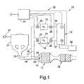
- an apparatus 10 is carried on-board a vehicle 9 and is used to very rapidly preheat an automotive close-coupled light-off catalyst 11 to an effective emission conversion temperature from a cold start or ambient temperature condition.
- the apparatus broadly comprises an electrolysis system 12 for generating hydrogen and oxygen, a frontal catalyst face 15, gas transfer lines 16 and 17 leading from the electrolysis system to the frontal catalyst face 15, storage tanks 13, 14 residing respectively in such transfer lines, and valves18 for selectively controlling gas flow through the transfer lines to or from the storage tanks.
- Catalyst 11 is carried on the vehicle 9 and is supported in exhaust pipe 19 in a position relatively close to manifold 20 of a fossil-fuelled internal combustion engine 21.
- Apparatus 10 causes catalyst 11 to quickly reach 50% conversion efficiency for THC and NO x emissions in about 1/3 the time it would normally take for state-of-the-art devices to do so and at less cost.
- Other on-board catalysts, such as underbody catalyst 22 are made more efficient by the enhanced rapid heating action of light-off catalyst 11.
- Separate on-board pressurised supplies of relatively pure oxygen and hydrogen in respective tanks 14 and 13 are used to introduce stoichiometric proportions of such gases to the frontal catalyst face 15 (stoichiometric meaning about a 2:1 ratio of H 2 /O 2 ) stoichiometric proportions are created by adapting and sizing the nozzles 23,24 to admit the desired volumetric ratio of hydrogen and oxygen gas.
- Use and replenishment of the stored gas supplies is controlled by valves 18.
- Transfer line 16 has electrically actuated solenoid vales 25,26 on opposite sides of tank 13 to selectively draw and/or admit hydrogen to tank 13;
- transfer line 17 has electrically actuated solenoid valves 27,28 to selectively draw and/or admit oxygen to tank 14.
- the respective gases are stored at generally equal pressures in the range of 60-1000 psi.
- the valves 18 When the valves 18 are operated to draw hydrogen and oxygen, the gases will flow through their respective lines and through adjacent nozzles 23,24 to produce short diverging and overlapping spray patterns 29,30 that induce immediate gas intermixing of hydrogen and oxygen on the frontal catalyst face 15.
- This type of mixing allows for some discontinuous sites of hydrogen and oxygen to exist on the face so as to more effectively react with emissions, when they begin to flow, to lower the cold-start conversion temperature for the respective constituents of the emissions and thereby shortening the time to heat up.
- apparatus 10 is operated in a sequence of steps to achieve the extremely rapid heat-up effect.
- timed circuits 32 regulated by controller 31
- This condition continues for about a one second interval during which time the blown oxygen and hydrogen react with each other in the presence of the catalyst material to exothermically recombine and produce water.
- the catalyst material is preferably a precious metal such as palladium o platinum.
- the hydrogen and oxygen now meet with some of such emissions at face 15 during which time continued reaction of hydrogen and oxygen occurs to raise the temperature to about 180°C.
- the electrolysis cell is powered by the timed circuits connections 32 and valves 26,28 are opened allowing for the admission of newly generated hydrogen and oxygen to the storage tanks, The pressure in tanks 13,14 remains in the range of 30-60 psi even though continued withdrawal takes place.
- the temperature of at least the face is surprisingly able to begin inducing oxidation of HC (when in the presence of the catalyst) at a temperature as low as 210°C, this is lower than that observable by the prior art (see Figure 3 for comparison).
- Exothermic oxidation of HC and CO, along with some further reformation of water, increases the catalyst temperature further; over another period of about 7 seconds, 300°C will be attained accompanied by a catalyst conversion efficiency of at least 50%.
- the attainment of 50% efficiency at 300°C within 10 seconds not only meets federally mandated ULEV standards but does so in one third of the time required by such standards.
- the tanks 13,14 are now ready to supply the necessary gases to achieve a preheating effect should the engine need to be restarted.
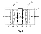
- Figure 4 illustrates one form of an on-board electrolytic cell 35; the cell has a cathode 36 and anode 37 placed adjacent a solid phase polymer electrolyte 38.
- the cell is filled with de-ionised water from a reservoir 39 (the water having a quality similar to that used for filling battery cells) to keep the electrolyte and electrodes wet.
- An ion exchange membrane 40 (coated with Pt precious metal on opposite sides) separates the cathode and anode.
- the membrane 40 is supplied with electrical power, from a source connected to controller 31 or a battery, to induce circulation of the electrolyte and hydrogen there through.
- Elements 42,43 separate the generated oxygen and hydrogen.
Landscapes
- Engineering & Computer Science (AREA)
- Chemical & Material Sciences (AREA)
- Chemical Kinetics & Catalysis (AREA)
- Environmental & Geological Engineering (AREA)
- Health & Medical Sciences (AREA)
- Combustion & Propulsion (AREA)
- General Chemical & Material Sciences (AREA)
- Oil, Petroleum & Natural Gas (AREA)
- Analytical Chemistry (AREA)
- Biomedical Technology (AREA)
- Toxicology (AREA)
- Mechanical Engineering (AREA)
- General Engineering & Computer Science (AREA)
- Exhaust Gas After Treatment (AREA)
- Output Control And Ontrol Of Special Type Engine (AREA)
- Exhaust Gas Treatment By Means Of Catalyst (AREA)
- Catalysts (AREA)
Abstract
Description
- This invention relates generally to the field of automotive catalysts for the oxidation or reduction of emissions from a fossil fuelled internal combustion engine, and more particularly to technology for heating such catalyst by spontaneous combustion of hydrogen when exposed to the catalyst independent of any emissions.
- A group of recently issued and related patents (US Patents 5,813,222; 5,953,908; 5,964,089; 5,845,485; and 5,964,089) disclose a method and apparatus to achieve heating of the catalyst by introducing a mixture of air and hydrogen to either the combustion chamber of the engine or to the air existing in the exhaust pipe upstream of a catalytic converter. The mixture is intended to combust within the engine to carry heat to the catalyst or spontaneously and exothermically combust when it is exposed to the catalyst. Hydrogen is supplied from a storage tank that is regularly filled with hydrogen produced on board the automotive vehicle by an electrolysis system. On-board electrolysis systems are readily known in the art as evidenced by the discussions in the above referenced patents. The systems essentially use electrical energy, derived from the vehicle's storage battery or generator, to disassociate water into its constituents, one of which is hydrogen. Care is taken to filter and purify the hydrogen to be free of any oxygen and other contaminants by reforming water with the constituent oxygen. The main body of electrolysis oxygen that is not contaminating the hydrogen is vented to atmosphere. Hydrogen is delivered to the air mixture for spontaneous combustion at a pressure of about 30-45 psig, is dispersed at flow rates of 80-200 litres per minute so that it constitutes 1-28% of the mixture. Due to the inefficiency of adding hydrogen to air at a location well upstream of the catalyst, the patents suggest adding a small electrical heater in instances where the ambient temperature conditions can be as low as -7°C (see '222 patent at column 9, lines 28-35). Such a proposal points out the shortcomings of the state of the art. Such patents also taking the electrolysis oxygen and adding it to the air flow when creating the combustible mixture, as the patents suggest. Unfortunately this does little to change the inefficiency of the approach..
- In a first aspect, the invention is a method of conditioning an automotive catalyst of the type that induces reactive catalysis of HC and CO introduced to such catalyst as engine exhaust gas from an automotive engine of a vehicle. The method comprises the steps of: (a) electrolysing water on-board said vehicle to derive and store separate proportions of hydrogen and oxygen at pressures in the range of 50-100 psi, (b) immediately upon initiation of engine starting, rapidly transferring stoichiometric proportions of the separated and stored hydrogen and oxygen to a front face location of a catalyst substrate to heat the catalyst substrate by spontaneous catalytic recombination of the hydrogen and oxygen and thereby more efficiently raise the temperature of the catalyst substrate rapidly to a temperature at which certain emissions can be catalytically converted, (c) complete cranking of the engine to admit emissions laden with CO and HC to the catalyst substrate while continuing to transfer stoichiometric proportions of the hydrogen and oxygen to the front face location for raising the substrate temperature to about 300°C, and (d) ceasing introduction of the hydrogen and oxygen when the catalyst substrate has reached full operational temperature for optimum emission conversion.
- The invention, in a second aspect, provides an apparatus for heating an automotive catalyst to a catalytically reactive condition for automotive emissions, comprising (a) an on-board electrolysis system for producing and separately storing quantities of relatively pure hydrogen and oxygen in stoichiometric proportions and at generally equal pressures, (b) a frontal catalyst face defining entrances to multi-channelled catalyst laden flow paths , and (c) a controllable transfer line for selectively communicating hydrogen and a controllable transfer line for selectively communicating oxygen, the communications being to the front face whereby efficient spontaneous exothermic recombination of the hydrogen and oxygen may take place immediately upon being transferred to such location regardless of ambient temperatures.
- A method and apparatus embodying the invention overcome the inefficiencies of the prior art by (i) utilising essentially the exact stoichiometric proportions of hydrogen and oxygen produced by the on-board electrolysis system and avoid any use of air that can contribute as a source of oxygen for the spontaneous catalysed combustion, and (ii) prevent creation of the mixture until it can be introduced at the immediate face of the precious metal laden automotive catalyst.
- The invention will now be described further, by way of example, with reference to the accompanying drawings, in which:
- Figure 1 is a schematic layout of an on-board vehicular apparatus embodying this invention for rapidly heating a catalyst from cold-start;
- Figure 2 is a flow diagram of sequential timed steps performed by the apparatus;
- Figure 3 is a graphical illustration comparing light-off temperatures for catalytic conversion of HC and CO with and without the use of the H2 and O2 combination of this invention; and
- Figure 4 is a general illustration of one type of electrolytic system that may be used on-board an automotive vehicle which facilitates carrying out this invention.
-
- As shown in Figure 1, an
apparatus 10 is carried on-board a vehicle 9 and is used to very rapidly preheat an automotive close-coupled light-offcatalyst 11 to an effective emission conversion temperature from a cold start or ambient temperature condition. The apparatus broadly comprises anelectrolysis system 12 for generating hydrogen and oxygen, afrontal catalyst face 15,gas transfer lines frontal catalyst face 15,storage tanks - Catalyst 11 is carried on the vehicle 9 and is supported in
exhaust pipe 19 in a position relatively close to manifold 20 of a fossil-fuelledinternal combustion engine 21.Apparatus 10 causescatalyst 11 to quickly reach 50% conversion efficiency for THC and NOx emissions in about 1/3 the time it would normally take for state-of-the-art devices to do so and at less cost. Other on-board catalysts, such asunderbody catalyst 22 are made more efficient by the enhanced rapid heating action of light-offcatalyst 11. - Separate on-board pressurised supplies of relatively pure oxygen and hydrogen in
respective tanks nozzles valves 18.Transfer line 16 has electrically actuatedsolenoid vales tank 13 to selectively draw and/or admit hydrogen to tank 13;transfer line 17 has electrically actuatedsolenoid valves valves 18 are operated to draw hydrogen and oxygen, the gases will flow through their respective lines and throughadjacent nozzles spray patterns 29,30 that induce immediate gas intermixing of hydrogen and oxygen on thefrontal catalyst face 15. This type of mixing allows for some discontinuous sites of hydrogen and oxygen to exist on the face so as to more effectively react with emissions, when they begin to flow, to lower the cold-start conversion temperature for the respective constituents of the emissions and thereby shortening the time to heat up. - No electrical energy is needed at the first instance of use of the stored hydrogen and oxygen. Energy for electrolysis is required sporadically only during times the engine is running and thus reduces energy and equipment requirements.
- As shown schematically in Figure 2,
apparatus 10 is operated in a sequence of steps to achieve the extremely rapid heat-up effect. At step (1), time=0 seconds,ignition key 31 is turned to start theengine 21 and actuate timed circuits 32 (regulated by controller 31) to openvalves valves frontal catalyst face 15 while there is no engine emissions in theexhaust pipe 10 or incatalyst 11. This condition continues for about a one second interval during which time the blown oxygen and hydrogen react with each other in the presence of the catalyst material to exothermically recombine and produce water. This releases heat to the catalyst at an effective rate equivalent to a 400 watt heater; such heating rapidly increases the temperature of at least the frontal catalyst face from ambient to about 125-150°C. The catalyst material is preferably a precious metal such as palladium o platinum. - At step (2), time = 1 second, the
engine 21 cranks rotation of the pistons for about one second which begins to produce someengine exhaust 33 comprised of CO and HC; such exhaust flows into the exhaust pipe at a rate of typically five litres per second. The hydrogen and oxygen now meet with some of such emissions atface 15 during which time continued reaction of hydrogen and oxygen occurs to raise the temperature to about 180°C. With the engine now beginning to run, the electrolysis cell is powered by thetimed circuits connections 32 andvalves tanks - At step (3), time = 2 seconds, the temperature of at least the frontal catalyst face rises to a sufficient temperature of about 180°C to begin inducing oxidation of CO when in the presence of hydrogen and oxygen; the temperature will now rise during the next one second to about 210°C due primarily to CO oxidation and secondarily to water reformation. Without the use of this invention, CO oxidation would begin at about 221°C (see Figure 3).
- At step (4), time = 3 seconds, the temperature of at least the face is surprisingly able to begin inducing oxidation of HC (when in the presence of the catalyst) at a temperature as low as 210°C, this is lower than that observable by the prior art (see Figure 3 for comparison). Exothermic oxidation of HC and CO, along with some further reformation of water, increases the catalyst temperature further; over another period of about 7 seconds, 300°C will be attained accompanied by a catalyst conversion efficiency of at least 50%. The attainment of 50% efficiency at 300°C within 10 seconds not only meets federally mandated ULEV standards but does so in one third of the time required by such standards. Part of the reason for such rapid increase in temperature, while using such low flow rates of hydrogen and oxygen, is the placement of initial gas mixing at the face of the catalyst; this permits some discontinuous sites of hydrogen relative to CO to induce lower light-off temperatures for the CO and HC. Further admission of hydrogen and oxygen is continued for another 5 seconds to additionally raise the temperature of the catalyst.
- At step (5), time = 15 seconds, the
entire catalyst 11 should be fully warm and be at a temperature of about 350°C. Valves 25,27 are automatically closed whilevalves tanks - At step (6), time = 30 seconds,
valves timed circuits 32 and the electrolysis cell is depowered (turned off). Thetanks - Figure 4 illustrates one form of an on-board
electrolytic cell 35; the cell has acathode 36 andanode 37 placed adjacent a solidphase polymer electrolyte 38. The cell is filled with de-ionised water from a reservoir 39 (the water having a quality similar to that used for filling battery cells) to keep the electrolyte and electrodes wet. An ion exchange membrane 40 (coated with Pt precious metal on opposite sides) separates the cathode and anode. Themembrane 40 is supplied with electrical power, from a source connected tocontroller 31 or a battery, to induce circulation of the electrolyte and hydrogen there through.Elements anode 37, water is disassociated into hydrogen and oxygen ions accompanied by release of electrons to the anode. Hydrogen ions migrate through the membrane to collect at thecathode 36 where they evolve in hydrogen molecules by addition of electrons from the cathode. Generated oxygen particles collect about the anode and form oxygen gas with sufficient pressure to flow to thestorage tank 14 viatransfer line 17. Generated hydrogen gas collects along the cathode and does so with sufficient pressure to flow to tank 13 viatransfer line 16.
Claims (11)
- A method of conditioning an automotive catalyst (11) of the type that induces reactive catalysis of HC and CO introduced to such catalyst as engine exhaust gas from an engine of a vehicle, the method comprising:(a) electrolysing water on-board said vehicle to derive and store separate proportions of hydrogen and oxygen at pressures in the range of 50-100 psi;(b) immediately upon initiation of engine starting, rapidly transferring stoichiometric proportions of the separated and stored hydrogen and oxygen to a front face location of a catalyst substrate to heat the catalyst substrate by spontaneous catalytic recombination of the hydrogen and oxygen and thereby raise the temperature of the catalyst substrate rapidly to a temperature at which certain emissions can be catalytically converted;(c) complete cranking of the engine to admit emissions laden with CO and HC to the catalyst substrate while continuing to transfer stoichiometric proportions of the hydrogen and oxygen to said front face location for raising the substrate temperature to about 300°C; and(d) ceasing introduction of the hydrogen and oxygen when the catalyst substrate has reached a full operational temperature for optimum emission conversion..
- A method as claimed in claim 1, in which during step (b), no emissions are present at or in said catalyst substrate and the electrolysing is not operational.
- A method as claimed in claim 1, in which during step (c), the spontaneous recombination of hydrogen and oxygen first raises at least said front face to a temperature of 180°C for inducing the start of oxidation of CO, and thence to a temperature of 210°C for inducing the start of HC oxidation in said catalyst substrate.
- A method as claimed in claim 1, in which step (b) has a time period of about 1-1.5 seconds from the initiation of engine starting.
- A method as claimed in claim 1, in which step (c) has a time period that ends about 15 seconds from the initiation of engine starting.
- A method as claimed in claim 1, in which during step (c), electrolysing is electrically energised and electrolysing is de-energised after about 15 seconds after completion of step (d).
- Apparatus for heating an automotive catalyst (11) to a catalytically reactive condition for automotive emissions, comprising:(a) an on-board electrolysis system (12) for producing and separately storing quantities of relatively pure hydrogen and oxygen in stoichiometric proportions and at generally equal pressures;(b) a frontal catalyst face (15) defining entrances to multi-channelled catalyst laden flow paths;(c) a controllable transfer line for selectively communicating hydrogen (16) and a controllable transfer line (17) for selectively communicating oxygen, the communications being to the front face whereby efficient spontaneous exothermic recombination of the hydrogen and oxygen takes place immediately upon being transferred to such location regardless of ambient temperatures.
- An apparatus as claimed in claim 7, in which each of said transfer lines have a nozzle adapted and sized to deliver stoichiometric proportions of the respective hydrogen and oxygen to said front face.
- An apparatus as claimed in claim 8, in which said nozzles deliver diverging and overlapping sprays of said hydrogen and oxygen which allows some discontinuous sites of hydrogen and emission gases that promote lower temperature light-off of the emissions.
- An apparatus as claimed in claim 7, in which said hydrogen and oxygen are stored at generally equal pressures in the range of 50-100 psi.
- An apparatus as claimed in claim 7, in which the front face is loaded with a catalyst in the density range of 100 to 300 g/ft3.
Applications Claiming Priority (2)
| Application Number | Priority Date | Filing Date | Title |
|---|---|---|---|
| US09/482,299 US6272849B1 (en) | 2000-01-13 | 2000-01-13 | Apparatus and method for heating an automotive catalyst to an emission reactive condition |
| US482299 | 2000-01-13 |
Publications (2)
| Publication Number | Publication Date |
|---|---|
| EP1116864A2 true EP1116864A2 (en) | 2001-07-18 |
| EP1116864A3 EP1116864A3 (en) | 2004-01-28 |
Family
ID=23915518
Family Applications (1)
| Application Number | Title | Priority Date | Filing Date |
|---|---|---|---|
| EP01300102A Withdrawn EP1116864A3 (en) | 2000-01-13 | 2001-01-08 | Heating an automotive catalyst |
Country Status (3)
| Country | Link |
|---|---|
| US (1) | US6272849B1 (en) |
| EP (1) | EP1116864A3 (en) |
| JP (1) | JP2001227327A (en) |
Cited By (1)
| Publication number | Priority date | Publication date | Assignee | Title |
|---|---|---|---|---|
| CN102278177A (en) * | 2011-04-27 | 2011-12-14 | 汪家琳 | Device and method for efficiently utilizing tail gas of combustion engine |
Families Citing this family (14)
| Publication number | Priority date | Publication date | Assignee | Title |
|---|---|---|---|---|
| US6729125B2 (en) * | 2000-09-19 | 2004-05-04 | Nissan Motor Co., Ltd. | Exhaust gas purifying system |
| US20040098969A1 (en) * | 2002-11-21 | 2004-05-27 | Maxim Lyubovsky | Method for reducing the lightoff temperature of a catalyst |
| US6981367B2 (en) * | 2003-06-25 | 2006-01-03 | General Motors Corporation | Hydrogen and oxygen generation from a water vapor containing exhaust |
| US20040265201A1 (en) * | 2003-06-25 | 2004-12-30 | Norman Dale Brinkman | NOx removal system |
| US7178339B2 (en) * | 2004-04-07 | 2007-02-20 | Lockheed Martin Corporation | Closed-loop cooling system for a hydrogen/oxygen based combustor |
| JP2009079540A (en) * | 2007-09-26 | 2009-04-16 | Mitsubishi Heavy Ind Ltd | Exhaust gas purification system and exhaust gas purification method |
| US20090260350A1 (en) * | 2008-04-18 | 2009-10-22 | Leslie Bromberg | Enhanced aftertreatment apparatus regeneration using spatially controlled hydrogen-rich gas |
| US8230826B2 (en) * | 2010-04-08 | 2012-07-31 | Ford Global Technologies, Llc | Selectively storing reformate |
| DE102010040016A1 (en) | 2010-08-31 | 2012-03-01 | Bayerische Motoren Werke Aktiengesellschaft | Method for heating product in fluid line, particularly catalytic converter located in exhaust pipe of internal combustion engine, involves loading adsorbent with liquid when temperature of catalyst housing stays below predetermined value |
| MX348820B (en) | 2011-12-30 | 2017-06-30 | Coca Cola Co | System and method for forming a metal beverage container using blow molding. |
| IL251356B (en) * | 2017-03-23 | 2018-11-29 | Dan Yitzhaki | An exhaust after treatment system for a diesel engine and gasoline engine for an improved cold start up and improved denox |
| JP6958464B2 (en) * | 2018-04-11 | 2021-11-02 | トヨタ自動車株式会社 | Exhaust purification device for internal combustion engine |
| JP2020118068A (en) * | 2019-01-22 | 2020-08-06 | 株式会社豊田中央研究所 | Early activation system for exhaust gas purification catalyst and early activation method for exhaust gas purification catalyst |
| CN110107380A (en) * | 2019-04-17 | 2019-08-09 | 湖南冠拓科技股份有限公司 | A kind of diesel engine vent gas carbon particle collector removes carbon method and apparatus |
Citations (3)
| Publication number | Priority date | Publication date | Assignee | Title |
|---|---|---|---|---|
| US5813222A (en) | 1994-10-07 | 1998-09-29 | Appleby; Anthony John | Method and apparatus for heating a catalytic converter to reduce emissions |
| US5845485A (en) | 1996-07-16 | 1998-12-08 | Lynntech, Inc. | Method and apparatus for injecting hydrogen into a catalytic converter |
| US5964089A (en) | 1997-06-27 | 1999-10-12 | Lynntech, Inc | Diagnostics and control of an on board hydrogen generation and delivery system |
Family Cites Families (11)
| Publication number | Priority date | Publication date | Assignee | Title |
|---|---|---|---|---|
| GB1372160A (en) * | 1972-03-22 | 1974-10-30 | Nissan Motor | Exhaust cleaning apparatus for internal combustion engines |
| US4368696A (en) * | 1980-07-29 | 1983-01-18 | Reinhardt Weldon E | Electrolytic supplemental fuel generation for motor vehicles |
| JP2921158B2 (en) * | 1991-04-17 | 1999-07-19 | トヨタ自動車株式会社 | Exhaust gas purification device for internal combustion engine |
| US5272871A (en) * | 1991-05-24 | 1993-12-28 | Kabushiki Kaisha Toyota Chuo Kenkyusho | Method and apparatus for reducing nitrogen oxides from internal combustion engine |
| JPH05106430A (en) * | 1991-10-16 | 1993-04-27 | Toyota Central Res & Dev Lab Inc | Nitrogen oxide reduction device for internal combustion engine |
| DE4208609C2 (en) * | 1992-03-18 | 1994-12-15 | Daimler Benz Ag | Method for reducing the period of time until the operating temperature of an exhaust gas cleaning device arranged in the exhaust system of an internal combustion engine is reached |
| JP3391587B2 (en) * | 1994-11-18 | 2003-03-31 | 株式会社小松製作所 | Exhaust denitration equipment for diesel engines |
| US5685145A (en) * | 1995-02-07 | 1997-11-11 | Engelhard Corporation | Method and apparatus for performance enhancement of the manifold catalyst in the automotive exhaust system |
| JPH0932540A (en) * | 1995-07-13 | 1997-02-04 | Hino Motors Ltd | Exhaust emission control device of diesel engine |
| US5921076A (en) * | 1996-01-09 | 1999-07-13 | Daimler-Benz Ag | Process and apparatus for reducing nitrogen oxides in engine emissions |
| US6122909A (en) * | 1998-09-29 | 2000-09-26 | Lynntech, Inc. | Catalytic reduction of emissions from internal combustion engines |
-
2000
- 2000-01-13 US US09/482,299 patent/US6272849B1/en not_active Expired - Fee Related
-
2001
- 2001-01-08 EP EP01300102A patent/EP1116864A3/en not_active Withdrawn
- 2001-01-11 JP JP2001003407A patent/JP2001227327A/en active Pending
Patent Citations (4)
| Publication number | Priority date | Publication date | Assignee | Title |
|---|---|---|---|---|
| US5813222A (en) | 1994-10-07 | 1998-09-29 | Appleby; Anthony John | Method and apparatus for heating a catalytic converter to reduce emissions |
| US5953908A (en) | 1994-10-07 | 1999-09-21 | Appleby; Anthony John | Method and apparatus for heating a catalytic converter to reduce emissions |
| US5845485A (en) | 1996-07-16 | 1998-12-08 | Lynntech, Inc. | Method and apparatus for injecting hydrogen into a catalytic converter |
| US5964089A (en) | 1997-06-27 | 1999-10-12 | Lynntech, Inc | Diagnostics and control of an on board hydrogen generation and delivery system |
Cited By (2)
| Publication number | Priority date | Publication date | Assignee | Title |
|---|---|---|---|---|
| CN102278177A (en) * | 2011-04-27 | 2011-12-14 | 汪家琳 | Device and method for efficiently utilizing tail gas of combustion engine |
| CN102278177B (en) * | 2011-04-27 | 2014-05-07 | 汪家琳 | Device and method for efficiently utilizing tail gas of combustion engine |
Also Published As
| Publication number | Publication date |
|---|---|
| US6272849B1 (en) | 2001-08-14 |
| JP2001227327A (en) | 2001-08-24 |
| EP1116864A3 (en) | 2004-01-28 |
Similar Documents
| Publication | Publication Date | Title |
|---|---|---|
| US6272849B1 (en) | Apparatus and method for heating an automotive catalyst to an emission reactive condition | |
| EP0784741B1 (en) | Method and apparatus for heating a catalytic converter to reduce emissions | |
| EP1184545A2 (en) | Method and apparatus for injecting hydrogen into a catalytic converter | |
| US6235254B1 (en) | Hybrid catalyst heating system with water removal for enhanced emissions control | |
| USRE39720E1 (en) | Catalytic reduction of emissions from internal combustion engines | |
| US6383468B1 (en) | Method for operating a system for water-vapor reforming of a hydrocarbon | |
| US4573435A (en) | Apparatus and method for generating hydrogen gas for use as a fuel additive in diesel engines | |
| US20090035192A1 (en) | Catalytic EGR oxidizer for IC engines and gas turbines | |
| WO2006021852A1 (en) | Integrated fuel injection system for on-board fuel reformer | |
| JPH07315802A (en) | Reforming reactor | |
| CA2946677C (en) | Method for exhaust gas aftertreatment and combustion system | |
| US20050132650A1 (en) | Fast light-off catalytic reformer | |
| JP2001296017A (en) | Combustion heating device, fuel reforming device including the same, and fuel cell system | |
| CN101636866A (en) | Fuel cell system running on liquefied petroleum gas | |
| CN1989068A (en) | Method and equipment of fuel reforming | |
| CN101457715A (en) | Mobile hydrogen making engine fuel system and device thereof | |
| US20040101722A1 (en) | Fuel cell system with heat exchanger for heating a reformer and vehicle containing same | |
| JP3711577B2 (en) | Fuel reformer | |
| JP2003335503A (en) | Hydrogen generator | |
| CN105347300A (en) | Methanol to hydrogen machine system with rapid cold boot | |
| JPH07126001A (en) | Fuel reformer | |
| JP2004189585A (en) | Hydrogen gas generator | |
| JP2004225894A (en) | Apparatus and method for heating hydrogen storage container | |
| CN207683373U (en) | Ethanol reformation fuel cell car | |
| KR102397622B1 (en) | An apparatus and a method for purifying exhaust gas from internal combustion engine |
Legal Events
| Date | Code | Title | Description |
|---|---|---|---|
| PUAI | Public reference made under article 153(3) epc to a published international application that has entered the european phase |
Free format text: ORIGINAL CODE: 0009012 |
|
| AK | Designated contracting states |
Kind code of ref document: A2 Designated state(s): AT BE CH CY DE DK ES FI FR GB GR IE IT LI LU MC NL PT SE TR |
|
| AX | Request for extension of the european patent |
Free format text: AL;LT;LV;MK;RO;SI |
|
| PUAL | Search report despatched |
Free format text: ORIGINAL CODE: 0009013 |
|
| AK | Designated contracting states |
Kind code of ref document: A3 Designated state(s): AT BE CH CY DE DK ES FI FR GB GR IE IT LI LU MC NL PT SE TR |
|
| AX | Request for extension of the european patent |
Extension state: AL LT LV MK RO SI |
|
| RIC1 | Information provided on ipc code assigned before grant |
Ipc: 7B 01D 53/90 B Ipc: 7F 01N 3/20 A |
|
| AKX | Designation fees paid |
Designated state(s): DE GB SE |
|
| STAA | Information on the status of an ep patent application or granted ep patent |
Free format text: STATUS: THE APPLICATION IS DEEMED TO BE WITHDRAWN |
|
| 18D | Application deemed to be withdrawn |
Effective date: 20040729 |