EP1116615A2 - Kühlsystem für ein Kraftfahrzeug - Google Patents
Kühlsystem für ein Kraftfahrzeug Download PDFInfo
- Publication number
- EP1116615A2 EP1116615A2 EP00122046A EP00122046A EP1116615A2 EP 1116615 A2 EP1116615 A2 EP 1116615A2 EP 00122046 A EP00122046 A EP 00122046A EP 00122046 A EP00122046 A EP 00122046A EP 1116615 A2 EP1116615 A2 EP 1116615A2
- Authority
- EP
- European Patent Office
- Prior art keywords
- coolant circuit
- circuit
- pump
- line
- coolant
- Prior art date
- Legal status (The legal status is an assumption and is not a legal conclusion. Google has not performed a legal analysis and makes no representation as to the accuracy of the status listed.)
- Withdrawn
Links
Images
Classifications
-
- B—PERFORMING OPERATIONS; TRANSPORTING
- B60—VEHICLES IN GENERAL
- B60H—ARRANGEMENTS OF HEATING, COOLING, VENTILATING OR OTHER AIR-TREATING DEVICES SPECIALLY ADAPTED FOR PASSENGER OR GOODS SPACES OF VEHICLES
- B60H1/00—Heating, cooling or ventilating devices
- B60H1/02—Heating, cooling or ventilating devices the heat being derived from the propulsion plant
- B60H1/04—Heating, cooling or ventilating devices the heat being derived from the propulsion plant from cooling liquid of the plant
- B60H1/08—Heating, cooling or ventilating devices the heat being derived from the propulsion plant from cooling liquid of the plant from other radiator than main radiator
-
- F—MECHANICAL ENGINEERING; LIGHTING; HEATING; WEAPONS; BLASTING
- F01—MACHINES OR ENGINES IN GENERAL; ENGINE PLANTS IN GENERAL; STEAM ENGINES
- F01P—COOLING OF MACHINES OR ENGINES IN GENERAL; COOLING OF INTERNAL-COMBUSTION ENGINES
- F01P5/00—Pumping cooling-air or liquid coolants
- F01P5/10—Pumping liquid coolant; Arrangements of coolant pumps
-
- F—MECHANICAL ENGINEERING; LIGHTING; HEATING; WEAPONS; BLASTING
- F01—MACHINES OR ENGINES IN GENERAL; ENGINE PLANTS IN GENERAL; STEAM ENGINES
- F01P—COOLING OF MACHINES OR ENGINES IN GENERAL; COOLING OF INTERNAL-COMBUSTION ENGINES
- F01P7/00—Controlling of coolant flow
- F01P7/14—Controlling of coolant flow the coolant being liquid
- F01P7/16—Controlling of coolant flow the coolant being liquid by thermostatic control
- F01P7/165—Controlling of coolant flow the coolant being liquid by thermostatic control characterised by systems with two or more loops
-
- F—MECHANICAL ENGINEERING; LIGHTING; HEATING; WEAPONS; BLASTING
- F01—MACHINES OR ENGINES IN GENERAL; ENGINE PLANTS IN GENERAL; STEAM ENGINES
- F01P—COOLING OF MACHINES OR ENGINES IN GENERAL; COOLING OF INTERNAL-COMBUSTION ENGINES
- F01P5/00—Pumping cooling-air or liquid coolants
- F01P5/10—Pumping liquid coolant; Arrangements of coolant pumps
- F01P2005/105—Using two or more pumps
-
- F—MECHANICAL ENGINEERING; LIGHTING; HEATING; WEAPONS; BLASTING
- F01—MACHINES OR ENGINES IN GENERAL; ENGINE PLANTS IN GENERAL; STEAM ENGINES
- F01P—COOLING OF MACHINES OR ENGINES IN GENERAL; COOLING OF INTERNAL-COMBUSTION ENGINES
- F01P2060/00—Cooling circuits using auxiliaries
- F01P2060/08—Cabin heater
Definitions
- the invention relates to a cooling system for a motor vehicle with a first Coolant circuit, which includes cooling channels of an internal combustion engine, and one second coolant circuit for vehicle interior heating, each circuit has at least one line, a pump and at least one heat exchanger and the second coolant circuit via an inlet point and an outlet point with the first coolant circuit is connected, the pump of the second cooling circuit is controllable.
- Such a cooling system is, for example, from FIG. 2 of DE-A1-3738412 known.
- the internal combustion engine has one first and a second coolant connection for a main coolant circuit, and a third and fourth coolant connection for a secondary coolant circuit, so that the engine can be cooled partially differently.
- Via an air flap 41 can Air heated inside the vehicle by the heat exchanger in the second coolant circuit are directed and there carry out a temperature control. Not required heated air is discharged to the outside. It is also common To control the arrangement on the water side, the heating capacity being higher than that Coolant quantity is controlled by means of a valve. However, the exact Control of low outputs places high demands on the valves used.
- the dependence of the heating power on coolant pressure also has a disadvantageous effect and - temperature from the current speed and load of the internal combustion engine out.
- valves to control the heating output for the Vehicle interior is a complex measure.
- the present invention is therefore based on the object of a remedy for to create problems described above.
- the second coolant circuit is particularly simple via a cross-coupling piece connected to the line of the first coolant circuit.
- the pump and the Heat exchanger of the second coolant circuit in a separate housing are arranged, which of course also have measuring and control elements can.
- the housing can also be a Have blowers.
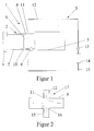
- the cooling system 1 shows a system diagram of the cooling system 1 according to the invention for a motor vehicle.
- the cooling system 1 has two cooling circuits 2, 3.
- the coolant circuit 2 contains a first heat exchanger 4, the main cooler, from which coolant is fed via a line 5 to the cooling channels (not shown) of the internal combustion engine 7 by means of a pump.
- the heated coolant is returned from the internal combustion engine 7 to the main cooler 4 via a line 8.
- a short-circuit line 9 branches off from line 8 to line 5, with the aid of a thermostat 10, in particular after a cold start, the operating temperature of the engine can be reached more quickly by bridging the main cooler 4.
- On the outflow side of the cooling ducts of the internal combustion engine 7 there is an inlet point 11 to the line 12 of the second coolant circuit 3.
- This second coolant circuit 3 also has a controllable pump 13 and a heat exchanger 14 arranged behind it, which serves to heat the passenger compartment of the vehicle.
- a line 15 connects the second coolant circuit 3 to the line 8 again via a drain point 16.
- the inlet point 11 and the outlet point 16 are connected to the line 8 in such a way that regardless of the liquid flow in the first coolant circuit 2, the liquid pressure of the inlet point 11 is equal to the liquid pressure of the outlet point 16. In this way, for example in summer operation, when no heating of the passenger compartment is desired, there is no coolant transport and therefore no motor waste heat transport through the second coolant circuit 3 as long as the pump 13 is not switched on.
- the pump 13 If the pump 13 is switched on, a simple change in the pump speed makes it possible to regulate the heat transport and thus to continuously regulate the passenger compartment temperature. In this way, the heat flow for heating the passenger compartment of the second coolant circuit 3 is also not influenced by fluctuations in the first coolant circuit 2 determined by the engine speed.
- Fig. 2 shows a possible cross-coupling piece 17 for coupling the second Coolant circuit 3 to the first coolant circuit 2. Furthermore, in this Figure the flow conditions with the pump 6 switched on and switched on Pump 13, i.e. heat transport to the passenger compartment, is shown.
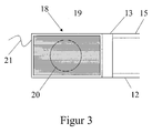
- FIG. 3 shows a housing 18 which is arranged freely in the passenger compartment 19.
- the housing 18 has, in addition to the electrically controllable pump 13, a controllable blower 20 with which the air flow rate can be influenced. Cooling water of the pump 13 is via the line 12 feedable, and discharged via line 15. Be on the electrical connection 21 the pump 13, the blower 20 and any existing measuring and control elements powered. Housing 18 may also be conventional Auxiliary heating can be combined without the engine block in the Parking heater mode is heated with. In a further embodiment, not shown branch from line 12 two lines connected in parallel, each with a housing 18, which subsequently flow back into line 15. This way it is possible partially to the passenger interior, for example the driver and / or passenger side heat. It should be clear that the lines 12, 15 are particularly simple Way can be designed as a double hose.
Landscapes
- Engineering & Computer Science (AREA)
- Chemical & Material Sciences (AREA)
- Combustion & Propulsion (AREA)
- Mechanical Engineering (AREA)
- General Engineering & Computer Science (AREA)
- Physics & Mathematics (AREA)
- Thermal Sciences (AREA)
- Cooling, Air Intake And Gas Exhaust, And Fuel Tank Arrangements In Propulsion Units (AREA)
Abstract
Description
- Fig. 1
- ein Systemschaubild einer ersten Ausführungsform eines Kühlsystems für ein Kraftfahrzeug,
- Fig. 2
- eine Einzelansicht des Kreuz-Kopplungsstückes, und
- Fig.3
- eine schematische Darstellung des separaten Gehäuses.
Auf diese Weise findet, beispielsweise im Sommerbetrieb, wenn keine Beheizung des Fahrgastraumes gewünscht ist, kein Kühlmitteltransport und damit auch kein Motorabwärmetransport durch den zweiten Kühlmittelkreislauf 3 statt, solange die Pumpe 13 nicht eingeschaltet ist. Wird die Pumpe 13 eingeschaltet, ist durch eine einfache Veränderung der Pumpendrehzahl eine Regulierung des Wärmetransportes und damit eine stufenlose Regelung der Fahrgastinnenraumtemperatur möglich. Auf diese Weise wird der Wärmestrom zur Beheizung des Fahrgastinnenraumes des zweiten Kühlmittelkreislaufes 3 auch nicht durch motordrehzahlbestimmte Schwankungen im ersten Kühlmittelkreislauf 2 beeinflußt.
Claims (5)
- Kühlsystem für ein Kraftfahrzeug mit einem ersten Kühlmittelkreislauf, der Kühlkanäle eines Verbrennungsmotors einschließt und einem zweiten Kühlmittelkreislauf zur Fahrzeuginnenraumbeheizung, wobei jeder Kreislauf zumindest eine Leitung, zumindest eine Pumpe und zumindest einen Wärmetauscher aufweist und wobei der zweite Kühlmittelkreislauf über eine Zulaufstelle und eine Ablaufstelle mit dem ersten Kühlmittelkreislauf verbunden ist, wobei die Pumpe des zweiten Kühlkreislaufes steuerbar ist, dadurch gekennzeichnet, daß die Zulaufstelle (11) und die Ablaufstelle (16) des zweiten Kühlmittelkreislaufes (3) derart abflußseitig der Kühlkanäle des Verbrennungsmotors (7) mit einer Leitung des ersten Kühlmittelkreislaufes (2) verbunden sind, daß unabhängig vom Durchfluß im ersten Kühlmittelkreislauf (2) der Flüssigkeitsdruck der Zulaufstelle (11) gleich dem Flüssigkeitsdruck der Ablaufstelle (16) ist.
- Kühlsystem nach Anspruch 1, dadurch gekennzeichnet, daß der zweite Kühlmittelkreislauf (3) über ein Kreuz-Kopplungsstück (17) mit der Leitung (8) des ersten Kühlmittelkreislaufes (2) verbunden ist.
- Kühlsystem nach Anspruch 1 oder 2, dadurch gekennzeichnet, daß die Pumpe und der Wärmetauscher des zweiten Kühlmittelkreislaufes in einem separaten Gehäuse angeordnet sind.
- Kühlsystem nach einem der vorhergehenden Ansprüche, dadurch gekennzeichnet, daß das Gehäuse (18) ein Gebläse (20) aufweist.
- Kühlsystem nach einem der vorhergehenden Ansprüche, dadurch gekennzeichnet, daß der zweite Kühlmittelkreislauf (3) zweifach ausgeführt wird und jeweils eine Pumpe und einen Wärmetauscher aufweist.
Applications Claiming Priority (2)
| Application Number | Priority Date | Filing Date | Title |
|---|---|---|---|
| DE2000101278 DE10001278A1 (de) | 2000-01-14 | 2000-01-14 | Kühlsystem für ein Kraftfahrzeug |
| DE10001278 | 2000-01-14 |
Publications (2)
| Publication Number | Publication Date |
|---|---|
| EP1116615A2 true EP1116615A2 (de) | 2001-07-18 |
| EP1116615A3 EP1116615A3 (de) | 2003-01-29 |
Family
ID=7627473
Family Applications (1)
| Application Number | Title | Priority Date | Filing Date |
|---|---|---|---|
| EP00122046A Withdrawn EP1116615A3 (de) | 2000-01-14 | 2000-10-11 | Kühlsystem für ein Kraftfahrzeug |
Country Status (2)
| Country | Link |
|---|---|
| EP (1) | EP1116615A3 (de) |
| DE (1) | DE10001278A1 (de) |
Families Citing this family (1)
| Publication number | Priority date | Publication date | Assignee | Title |
|---|---|---|---|---|
| DE102011116933A1 (de) * | 2011-10-26 | 2013-05-02 | Man Truck & Bus Ag | Kühlkreislauf für eine flüssigkeitsgekühlteBrennkraftmaschine |
Citations (1)
| Publication number | Priority date | Publication date | Assignee | Title |
|---|---|---|---|---|
| DE3738412A1 (de) | 1987-11-12 | 1989-05-24 | Bosch Gmbh Robert | Vorrichtung und verfahren zur motorkuehlung |
Family Cites Families (6)
| Publication number | Priority date | Publication date | Assignee | Title |
|---|---|---|---|---|
| US1575667A (en) * | 1924-12-24 | 1926-03-09 | Charles B Waters | Heater for motor cars |
| DE456959C (de) * | 1926-03-03 | 1928-03-06 | Charles Boyd Waters | Heizeinrichtung fuer Wagenkasten von Kraftfahrzeugen |
| US1684900A (en) * | 1926-11-20 | 1928-09-18 | Charles B Waters | Automobile circulation and heating system |
| US2259341A (en) * | 1940-05-25 | 1941-10-14 | Edmund E Hans | Water circulating system for automobile heaters |
| DE1622426U (de) * | 1950-12-12 | 1951-04-19 | Robert Debor | Auto-heizschlauch. |
| US4308994A (en) * | 1978-06-01 | 1982-01-05 | Autotherm, Inc. | Energy saving circulating system for vehicle heaters |
-
2000
- 2000-01-14 DE DE2000101278 patent/DE10001278A1/de not_active Withdrawn
- 2000-10-11 EP EP00122046A patent/EP1116615A3/de not_active Withdrawn
Patent Citations (1)
| Publication number | Priority date | Publication date | Assignee | Title |
|---|---|---|---|---|
| DE3738412A1 (de) | 1987-11-12 | 1989-05-24 | Bosch Gmbh Robert | Vorrichtung und verfahren zur motorkuehlung |
Also Published As
| Publication number | Publication date |
|---|---|
| EP1116615A3 (de) | 2003-01-29 |
| DE10001278A1 (de) | 2001-07-19 |
Similar Documents
| Publication | Publication Date | Title |
|---|---|---|
| EP0638712B1 (de) | Kühlmittelkreislauf | |
| DE19608748B4 (de) | Kühlwasser-Umwälzsystem für den Verbrennungsmotor eines Fahrzeugs | |
| EP2517298B1 (de) | Verfahren zum temperieren einer stromquelle eines fahrzeugs | |
| DE10019580A1 (de) | Einrichtung zum Kühlen eines Innenraumes eines Kraftfahrzeuges | |
| EP1108572B1 (de) | Wärmetauschsystem für die Heizung eines Fahrzeugs mit Hybridantrieb | |
| DE19838880A1 (de) | Einrichtung zum Kühlen eines Innenraumes eines Kraftfahrzeugs | |
| DE102017215984B4 (de) | Steuermodul zur Klimatisierung einer Batterie | |
| EP0777585B1 (de) | Kfz-wärmetauscher | |
| EP2423482B1 (de) | Kühlsystem für ein Fahrzeug | |
| DE102021207249A1 (de) | Thermomanagementsystem für eine Batterie eines Kraftfahrzeugs und Kraftfahrzeug mit einem Thermomanagementsystem | |
| WO2023099251A1 (de) | Verfahren zum steuern eines kühlsystems, steuereinrichtung und kraftfahrzeug | |
| EP1266779B1 (de) | Fahrzeug-Kühlkreislauf für die Kühlung einer temperaturerhöhenden Einrichtung mittels eines Kuhlmittels | |
| DE60216049T2 (de) | Vorrichtung, system und verfahren zum kühlen eines kühlmittels | |
| EP2051868B1 (de) | Kühl-/klimaanlage mit zwei thermisch miteinander gekoppelten kreisläufen | |
| EP1116615A2 (de) | Kühlsystem für ein Kraftfahrzeug | |
| DE4431191C1 (de) | Verfahren zur Beheizung der Kabine von Kraftfahrzeugen mit Hilfe einer Zusatzheizung unter Nutzung der Abwärme des Antriebsmotors | |
| DE202004003914U1 (de) | Heizsystem für ein Reisemobil | |
| DE10012197B4 (de) | Thermomanagement für ein Kraftfahrzeug mit einem Kühlmittelkreislauf und einer Klimaanlage | |
| DE4341756A1 (de) | Klimaanlage für ein Kraftfahrzeug | |
| DE102019205315B4 (de) | Fahrzeug-Kälteanlage mit einem Kältemittel- und Kühlmittelkreislauf | |
| DE10301797A1 (de) | Brennkraftmaschine mit einem Kühlmittelkreislauf | |
| EP1029722B2 (de) | Heizungskreislauf für Kraftfahrzeuge | |
| DE102023103199A1 (de) | Kühlsystem | |
| DE10316086B4 (de) | Fahrzeugklimaanlage, insbesondere CO2-Klimaanlage | |
| DE60200155T2 (de) | Heiz-, Lüftungseinheit und Klimaanlage für den Fahrgastraum eines Kraftfahrzeuges |
Legal Events
| Date | Code | Title | Description |
|---|---|---|---|
| PUAI | Public reference made under article 153(3) epc to a published international application that has entered the european phase |
Free format text: ORIGINAL CODE: 0009012 |
|
| 17P | Request for examination filed |
Effective date: 20001011 |
|
| AK | Designated contracting states |
Kind code of ref document: A2 Designated state(s): AT BE CH CY DE DK ES FI FR GB GR IE IT LI LU MC NL PT SE |
|
| AX | Request for extension of the european patent |
Free format text: AL;LT;LV;MK;RO;SI |
|
| RAP1 | Party data changed (applicant data changed or rights of an application transferred) |
Owner name: PIERBURG GMBH |
|
| PUAL | Search report despatched |
Free format text: ORIGINAL CODE: 0009013 |
|
| AK | Designated contracting states |
Designated state(s): AT BE CH CY DE DK ES FI FR GB GR IE IT LI LU MC NL PT SE |
|
| AX | Request for extension of the european patent |
Extension state: AL LT LV MK RO SI |
|
| AKX | Designation fees paid |
Designated state(s): DE ES FR GB IT |
|
| STAA | Information on the status of an ep patent application or granted ep patent |
Free format text: STATUS: THE APPLICATION HAS BEEN WITHDRAWN |
|
| 18W | Application withdrawn |
Effective date: 20060912 |