EP1116338B1 - Programmierbares mobilfunk-endgerät - Google Patents
Programmierbares mobilfunk-endgerät Download PDFInfo
- Publication number
- EP1116338B1 EP1116338B1 EP99955797A EP99955797A EP1116338B1 EP 1116338 B1 EP1116338 B1 EP 1116338B1 EP 99955797 A EP99955797 A EP 99955797A EP 99955797 A EP99955797 A EP 99955797A EP 1116338 B1 EP1116338 B1 EP 1116338B1
- Authority
- EP
- European Patent Office
- Prior art keywords
- stage
- control unit
- programmable
- mobile phone
- switch
- Prior art date
- Legal status (The legal status is an assumption and is not a legal conclusion. Google has not performed a legal analysis and makes no representation as to the accuracy of the status listed.)
- Expired - Lifetime
Links
- 230000006870 function Effects 0.000 claims description 13
- 230000004044 response Effects 0.000 claims description 11
- 238000004422 calculation algorithm Methods 0.000 claims description 10
- 238000004364 calculation method Methods 0.000 claims description 10
- 239000000758 substrate Substances 0.000 claims description 6
- 230000003321 amplification Effects 0.000 claims description 2
- 238000003199 nucleic acid amplification method Methods 0.000 claims description 2
- 230000005611 electricity Effects 0.000 claims 1
- 239000003990 capacitor Substances 0.000 description 50
- 230000005540 biological transmission Effects 0.000 description 10
- 230000006399 behavior Effects 0.000 description 8
- 239000002184 metal Substances 0.000 description 8
- 238000010586 diagram Methods 0.000 description 7
- 238000005516 engineering process Methods 0.000 description 7
- 238000000034 method Methods 0.000 description 6
- 238000005265 energy consumption Methods 0.000 description 5
- 230000008901 benefit Effects 0.000 description 3
- 239000000919 ceramic Substances 0.000 description 3
- 238000001914 filtration Methods 0.000 description 3
- 238000004519 manufacturing process Methods 0.000 description 3
- 238000003860 storage Methods 0.000 description 3
- 230000006978 adaptation Effects 0.000 description 2
- 230000008859 change Effects 0.000 description 2
- 239000004020 conductor Substances 0.000 description 2
- 230000001419 dependent effect Effects 0.000 description 2
- 238000006073 displacement reaction Methods 0.000 description 2
- 230000008569 process Effects 0.000 description 2
- 230000009467 reduction Effects 0.000 description 2
- 240000003517 Elaeocarpus dentatus Species 0.000 description 1
- 230000004913 activation Effects 0.000 description 1
- 230000009172 bursting Effects 0.000 description 1
- 238000010276 construction Methods 0.000 description 1
- 230000010354 integration Effects 0.000 description 1
- 239000000463 material Substances 0.000 description 1
- 239000011159 matrix material Substances 0.000 description 1
- 230000009347 mechanical transmission Effects 0.000 description 1
- 238000012986 modification Methods 0.000 description 1
- 230000004048 modification Effects 0.000 description 1
- 238000003825 pressing Methods 0.000 description 1
- 230000002787 reinforcement Effects 0.000 description 1
Images





Classifications
-
- H—ELECTRICITY
- H03—ELECTRONIC CIRCUITRY
- H03J—TUNING RESONANT CIRCUITS; SELECTING RESONANT CIRCUITS
- H03J5/00—Discontinuous tuning; Selecting predetermined frequencies; Selecting frequency bands with or without continuous tuning in one or more of the bands, e.g. push-button tuning, turret tuner
- H03J5/02—Discontinuous tuning; Selecting predetermined frequencies; Selecting frequency bands with or without continuous tuning in one or more of the bands, e.g. push-button tuning, turret tuner with variable tuning element having a number of predetermined settings and adjustable to a desired one of these settings
- H03J5/14—Discontinuous tuning; Selecting predetermined frequencies; Selecting frequency bands with or without continuous tuning in one or more of the bands, e.g. push-button tuning, turret tuner with variable tuning element having a number of predetermined settings and adjustable to a desired one of these settings operated by auxiliary power
-
- H—ELECTRICITY
- H03—ELECTRONIC CIRCUITRY
- H03H—IMPEDANCE NETWORKS, e.g. RESONANT CIRCUITS; RESONATORS
- H03H7/00—Multiple-port networks comprising only passive electrical elements as network components
- H03H7/46—Networks for connecting several sources or loads, working on different frequencies or frequency bands, to a common load or source
-
- H—ELECTRICITY
- H03—ELECTRONIC CIRCUITRY
- H03J—TUNING RESONANT CIRCUITS; SELECTING RESONANT CIRCUITS
- H03J5/00—Discontinuous tuning; Selecting predetermined frequencies; Selecting frequency bands with or without continuous tuning in one or more of the bands, e.g. push-button tuning, turret tuner
- H03J5/24—Discontinuous tuning; Selecting predetermined frequencies; Selecting frequency bands with or without continuous tuning in one or more of the bands, e.g. push-button tuning, turret tuner with a number of separate pretuned tuning circuits or separate tuning elements selectively brought into circuit, e.g. for waveband selection or for television channel selection
- H03J5/248—Discontinuous tuning; Selecting predetermined frequencies; Selecting frequency bands with or without continuous tuning in one or more of the bands, e.g. push-button tuning, turret tuner with a number of separate pretuned tuning circuits or separate tuning elements selectively brought into circuit, e.g. for waveband selection or for television channel selection using electromechanical means
-
- H—ELECTRICITY
- H04—ELECTRIC COMMUNICATION TECHNIQUE
- H04B—TRANSMISSION
- H04B1/00—Details of transmission systems, not covered by a single one of groups H04B3/00 - H04B13/00; Details of transmission systems not characterised by the medium used for transmission
- H04B1/06—Receivers
- H04B1/16—Circuits
- H04B1/18—Input circuits, e.g. for coupling to an antenna or a transmission line
-
- H—ELECTRICITY
- H04—ELECTRIC COMMUNICATION TECHNIQUE
- H04B—TRANSMISSION
- H04B1/00—Details of transmission systems, not covered by a single one of groups H04B3/00 - H04B13/00; Details of transmission systems not characterised by the medium used for transmission
- H04B1/38—Transceivers, i.e. devices in which transmitter and receiver form a structural unit and in which at least one part is used for functions of transmitting and receiving
- H04B1/40—Circuits
- H04B1/403—Circuits using the same oscillator for generating both the transmitter frequency and the receiver local oscillator frequency
- H04B1/406—Circuits using the same oscillator for generating both the transmitter frequency and the receiver local oscillator frequency with more than one transmission mode, e.g. analog and digital modes
Definitions
- the invention relates to a mobile radio terminal with a transmission stage, a receiving stage and an antenna switching and matching stage, each having an array of passive components and in at least one function parameter each are programmable.
- the invention further relates to a programmable mobile radio RF block.
- Mobile terminals are, as far as their telecommunications part, operating in the microwave range mobile radio reception and - send stations.
- the use of near or in the gigahertz range lying operating frequencies has the consequence that for their Operation complicated propagation conditions are determining, their consequences - in particular, a time very fluctuating Shrinkage as a result of overlays and multipath reception - special Attention must be paid to device design.
- the most important are Measures to control the on the propagation route (the so-called "air interface") existing problems on the Field of digital signal processing, including the design of RF components However, it is very important for the warranty the required transmission quality.
- the filters and duplexers used in mobile devices So should have small dimensions, low energy consumption exhibit high linearity, and moreover as possible be freely programmable.
- Micromechanical microwave switches are known from US Pat. No. 5,619,061 for the ohmic as well as capacitive connection of high-frequency signals and for integration in toggle switches for an application in microwave circuitry.
- the invention is based on the object, with respect to the aspect the programmability of the essential function parameters of the HF parts to enable improved mobile terminal.
- the invention includes the essential idea in the RF transmission stage, the RF reception stage and the antenna switching and adaptation stage - as the essential HF components - one microswitch each Provide or micro-relay arrangement with which there contained and certain functional parameters determining passive components in a predetermined manner can be configured from sub-elements.
- microswitches or micro-relays are in many forms Embodiments of US 5 619 061 are known, in which also their application for tuning a filter circuit or for antenna selectivity tuning mentioned.
- At least one of said RF components continue micromotors for mechanical adjustment having passive components, wherein the micromotors also be in control connection with a control unit via which the Micro switch or relay are controlled.
- the characteristic value determining Component configuration of the respective RF component can be by the combined use of a microswitch assembly and of Variable motors in terms of volume, energy consumption, linearity and further optimize driving expenses.
- microswitches or relays and - if such additionally provided are - micromotors with the affected by them passive components integrated on a common substrate.
- Suitable for this purpose especially a ceramic substrate with a high dielectric constant.
- control device comprises in a preferred embodiment, an algorithm memory for storage a calculation algorithm for the one or more to be programmed Function parameters and a calculation stage for the calculation the deliver a predetermined value of the respective function parameter active topology.
- algorithm memory for storage a calculation algorithm for the one or more to be programmed Function parameters and a calculation stage for the calculation the deliver a predetermined value of the respective function parameter active topology.
- control unit comprises a Multirange configuration memory (in the form of a so-called "lookup table") for storing a plurality of microswitch switching matrices the topology realized in the RF part, respectively in Assignment to a value of a function parameter or a value vector several function parameters, as well as a pointer stage for addressing the configuration memory that depends on the input (programming) of such a value or value vector responds.
- a Multirange configuration memory in the form of a so-called "lookup table” for storing a plurality of microswitch switching matrices the topology realized in the RF part, respectively in Assignment to a value of a function parameter or a value vector several function parameters, as well as a pointer stage for addressing the configuration memory that depends on the input (programming) of such a value or value vector responds.
- micromotors are - at a slightly higher memory or storage and processing costs - both mentioned realizations possible.
- the affected by micromotors sections of the Component arrangement are advantageous in (fictitious) sub-elements subdivided according to the controllable motor settings, and Their structure can thus be stored and handled analogously a structure made by microswitches separated from each other real Sub-elements.
- the HF component to be adjusted is preferred to switch the entire RF part to an inactive state.
- the currently required micro switch configuration or to be realized Combination of microswitch configuration and micro motor drive be determined.
- the predetermined Switch configuration or switch position / motor drive combination realized by the control unit and last the RF components or the entire mobile terminal back into the active state transferred.
- the procedure described here corresponds of course a functionality (programming) of the control unit, which realizes the process automatically.
- a programmable RF block is for Mobile applications.
- This programmable RF block has at least one active component and at least one mechanical tunable matching network on which individually adjustable has passive components and is connected to the active component.
- a programmable control unit is provided, which is the mechanically tunable matching network sets so that the RF block total predetermined properties in terms of its signal response behavior having.
- an adjustable passive component is an electrical Associated with the micromotor, so that the programmable controller by controlling the micromotors the setting of the mechanical tunable matching network.
- micromotors only become active during the duration of the adjustment of the mechanically tunable matching network, whereas outside the said period, the electrical supply the micromotors, for example, by the programmable controller is turned off to lower the energy consumption, what especially important in mobile applications.
- Fig. 1 shows in a simplistic schematic diagram Mobile terminal 1, in particular the NF components and speech signal processing means comprising baseband block 3, a receiving stage 5, a transmission stage 7, a Control part 9, a duplexer 11 and an antenna 13 has.
- the baseband block 3 and the transmission stage 7 and between the latter and the duplexer 11 each have a tunable transmit signal filter stage 15a, 15b and in the receiver side signal path between the duplexer 11 and the receiving stage 5 and between this and the baseband block 3 each have a tunable received signal filter stage 17a, 17b provided.
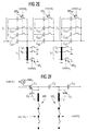
- Fig. 2a shows a resonator arrangement of three connected in series Capacitors C1, C2 and C3 and two inductors 11, 12, the line section between the capacitors C1, C2 or the section between the capacitors Connect C2, C3 to ground.
- Such a resonator arrangement is in the filter stages 15a, 15b, 17a and 17b and the receiving stage, respectively and the transmission stage in the broader sense or the antenna switching and -adjusted.
- Fig. 2b is shown in outline that the inductors 11, 12 of the arrangement of Fig. 2a in a predetermined arrangement each having a plurality of taps, which are connectable via a respective micro-switch to ground.
- the microswitches associated with the inductance 11 are designated in the figure by MS i and are individually controlled via control signals "control i ", while the microswitches assigned to the inductance l 2 are designated by MS j and are controlled via control signals "control j ".
- the microswitches MS i, j divide-depending on the position of the switch-more or less large parts of the inductances 11, 12, so that an adjustment of the frequency characteristic of the resonator arrangement can take place by their activation.
- FIG. 2 c A somewhat modified embodiment of this principle is shown in FIG. 2 c, where the inductors 11, 12 are each subdivided by subinductants by a group of microrelays MR i and MR j driven by drive signals "control i " and “control j ", respectively.
- This circuit in which two ground capacitors C4, C5 are still provided, represents an open circuit, while the embodiment of Fig. 2b is to be addressed as a short circuit.
- Fig. 2d a star-shaped switch configuration is shown, which may take the place of the serial switch arrangement of Fig. 2b or 2c.
- Fig. 2e shows a comparison with FIG 2b modified insofar as here in addition to the inductors 11, 12, the capacitors C 1 , C 2 and C 3 are subdivided by micro-switches in sub-components and tunable by switch operations.
- the switches associated with the capacitors C1 to C3 are designated MS k , MS 1 and MS m and the associated control signals corresponding to "control k ", "control I " and "control m ".
- the sub-inductances of 11 are denoted by l a1 , l b1 , ... and those of 12 to l a2 , l b2 , ..., and analogously, the sub-capacitances of the capacitor C1 are C a1 , C b1 , C c1 , ..., those of the capacitor C2 with C a2 , C b2 , C c2 , ... and those of the capacitor C3 with C a3 , C b3 , C c3 , ... designated.
- a topology is developed by subdividing passive components of a filter or matching region into sub-components by means of microswitches or micro-relays, which has a multiplicity of configurations that can be realized by certain switch actuators.
- FIG. 2f shows a modified embodiment with respect to FIG. 2c in that the capacitor C1 can be changed in its capacitance by a micromotor MM 1 , driven by a control signal "control k ' ".
- the capacitors C2 and C3 can also be designed to be adjustable by means of a micromotor assigned to them with appropriate control.
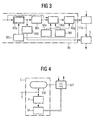
- Fig. 3 shows in the manner of a functional block diagram sketch-like the structure of a tuning control 90 (the reference numeral to the control part 9 of FIG. 1 was ajar) Tuning of a received signal filter stage 17a according to FIG. 1.
- the tuning controller 90 includes a tuning sequence controller 90a, which receives an externally supplied signal, which a requested frequency characteristic of the received signal filtering stage 17a represents.
- the tuning sequencer 90a is connected to the receiving stage 5 connected via an on / off switch 90b, over which they at Reception of the mentioned signal, due to which a vote the receive signal filtering stage 17a is to be made, first the receiving stage 5 switches off. That for the operation of the On / off switch generated signal is via an inverter 90c further a switch configuration calculation stage Supplied 90d and activates this, whereupon this is the above mentioned, a frequency characteristic specifying signal, which is also present at its entrance, receives and caches.
- a topology memory 90e in which the specific, passive components or sub-elements and associated micro-switches or micro-relays and if necessary micromotors formed filter topology of the receive filter stage 17a is stored, and an algorithm memory 90f, in which a corresponding algorithm for determining the concrete switch configuration due to a predetermined Frequency characteristic is stored, calculates the switch configuration calculation stage 90d due to the requested Frequency characteristic to be realized control configuration the microswitch or relay and optionally Micromotors and gives them to a drive signal generator 90g out. This generates - also under access to the topology memory 90e - from this the control signals for every single switch of the overall configuration and performs sequentially to the received signal filtering stage 17a.
- the Output of the last drive signal is by a program end detector 90h detected, the corresponding signal to the tuning sequencer 90a, which then sends the On / off switch 90b for restarting the receiving stage 5 and the switch configuration calculation stage 90d disabled.
- the functions described here are in the practice largely be implemented by software, so that the description given here based on function blocks only to be understood as an illustration of the principle.
- FIG. 4 is sketchy (in a slightly different presentation) an alternative embodiment of the controller shown.
- a control unit C includes a configuration memory M, in which in association with each of a frequency characteristic from a predetermined set of frequency characteristics a predetermined amount of switch position configurations a component / micro switch arrangement of a RF part R / T of a mobile terminal is stored.
- a Input signal line S of the controller C is on the one hand with an on / off switch Sw and on the other hand with a pointer stage P, which in turn is the configuration memory M can address.
- the embodiment of the invention is not as described here Embodiments limited, but also in one Variety of modifications possible.
- microstrip lines for many applications especially appropriate.
- a combination of microswitches with micromotors can also be used with passive components of the same type be useful in the same arrangement, if they become one Reduction of manufacturing costs and construction volume or of the driving effort leads.
- Fig. 5a the case is shown that individually adjustable Voting networks 1, 2, 3 in parallel (see Voting Network 2) or serial (see tuning networks 1, 3) with an active Component are interconnected, which in this case an amplifier. 4 is.
- Fig. 5b shows the case that three individually tunable tuning networks 1, 2, 3 connected to an active component 5 which in this case is a mixer.
- Fig. 5c shows the case that three individually tunable tuning networks 1, 2, 3 connected to an active component 6 which is an oscillator 6.
- FIG. 6 details the structure of a tuning network 101, 102, 103 according to the present invention.
- the tuning network 101 shown as an exemplary embodiment has three capacitors 107, 108, 109 connected serially between an input 121 and an output 122 are connected and their capacity value individually adjustable mechanically is. Furthermore, two inductors or resonators 110, 111 between the connection point between the capacitor 107 and the capacitor 108 and between the capacitor 108th and the capacitor 109 and ground.
- the capacitance values of the capacitors 107, 108, 109 can for example, by moving or turning a metal plate of the capacitors set by a micromotor become.
- the characteristics of the resonators or inductors 110, 111 can mechanically by moving the grounding point be set.
- Each of the adjustable passive components 107, 108, 109, 110, 111 is an electric micromotor 112, 113, 114, 115, 116 associated with the mechanical adjustment of the characteristics of the corresponding components makes.
- the micromotors 112, 113, 114, 115, 116 are controlled by a control unit 217.
- the control unit 117 detects the signal response on the one hand of each matching network 101, 102, 103, in which they receive the signals at the input 121 or the output 122 of each matching network 101, 102, 103 abutment, be supplied to inputs 119, 120, and on the other hand the overall signal response of the RF block by the control unit 117 are supplied with those signals, at the input 125 and the output 126 of the RF block in total concern.
- the control unit 117 can thus the individual passive components 107, 108, 109, 110, 111 of a each mechanically tunable matching network by means of electric micromotors 112, 113, 114, 115 and 116 dependent from the signal response behavior of each matching network and / or the HF block as a whole.
- the corresponding Programming the control unit 117 also online via an air interface 124 and an antenna 123 take place.
- The is called, for example, a mobile phone in which an RF block is installed in accordance with the present invention, can over the Air interface 124 and the antenna 123 online from a Base station are programmed.
- a memory 118 is connected.
- This memory can for example, be a PROM.
- this memory 118 can Setting values for the individual passive components 107, 108, 109, 110, 111, d. H. the corresponding control values for the respectively associated micromotors 112, 113, 114, 115 and 116, respectively be stored permanently.
- a table may be provided, in which which individual adjustment values are required for the passive components are to predetermined signal response of the individual matching networks 101, 102, 103 and the RF block to achieve a total.
- the programmable controller 117 may include the Achieving a specific signal response behavior of the RF block required setting values for the / the mechanical calculate tunable matching network (s) yourself.
- the Values of the mechanically adjustable capacitor, coil and / or resonator selected by driving a micromotor is controlled by software controlled in the control unit 117.
- the adjustment takes place of the customization network specific to the associated active component (transistor, diode, etc.) using a suitable combination of capacitors, coils and resonators.
- the signal response behavior from each RF block in a mobile phone by changing the values of the matching network components adjusted and optimized.
- the control data of the control unit 117 may be stored in memory 118 and later reuse if necessary.
- the matching network shown in FIG represents only one embodiment and a Matching network according to the present invention in general for example, only as a capacitor, but also as one complex combination of a cascade-shaped interconnection of capacitors, coils and resonators can.
- the circuit parameters are predetermined and can no longer be changed.
- the total achieved Performance a compromise of various parameters.
- the working frequency by tuning the matching network be set.
- the RF block can be a wide Covering a frequency range in which, for example, a tunable Broadband Power Amplifier, Broadband Mixer etc. is implemented.
- All amplifiers with low noise may have a design on an optimal noise behavior depending on the Strength of the input signal by tuning the matching network for example, by setting the appropriate Amplification factor can be optimized. This improves, for example the intermodulation property of the circuit.
- a programmable Filter circuit according to the present invention explained.
- the filter circuit shown in Fig. 7a has an input 219 and an output 220 on. Between the entrance 219 and the output 220 are adjustable capacitors 204 in FIG Series switched.
- the capacitors 204 are each of the type whose capacitance value is mechanically adjusted can.
- an electric micromotor 208 associated with a capacitor 204 with adjustable capacity.
- an electric micromotor with more than one capacitor 204 mechanically connected to according to the capacitance values of the capacitors connected to it to adjust.
- each inductance 205 or resonator switched Between the connection points between the individual capacitors 204 and earth is each an inductance 205 or resonator switched. These inductors 205 are also mechanically adjustable, and this is similar to in the capacitors 204 in the illustrated embodiment in each case one electric micromotor 208 each one adjustable Inductance 205 assigned.
- the illustrated in Fig. 7a Filter circuit is, as can be seen, a filter circuit with n steps.
- the filter topology shown in Fig. 7a is the basis of in Fig. 5b shown duplexer.
- the duplexer has two filter circuits 202 and 203, respectively on, by means of a common line from their entrance 219 are connected to an antenna 206 ago.
- Establishing a Frequency Division Multiplexing (FDD) can be the filter circuit 202 with regard to the passive components forming it 204, 205 be set so that their working frequency from the filter circuit 203.
- FDD Frequency Division Multiplexing
- programmable filter circuits shown in Figs. 7a and 7b 201 and 202, 203 are based on a band-pass filter technology. However, it can be seen that the present Invention equally to all other known filter technologies, such as low-pass or high-pass filters and notch filter (band stop) can be applied.
- FIG. 9 shows a section of FIG. 8 which is shown in FIG. 8 is denoted by a).
- the mechanical shown in Fig. 9 adjustable capacitor 204 consists essentially of a Metal plate 211 sandwiched over a dielectric 210, which in turn is over a printed circuit board (PCB, Printed Circuit Board) 209 is located.
- PCB printed circuit board
- the electric micromotor 208 is thereby controlled by a control unit 217 controlled. As symbolically by arrows in Fig. 9 is shown, the control unit 217 about it.
- the control unit 217 performs this setting of the individual Components so that the filter circuit total between its input 219 and its output 220 or 220 'a predetermined Frequency characteristic has. To do this, the control unit 217 as information supplied the signals to the the input 219 or at the output 220, 220 'of the filter circuit abut, as also indicated by arrows symbolically in Fig. 3 is shown. By means of the supplied signals from Input 219 or from the output 220, 220 ', the control unit 217 determine the frequency characteristic of the filter circuit and determine if this actual frequency characteristic has a Setpoint frequency characteristic coincides.
- control unit 217 may itself set the drive values for the electric micromotors 208, the needed to achieve a predetermined frequency characteristic become.
- the frequency characteristic to be set can be found in the Control unit 217 itself be stored or online For example, by means of an air interface in the case of Mobile device to the control unit 217 are transmitted.
- a PROM memory 218 is provided.
- the PROM memory 218 can set values or control values for the electric micromotors 208 and optionally predetermined Frequency characteristics for the filter circuit in total in shape a table permanently stored.
- the control unit 217 to achieve a predetermined frequency characteristic the filter circuit to the stored in the PROM 218 Access table.
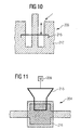
- Fig. 10 shows a detail of Fig. 8, in Fig. 8 with b) is designated.
- the passive component is a resonator 205.
- a short-circuit conductor 205 driven by an electric micromotor 208 with respect to its position with respect to the ground 212 can through the control unit 217 drives the characteristics of the resonator 205 are set.
- Fig. 11 shows a further embodiment of a mechanical adjustable capacitor 204.
- any known circuit topology the one filter function or duplexer function to serve as a basis for the present invention can.
- the characteristics of the adjustable (programmable) capacitor, the inductance or a resonator in the circuit topology by a Micro motor to be changed, the. again electrically a control unit is controlled.
- the characteristic values such as the capacity or the resonance value, be changed so that the desired Filter or duplexer characteristic with a desired center frequency and bandwidth is obtained.
Landscapes
- Engineering & Computer Science (AREA)
- Computer Networks & Wireless Communication (AREA)
- Signal Processing (AREA)
- Transceivers (AREA)
- Filters And Equalizers (AREA)
- Control Of Motors That Do Not Use Commutators (AREA)
Description
- Fig. 1
- ein stark vereinfachtes Funktions-Blockschaltbild eines Mobilfunk-Endgerätes zur Erläuterung der Erfindung anhand einer Ausführungsform,
- Fig. 2a
- ein Prinzipschaltbild einer Resonatorschaltung, wie sie in einem der Filterbausteine bzw. im Duplexer des Mobilfunk-Endgerätes nach Fig. 1 eingesetzt wird,
- die Figuren 2b bis 2e
- verschiedene Realisierungen der Schaltung nach Fig. 2a gemäß Ausführungsformen der Erfindung unter Einsatz von Mikroschaltern bzw. Mikrorelais,
- die Figuren 2f und 2g
- modifizierte Ausführungsformen einer abstimmbaren Resonatorschaltung, bei denen neben Mikrorelais bzw. Mikroschaltern auch Mikromotoren vorgesehen sind,
- Fig. 3
- ein Funktions-Blockschaltbild einer Steueranordnung zur Abstimmung einer Filterstufe des Mobilfunk-Endgerätes nach Fig. 1,
- Fig. 4
- eine Skizze der Steuerung gemäß einer weiteren Ausführungsform,
- Fig. 5a - 5c
- schematische Schaltbilder von Ausführungsbeispielen der vorliegenden Erfindung, in denen abstimmbare Anpassungsnetzwerke mit einem Verstärker (Fig. 5a), einem Mischer (Fig. 5b) bzw. einem Oszillator (Fig. 5c) verbunden werden,
- Fig. 6
- eine detaillierte Ansicht eines abstimmbaren Anpassungsnetzwerkes gemäß der vorliegenden Erfindung,
- Fig. 7a
- einen schematischen Schaltplan einer erfindungsgemäßen programmierbaren Filterschaltung,
- Fig. 7b
- einen Duplexer, der zwei programmierbare Filterschaltungen aufweist, deren Bauteile so eingestellt sind, daß die Filterschaltungen insgesamt verschiedene Frequenzkennlinien aufweisen,
- Fig. 8
- ein Ausführungsbeispiel für die Realisierung einer Filterschaltung bestehend aus Kondensatoren und Induktivitäten/Resonatoren, deren Kennwerte mechanisch eingestellt werden können,
- Fig. 9
- einen Ausschnitt von Fig. 8, der in Fig. 2 mit a) bezeichnet ist, wobei in Fig. 9 darüber hinaus die Ansteuerung zur Einstellung der Kennwerte eines Kondensators dargestellt ist,
- Fig. 10
- einen Ausschnitt von Fig. 8, welcher die Draufsicht eines Leitungsresonators zeigt, der durch einen Kurzschlußschieber in seinen elektrischen Eigenschaften geändert wird, der in Fig. 8 mit b) bezeichnet ist, und
- Fig. 11
- ein weiteres Ausführungsbeispiel zur Schaffung eines Kondensators, dessen Kapazitätswert mechanisch durch einen Mikromotor verstellt werden kann.
- 1
- Mobilfunk-Endgerät
- 3
- Basisband-Block
- 5
- Empfangsstufe
- 7
- Sendestufe
- 9
- Steuerstufe
- 11
- Duplexer
- 13
- Antenne
- 15a, 15b
- Sendesignal-Filterstufe
- 17a, 17b
- Empfangssignal-Filterstufe
- C1, C2, C3, C4, C5
- Kondensator
- 11, 12
- Induktivität
- MSi, j, k, l, m
- Mikroschalter
- MM1, MM2
- Mikromotor
- 90
- Abstimmsteuerung
- 90a
- Abstimmablaufsteuerung
- 90b
- Ein-/Ausschalter
- 90c
- Inverter
- 90d
- Schalterkonfigurations-Berechnungsstufe
- 90f
- Algorithmenspeicher
- 90g
- Ansteuersignalgenerator
- 90h
- Programmende-Detektor
- C
- Steuerung
- M
- Konfigurationenspeicher
- P
- Zeigerstufe
- R/T
- HF-Teil
- S
- Steuersignalleitung
- Sw
- Ein-/Ausschalter
- 101
- Anpassungsnetzwerk
- 102
- Anpassungsnetzwerk
- 103
- Anpassungsnetzwerk
- 104
- aktives Bauteil (Verstärker)
- 105
- aktives Bauteil (Mischer)
- 106
- aktives Bauteil (Oszillator)
- 107
- Kondensator
- 108
- Kondensator
- 109
- Kondensator
- 110
- Induktivität (Spule)
- 111
- Induktivität (Spule)
- 112
- Mikromotor
- 113
- Mikromotor
- 114
- Mikromotor
- 115
- Mikromotor
- 116
- Mikromotor
- 117
- Steuereinheit
- 118
- Speicher
- 119
- Eingang der Steuereinheit
- 120
- Eingang der Steuereinheit
- 121
- Eingangsanschluß des Anpassungsnetzwerks
- 122
- Ausgangsanschluß des Abstimmnetzwerks
- 123
- Antenne
- 124
- Luftschnittstelle
- 125
- Eingang der Steuereinheit
- 126
- Eingang der Steuereinheit
- 201
- programmierbare Filterschaltung
- 202, 203
- programmierbare Filterschaltungen des Duplexers
- 204
- einstellbarer Kondensator
- 205
- einstellbare Induktivität/Resonator
- 206
- Antenne
- 207
- Metallscheibe
- 208
- elektrischer Mikromotor
- 209
- gedruckte Schaltungsplatine
- 210
- Dielektrikum
- 211
- Metallscheibe
- 212
- Erdungspotential
- 215
- Metallplatte
- 216
- Dielektrikum
Claims (17)
- Mobilfunk-Endgerät, aufweisenddie jeweils eine Anordnung passiver Bauelemente aufweisen, welcher eine Mehrzahl von elektrostatisch-mechanischen Mikroschaltern (MSi-MSm) bzw. Mikrorelais (MRi, MRj) zugeordnet ist und die durch Ansteuerung einer vorbestimmten Konfiguration der Mikroschalter bzw. Mikrorelais in mindestens je einem Funktionsparameter, insbesondere der Frequenzcharakteristik, einstellbar ist,eine Sendestufe (7, 15a, 15b),eine Empfangsstufe (5, 17a, 17b),eine Antennenumschalt- und -anpaßstufe (11),
dadurch gekennzeichnet, daß eine über eine Luftschnittstelle (124) programmierbare Steuereinheit (9; 90; C) zur Ansteuerung der Mikroschalter- bzw. Mikrorelaiskonfiguration zur Einstellung vorbestimmter Werte des Funktions-parameters bzw. der Funktionsparameter vorhanden ist. - Mobilfunk-Endgerät nach Anspruch 1,
dadurch gekennzeichnet, dass mindestens eine der Sendestufe (7, 15a, 15b), Empfangsstufe (5, 17a, 17b), und Antennenumschalt- und -anpaßstufe (11) eine Mehrzahl von Mikromotoren zur mechanischen Verstellung passiver Bauelemente aufweist, wobei die Mikromotoren (MM1, MM2) in Steuerverbindung mit der Steuereinheit stehen. - Mobilfunk-Endgerät nach Anspruch 2,
dadurch gekennzeichnet, daß die Steuereinheit (90; C) einen Ein-/Ausschalter (90b; Sw) für die Sende- und die Empfangsstufe aufweist und derart ausgebildet ist, daß jeweils vor Ausgabe eines Ansteuersignals an die Mikroschalter- bzw. Mikrorelaiskonfiguration und wahlweise einen Mikromotor ein Ausschaltsignal an den Ein-/Ausschalter zur Deaktivierung der Sende- und/oder Empfangsstufe (5; R/T) ausgegeben wird. - Mobilfunk-Endgerät nach Anspruch 3,
dadurch gekennzeichnet, daß die Steuereinheit (90) eine mit dem Ein-/Ausschalter (90b) verbundene Programmende-Erfassungseinheit (90h) aufweist, die nach Beendigung eines Programmablaufes zur Einstellung eines oder mehrerer Funktionsparameter ein Einschaltsignal an den Ein-/Ausschalter zur Aktivierung der Sende- und/oder Empfangsstufe (5) ausgibt. - Mobilfunk-Endgerät nach einem der vorangehenden Ansprüche,
dadurch gekennzeichnet, daß mindestens ein Teil der Mikroschalter bzw. Mikrorelais mit den jeweils zugehörigen passiven Bauelementen auf ein und demselben Substrat, insbesondere einem Substrat mit hoher Dielektrizitätskonstante, integriert ist. - Mobilfunk-Endgerät nach Anspruch 2,
dadurch gekennzeichnet, daß mindestens ein Teil der Mikromotoren mit den jeweils zugehörigen passiven Bauelementen auf ein und demselben Substrat, insbesondere einem Substrat mit hoher Dielektrizitätskonstante, integriert ist. - Mobilfunk-Endgerät nach einem der vorangehenden Ansprüche,
dadurch gekennzeichnet, daß die Steuereinheit (90)aufweist.einen Topologiespeicher (90e) zur Speicherung der Topologie der den oder die Funktionsparameter bestimmenden Anordnung aus passiven Bauelementen und Mikroschaltern bzw. Mikrorelais,einen Algorithmenspeicher (90f) zur Speicherung eines Berechnungs-Algorithmus für vorbestimmte Werte jedes Funktionsparameters aufgrund von Topologieelementen undeine Berechnungsstufe (90d) zur Ermittlung der zur Realisierung des vorbestimmten Wertes oder der vorbestimmten Werte anzusteuernden Mikroschalter bzw. Mikrorelais der Konfiguration aufgrund des gespeicherten Berechnungsalgorithmus - Mobilfunk-Endgerät nach Anspruch 7,
dadurch gekennzeichnet, daß der Topologiespeicher (90e) zur Speicherung der Position sowie eines den möglichen Ansteuerstufen jedes Mikromotors entsprechenden Topologie-Äquivalents und die Berechnungsstufe (90d) zur Berechnung des zur Realisierung eines vorbestimmten Wertes des Funktionsparameters auszugebenden Ansteuersignals für jeden Mikromotor ausgebildet ist. - Mobilfunk-Endgerät nach einem der Ansprüche 1 bis 7,
dadurch gekennzeichnet, daß die Steuereinheit (C)einen als Lookup-Table ausgebildeten Konfigurationenspeicher (M) zur Speicherung einer Mehrzahl von Schaltstellungskonfigurationen der Mikroschalter bzw. Mikrorelais jeweils in Zuordnung zu einem Wert eines Funktionsparameters oder einem Werte-Vektor mehrerer Funktionsparameter undeine Zeigerstufe (P) zur Adressierung des Konfigurationenspeichers in Abhängigkeit von einem programmierbaren Wert oder Werte-Vektor aufweist. - Mobilfunk-Endgerät nach Anspruch 9,
dadurch gekennzeichnet, daß der Konfigurationenspeicher (M) zur Speicherung von kombinierten Schalterstellungs- und Motoransteuerungs-Konfigurationen einer Bauelementanordnung ausgebildet ist, in der neben Mikroschaltern bzw. Mikrorelais Mikromotoren zur Verstellung passiver Bauelemente vorgesehen sind. - Programmierbarer HF-Block für Mobilfunk-Anwendungen, aufweisenddadurch gekennzeichnet, daß eine über eine Luftschnittstelle (124) programmierbare Steuereinheit (117) vorhanden ist, die das mechanisch abstimmbare Anpassungsnetzwerk (101, 102, 103) so einstellt, daß der HF-Block insgesamt vorbestimmte Eigenschaften hinsichtlich seines Signalantwortverhaltens aufweist.ein aktives Bauteil (104, 105, 106),wenigstens ein mechanisch abstimmbares Anpassungsnetzwerk (101, 102, 103), das individuell einstellbare passive Bauteile (107, 108, 109, 110, 111) aufweist und mit dem aktiven Bauteil (104, 105, 106) verbunden ist,
- Programmierbarer HF-Block nach Anspruch 11,
dadurch gekennzeichnet, dass jeweils einem einstellbaren passiven Bauteil (107, 108, 109, 110, 111) ein elektrischer Mikromotor (112, 113, 114, 115, 116) zugeordnet ist und die programmierbare Steuereinheit (117) die Mikromotoren (112, 113, 114, 115, 116) zur Einstellung des mechanisch abstimmbaren Anpassungsnetzwerks (101, 102, 103) ansteuert. - Programmierbarer HF-Block nach Anspruch 12,
dadurch gekennzeichnet, daß die Mikromotoren (112, 113, 114, 115, 116) nur während der Zeitdauer der Einstellung des mechanisch abstimmbaren Anpassungsnetzwerks (101, 102, 103) aktiviert sind und außerhalb dieser Zeitdauer die elektrische Versorgung der Mikromotoren (112, 113, 114, 115, 116) abgeschaltet wird. - Programmierbarer HF-Block nach einem der vorhergehenden Ansprüche,
dadurch gekennzeichnet, daß ein Speicher (118) mit der programmierbaren Steuereinheit (117) verbunden ist, in dem Einstellwerte für das mechanisch abstimmbare Anpassungsnetzwerk (101, 102, 103) und/oder vorbestimmte Eigenschaften des HF-Blocks hinsichtlich seines Signalanwortverhaltens dauerhaft abgelegt sind. - Programmierbarer HF-Block nach Anspruch 14,
dadurch gekennzeichnet, daß in dem Speicher (118) eine Tabelle angelegt ist, die die zur Erzielung eines bestimmten Signalanwortverhaltens des HF-Blocks erforderlichen Einstellwerte für das mechanisch abstimmbare Anpassungsnetzwerk (101, 102, 103) wiedergibt. - Programmierbarer HF-Block nach einem der vorhergehenden Ansprüche,
dadurch gekennzeichnet, daß die programmierbare Steuereinheit (117) den HF-Block hinsichtlich seiner Eigenschaften betreffend der Arbeitsfrequenz, der Bandbreite, der Verstärkungsleistung und/oder des Rauschverhaltens einstellt. - Programmierbarer HF-Block nach einem der vorhergehenden Ansprüche,
dadurch gekennzeichnet, daß die programmierbare Steuereinheit (117) die zur Erzielung eines bestimmten Signalanwortverhaltens des HF-Blocks erforderlichen Einstellwerte für das mechanisch abstimmbare Anpassungsnetzwerk (101, 102, 103) selbst berechnet.
Applications Claiming Priority (7)
| Application Number | Priority Date | Filing Date | Title |
|---|---|---|---|
| DE19844142 | 1998-09-25 | ||
| DE19844143A DE19844143A1 (de) | 1998-09-25 | 1998-09-25 | Programmierbare Filterschaltung für Mobilfunkanwendungen |
| DE19844143 | 1998-09-25 | ||
| DE19844142A DE19844142C2 (de) | 1998-09-25 | 1998-09-25 | Programmierbarer HF-Block |
| DE19919368 | 1999-04-28 | ||
| DE19919368A DE19919368B4 (de) | 1999-04-28 | 1999-04-28 | Mobilfunk-Endgerät und Verfahren zu dessen Betrieb |
| PCT/DE1999/003079 WO2000019626A1 (de) | 1998-09-25 | 1999-09-24 | Programmierbares mobilfunk-endgerät |
Publications (2)
| Publication Number | Publication Date |
|---|---|
| EP1116338A1 EP1116338A1 (de) | 2001-07-18 |
| EP1116338B1 true EP1116338B1 (de) | 2004-11-24 |
Family
ID=27218702
Family Applications (1)
| Application Number | Title | Priority Date | Filing Date |
|---|---|---|---|
| EP99955797A Expired - Lifetime EP1116338B1 (de) | 1998-09-25 | 1999-09-24 | Programmierbares mobilfunk-endgerät |
Country Status (7)
| Country | Link |
|---|---|
| US (2) | US7570973B1 (de) |
| EP (1) | EP1116338B1 (de) |
| JP (1) | JP2002526969A (de) |
| CN (1) | CN1242560C (de) |
| AU (1) | AU1261800A (de) |
| DE (1) | DE59911153D1 (de) |
| WO (1) | WO2000019626A1 (de) |
Families Citing this family (17)
| Publication number | Priority date | Publication date | Assignee | Title |
|---|---|---|---|---|
| WO2000019626A1 (de) * | 1998-09-25 | 2000-04-06 | Siemens Aktiengesellschaft | Programmierbares mobilfunk-endgerät |
| US7065342B1 (en) | 1999-11-23 | 2006-06-20 | Gofigure, L.L.C. | System and mobile cellular telephone device for playing recorded music |
| FI109382B (fi) * | 2000-06-27 | 2002-07-15 | Nokia Corp | Sovituspiiri |
| DE10052719B4 (de) * | 2000-10-24 | 2004-08-26 | Siemens Ag | Filter für elektromagnetisch übertragene Signale |
| US7602740B2 (en) * | 2001-12-10 | 2009-10-13 | Qst Holdings, Inc. | System for adapting device standards after manufacture |
| ATE523974T1 (de) * | 2004-03-04 | 2011-09-15 | St Ericsson Sa | Basisbandprozessor und verfahren zum senden von befehlen zu einem hochfrequenz-subsystem und den basisbandprozessor enthaltnede funktelekommunikationsvorrichtung |
| US20160294274A1 (en) * | 2004-06-17 | 2016-10-06 | Ctm Magnetics, Inc. | Distributed gap inductor, notch filter apparatus and method of use thereof |
| US7593696B2 (en) * | 2005-02-10 | 2009-09-22 | Alcatel-Lucent Usa Inc. | Tunable radio frequency filter |
| JP4621155B2 (ja) * | 2006-02-28 | 2011-01-26 | 株式会社エヌ・ティ・ティ・ドコモ | 可変フィルタ |
| JP4847937B2 (ja) * | 2007-09-10 | 2011-12-28 | 株式会社エヌ・ティ・ティ・ドコモ | 信号選択装置 |
| JP5086873B2 (ja) * | 2007-10-31 | 2012-11-28 | 株式会社エヌ・ティ・ティ・ドコモ | 送受共用器、送受信装置 |
| US8072297B2 (en) * | 2008-12-29 | 2011-12-06 | Qualcomm Incorporated | Apparatus and method for improving channel filter selectivity and performance using voltage variable impedance elements |
| US8680947B1 (en) | 2009-07-24 | 2014-03-25 | Rf Micro Devices, Inc. | Passive multi-band duplexer |
| US9246536B2 (en) * | 2009-12-03 | 2016-01-26 | Rf Micro Devices, Inc. | Duplexer with active temperature compensation |
| US8838045B2 (en) | 2009-12-03 | 2014-09-16 | Rf Micro Devices, Inc. | Sub-band duplexer with active frequency tuning |
| US20130156074A1 (en) * | 2011-12-14 | 2013-06-20 | Aviacomm Inc. | Wideband rf front-end |
| CN109495119B (zh) * | 2018-12-28 | 2021-08-10 | Tcl移动通信科技(宁波)有限公司 | 一种射频开关控制方法、装置、移动终端及存储介质 |
Family Cites Families (21)
| Publication number | Priority date | Publication date | Assignee | Title |
|---|---|---|---|---|
| GB955223A (en) | 1961-08-30 | 1964-04-15 | Siemens Ag | Automatic control device for a radio transmitter |
| DE3010707A1 (de) | 1980-03-20 | 1981-09-24 | Dr. Wächtler GmbH, 2000 Hamburg | Verfahren und anordnung zur rechnergesteuerten abstimmung von vorselektrionskreisen bei hochfrequenzempfaengern |
| DE3830100A1 (de) | 1988-09-05 | 1990-03-15 | Olympia Aeg | Verfahren zur optimierung der abstimmung eines senders und anordnung zum durchfuehren des verfahrens |
| JP2600472B2 (ja) | 1990-10-19 | 1997-04-16 | 株式会社村田製作所 | 帯域通過フィルタのための自動同調装置 |
| US5164688A (en) * | 1991-05-31 | 1992-11-17 | Hughes Aircraft Company | Miniature microwave and millimeter wave tuner |
| US5231341A (en) | 1991-09-18 | 1993-07-27 | Samsung Electronics Co., Ltd. | Limiter circuit of servo motor control apparatus |
| FI91469C (fi) | 1992-03-31 | 1994-06-27 | Nokia Telecommunications Oy | Menetelmä RF-kaistanpäästösuodattimen virittämiseksi |
| JP2500748B2 (ja) | 1993-05-14 | 1996-05-29 | 日本電気株式会社 | 静電マイクロモ―タ |
| US5619061A (en) | 1993-07-27 | 1997-04-08 | Texas Instruments Incorporated | Micromechanical microwave switching |
| US5526172A (en) | 1993-07-27 | 1996-06-11 | Texas Instruments Incorporated | Microminiature, monolithic, variable electrical signal processor and apparatus including same |
| DE4329705A1 (de) | 1993-09-02 | 1995-03-09 | Froehlich Reimar Dr Ing | Schaltungsanordnung für mikrorechnersteuerbare Induktivitäten, Kapazitäten und L/C-Schaltungen |
| US5689825A (en) | 1995-07-28 | 1997-11-18 | Motorola, Inc. | Method and apparatus for downloading updated software to portable wireless communication units |
| US5696662A (en) | 1995-08-21 | 1997-12-09 | Honeywell Inc. | Electrostatically operated micromechanical capacitor |
| SE507698C2 (sv) | 1996-07-10 | 1998-07-06 | Allgon Ab | Förfarande och system för avstämning resonansmoduler |
| US6246727B1 (en) * | 1996-07-10 | 2001-06-12 | Allgon Ab | Method and system for tuning resonance modules |
| US5994816A (en) * | 1996-12-16 | 1999-11-30 | Mcnc | Thermal arched beam microelectromechanical devices and associated fabrication methods |
| EP1031188A1 (de) * | 1997-11-03 | 2000-08-30 | Harris Corporation | Ein feldprogrammierbares funkfrequenzkommunikationssystem mit einer konfigurierbaren if schaltung und zugehöriges verfahren |
| US6127908A (en) * | 1997-11-17 | 2000-10-03 | Massachusetts Institute Of Technology | Microelectro-mechanical system actuator device and reconfigurable circuits utilizing same |
| DE19818515C2 (de) | 1998-04-24 | 2001-02-01 | Siemens Ag | Verfahren zum Programmieren eines programmierbaren Funkgeräts sowie ein entsprechendes programmierbares Funkgerät |
| WO2000019626A1 (de) * | 1998-09-25 | 2000-04-06 | Siemens Aktiengesellschaft | Programmierbares mobilfunk-endgerät |
| JP4156723B2 (ja) | 1998-09-30 | 2008-09-24 | 株式会社ヨシカワ | 粉粒体排出シュート |
-
1999
- 1999-09-24 WO PCT/DE1999/003079 patent/WO2000019626A1/de not_active Ceased
- 1999-09-24 CN CNB998137170A patent/CN1242560C/zh not_active Expired - Fee Related
- 1999-09-24 EP EP99955797A patent/EP1116338B1/de not_active Expired - Lifetime
- 1999-09-24 AU AU12618/00A patent/AU1261800A/en not_active Abandoned
- 1999-09-24 JP JP2000573012A patent/JP2002526969A/ja active Pending
- 1999-09-24 DE DE59911153T patent/DE59911153D1/de not_active Expired - Fee Related
- 1999-09-24 US US09/787,868 patent/US7570973B1/en not_active Expired - Fee Related
-
2009
- 2009-06-25 US US12/491,509 patent/US8045933B2/en not_active Expired - Fee Related
Also Published As
| Publication number | Publication date |
|---|---|
| CN1242560C (zh) | 2006-02-15 |
| US20090325564A1 (en) | 2009-12-31 |
| DE59911153D1 (de) | 2004-12-30 |
| US8045933B2 (en) | 2011-10-25 |
| AU1261800A (en) | 2000-04-17 |
| EP1116338A1 (de) | 2001-07-18 |
| US7570973B1 (en) | 2009-08-04 |
| CN1328722A (zh) | 2001-12-26 |
| WO2000019626A1 (de) | 2000-04-06 |
| JP2002526969A (ja) | 2002-08-20 |
Similar Documents
| Publication | Publication Date | Title |
|---|---|---|
| EP1116338A1 (de) | Programmierbares mobilfunk-endgerät | |
| DE102013202124B4 (de) | Einstellbares Impedanzanpassungsnetz | |
| DE102016114663B4 (de) | Multiplexer | |
| DE102014119624A1 (de) | Abstimmbarer Hochfrequenzfilter mit niedriger Dämpfung | |
| DE69216917T2 (de) | Abstimmbare Resonatoranordnung | |
| DE60222592T2 (de) | Antennenweiche und deren Verwendung in einem mobilen Kommunikationsgerät | |
| DE69506592T2 (de) | Veränderliches Filter | |
| DE102013202113A1 (de) | Einstellbares Impedanzanpassungsnetz | |
| WO2005122390A2 (de) | Oszillator | |
| EP1456859A1 (de) | Induktives bauteil | |
| EP1352482B1 (de) | Elektrisches schaltmodul, schaltmodulanordnung und verwendung des schaltmoduls und der schaltmodulanordnung | |
| DE19919368B4 (de) | Mobilfunk-Endgerät und Verfahren zu dessen Betrieb | |
| EP0196130B1 (de) | Schaltungsanordnung der Eingangsstufen eines Fernsehtuners | |
| WO2009141358A1 (de) | Schaltung zur impedanzanpassung | |
| EP1687908A1 (de) | Verfahren und vorrichtung zum verbinden der sende- und empfangseinrichtungen von multiband-/multimode-funkgeräten mit einer oder mehreren teilweise genutzten antennen | |
| DE19844142C2 (de) | Programmierbarer HF-Block | |
| DE102009033673B4 (de) | Adaptiv abstimmbares Anpassnetzwerk mit verbessertem linearen Verhalten | |
| EP0814571A2 (de) | Rundfunkempfänger mit integrierter Fernsprecheinrichtung | |
| DE19930195C2 (de) | Schaltung zum Verstärken eines Hochfrequenzsignals aus zumindest zwei Hochfrequenzbereichen, 2-Band-Empfänger mit der Schaltung, 2-Band-Mobilfunkvorrichtung mit dem Empfänger und Verwendung einer Serienschaltung aus einem kapazitiven Element und einer Hochfrequenzleitung in einer Verstärkerschaltung | |
| EP0255174A2 (de) | Rundfunkempfänger | |
| DE19628014C2 (de) | Frequenzweiche für Lautsprecherboxen sowie Lautsprecherbox mit einer solchen Frequenzweiche | |
| DE2220749B2 (de) | Verfahren und Vorrichtung zur Anpassung einer Last, insbesondere einer Antenne, an eine vorgegebene Quellenimpedanz | |
| DE112023004521T5 (de) | Abstimmbarer akustischer oberflächenwellenresonator | |
| DE10053216A1 (de) | Spannungsgesteuerter Oszillator, insbesondere für Mobilfunkgeräte | |
| DE10202757B4 (de) | Antennenvorrichtung |
Legal Events
| Date | Code | Title | Description |
|---|---|---|---|
| PUAI | Public reference made under article 153(3) epc to a published international application that has entered the european phase |
Free format text: ORIGINAL CODE: 0009012 |
|
| 17P | Request for examination filed |
Effective date: 20010312 |
|
| AK | Designated contracting states |
Kind code of ref document: A1 Designated state(s): AT BE CH CY DE DK ES FI FR GB GR IE IT LI LU MC NL PT SE |
|
| 17Q | First examination report despatched |
Effective date: 20031106 |
|
| GRAJ | Information related to disapproval of communication of intention to grant by the applicant or resumption of examination proceedings by the epo deleted |
Free format text: ORIGINAL CODE: EPIDOSDIGR1 |
|
| GRAP | Despatch of communication of intention to grant a patent |
Free format text: ORIGINAL CODE: EPIDOSNIGR1 |
|
| GRAP | Despatch of communication of intention to grant a patent |
Free format text: ORIGINAL CODE: EPIDOSNIGR1 |
|
| RBV | Designated contracting states (corrected) |
Designated state(s): DE FR GB |
|
| GRAS | Grant fee paid |
Free format text: ORIGINAL CODE: EPIDOSNIGR3 |
|
| GRAA | (expected) grant |
Free format text: ORIGINAL CODE: 0009210 |
|
| AK | Designated contracting states |
Kind code of ref document: B1 Designated state(s): DE FR GB |
|
| REG | Reference to a national code |
Ref country code: GB Ref legal event code: FG4D Free format text: NOT ENGLISH |
|
| REF | Corresponds to: |
Ref document number: 59911153 Country of ref document: DE Date of ref document: 20041230 Kind code of ref document: P |
|
| REG | Reference to a national code |
Ref country code: IE Ref legal event code: FG4D Free format text: GERMAN |
|
| GBT | Gb: translation of ep patent filed (gb section 77(6)(a)/1977) |
Effective date: 20050301 |
|
| REG | Reference to a national code |
Ref country code: IE Ref legal event code: FD4D |
|
| PLBE | No opposition filed within time limit |
Free format text: ORIGINAL CODE: 0009261 |
|
| STAA | Information on the status of an ep patent application or granted ep patent |
Free format text: STATUS: NO OPPOSITION FILED WITHIN TIME LIMIT |
|
| ET | Fr: translation filed | ||
| 26N | No opposition filed |
Effective date: 20050825 |
|
| PGFP | Annual fee paid to national office [announced via postgrant information from national office to epo] |
Ref country code: DE Payment date: 20061120 Year of fee payment: 8 |
|
| PGFP | Annual fee paid to national office [announced via postgrant information from national office to epo] |
Ref country code: FR Payment date: 20070918 Year of fee payment: 9 |
|
| PG25 | Lapsed in a contracting state [announced via postgrant information from national office to epo] |
Ref country code: DE Free format text: LAPSE BECAUSE OF NON-PAYMENT OF DUE FEES Effective date: 20080401 |
|
| REG | Reference to a national code |
Ref country code: FR Ref legal event code: ST Effective date: 20090529 |
|
| PG25 | Lapsed in a contracting state [announced via postgrant information from national office to epo] |
Ref country code: FR Free format text: LAPSE BECAUSE OF NON-PAYMENT OF DUE FEES Effective date: 20080930 |
|
| REG | Reference to a national code |
Ref country code: GB Ref legal event code: 732E Free format text: REGISTERED BETWEEN 20140807 AND 20140813 |
|
| REG | Reference to a national code |
Ref country code: GB Ref legal event code: 732E Free format text: REGISTERED BETWEEN 20140814 AND 20140820 |
|
| PGFP | Annual fee paid to national office [announced via postgrant information from national office to epo] |
Ref country code: GB Payment date: 20170829 Year of fee payment: 19 |
|
| GBPC | Gb: european patent ceased through non-payment of renewal fee |
Effective date: 20180924 |
|
| PG25 | Lapsed in a contracting state [announced via postgrant information from national office to epo] |
Ref country code: GB Free format text: LAPSE BECAUSE OF NON-PAYMENT OF DUE FEES Effective date: 20180924 |