EP1116064B1 - Verfahren und vorrichtung zur formung des intensitätsprofils eines laserstrahls - Google Patents
Verfahren und vorrichtung zur formung des intensitätsprofils eines laserstrahls Download PDFInfo
- Publication number
- EP1116064B1 EP1116064B1 EP00942048A EP00942048A EP1116064B1 EP 1116064 B1 EP1116064 B1 EP 1116064B1 EP 00942048 A EP00942048 A EP 00942048A EP 00942048 A EP00942048 A EP 00942048A EP 1116064 B1 EP1116064 B1 EP 1116064B1
- Authority
- EP
- European Patent Office
- Prior art keywords
- oaslm
- intensity
- light modulator
- laser beam
- intensity profile
- Prior art date
- Legal status (The legal status is an assumption and is not a legal conclusion. Google has not performed a legal analysis and makes no representation as to the accuracy of the status listed.)
- Expired - Lifetime
Links
- 238000000034 method Methods 0.000 title claims abstract description 12
- 238000007493 shaping process Methods 0.000 title claims description 17
- 238000005286 illumination Methods 0.000 claims abstract description 9
- 230000005577 local transmission Effects 0.000 claims abstract description 9
- 230000003287 optical effect Effects 0.000 claims description 17
- 238000003384 imaging method Methods 0.000 claims description 11
- 230000008569 process Effects 0.000 claims description 7
- 239000004973 liquid crystal related substance Substances 0.000 claims description 6
- 230000008859 change Effects 0.000 claims description 4
- 230000005540 biological transmission Effects 0.000 description 5
- 238000012545 processing Methods 0.000 description 4
- 239000000463 material Substances 0.000 description 3
- 230000008901 benefit Effects 0.000 description 2
- 238000006243 chemical reaction Methods 0.000 description 2
- 239000013078 crystal Substances 0.000 description 2
- 230000001419 dependent effect Effects 0.000 description 2
- 238000009826 distribution Methods 0.000 description 2
- 238000005516 engineering process Methods 0.000 description 2
- 239000000835 fiber Substances 0.000 description 2
- 238000005305 interferometry Methods 0.000 description 2
- 238000004519 manufacturing process Methods 0.000 description 2
- 230000003068 static effect Effects 0.000 description 2
- 230000007704 transition Effects 0.000 description 2
- 241001270131 Agaricus moelleri Species 0.000 description 1
- 241000834287 Cookeolus japonicus Species 0.000 description 1
- 239000004988 Nematic liquid crystal Substances 0.000 description 1
- 239000004990 Smectic liquid crystal Substances 0.000 description 1
- 230000004913 activation Effects 0.000 description 1
- 230000003044 adaptive effect Effects 0.000 description 1
- 230000032683 aging Effects 0.000 description 1
- 230000003321 amplification Effects 0.000 description 1
- 238000013459 approach Methods 0.000 description 1
- 230000001427 coherent effect Effects 0.000 description 1
- 238000004891 communication Methods 0.000 description 1
- 230000001276 controlling effect Effects 0.000 description 1
- 230000008878 coupling Effects 0.000 description 1
- 238000010168 coupling process Methods 0.000 description 1
- 238000005859 coupling reaction Methods 0.000 description 1
- 230000008021 deposition Effects 0.000 description 1
- 238000011161 development Methods 0.000 description 1
- 230000018109 developmental process Effects 0.000 description 1
- 239000011521 glass Substances 0.000 description 1
- 238000010438 heat treatment Methods 0.000 description 1
- 239000002184 metal Substances 0.000 description 1
- 238000003199 nucleic acid amplification method Methods 0.000 description 1
- 239000013307 optical fiber Substances 0.000 description 1
- 230000002093 peripheral effect Effects 0.000 description 1
- 230000000704 physical effect Effects 0.000 description 1
- 229920000642 polymer Polymers 0.000 description 1
- 230000005855 radiation Effects 0.000 description 1
- 230000001105 regulatory effect Effects 0.000 description 1
- 230000003595 spectral effect Effects 0.000 description 1
- 238000010792 warming Methods 0.000 description 1
- 238000003466 welding Methods 0.000 description 1
Images


Classifications
-
- G—PHYSICS
- G02—OPTICS
- G02F—OPTICAL DEVICES OR ARRANGEMENTS FOR THE CONTROL OF LIGHT BY MODIFICATION OF THE OPTICAL PROPERTIES OF THE MEDIA OF THE ELEMENTS INVOLVED THEREIN; NON-LINEAR OPTICS; FREQUENCY-CHANGING OF LIGHT; OPTICAL LOGIC ELEMENTS; OPTICAL ANALOGUE/DIGITAL CONVERTERS
- G02F1/00—Devices or arrangements for the control of the intensity, colour, phase, polarisation or direction of light arriving from an independent light source, e.g. switching, gating or modulating; Non-linear optics
- G02F1/01—Devices or arrangements for the control of the intensity, colour, phase, polarisation or direction of light arriving from an independent light source, e.g. switching, gating or modulating; Non-linear optics for the control of the intensity, phase, polarisation or colour
- G02F1/13—Devices or arrangements for the control of the intensity, colour, phase, polarisation or direction of light arriving from an independent light source, e.g. switching, gating or modulating; Non-linear optics for the control of the intensity, phase, polarisation or colour based on liquid crystals, e.g. single liquid crystal display cells
- G02F1/133—Constructional arrangements; Operation of liquid crystal cells; Circuit arrangements
- G02F1/135—Liquid crystal cells structurally associated with a photoconducting or a ferro-electric layer, the properties of which can be optically or electrically varied
-
- G—PHYSICS
- G02—OPTICS
- G02F—OPTICAL DEVICES OR ARRANGEMENTS FOR THE CONTROL OF LIGHT BY MODIFICATION OF THE OPTICAL PROPERTIES OF THE MEDIA OF THE ELEMENTS INVOLVED THEREIN; NON-LINEAR OPTICS; FREQUENCY-CHANGING OF LIGHT; OPTICAL LOGIC ELEMENTS; OPTICAL ANALOGUE/DIGITAL CONVERTERS
- G02F1/00—Devices or arrangements for the control of the intensity, colour, phase, polarisation or direction of light arriving from an independent light source, e.g. switching, gating or modulating; Non-linear optics
- G02F1/01—Devices or arrangements for the control of the intensity, colour, phase, polarisation or direction of light arriving from an independent light source, e.g. switching, gating or modulating; Non-linear optics for the control of the intensity, phase, polarisation or colour
- G02F1/13—Devices or arrangements for the control of the intensity, colour, phase, polarisation or direction of light arriving from an independent light source, e.g. switching, gating or modulating; Non-linear optics for the control of the intensity, phase, polarisation or colour based on liquid crystals, e.g. single liquid crystal display cells
- G02F1/133—Constructional arrangements; Operation of liquid crystal cells; Circuit arrangements
- G02F1/13306—Circuit arrangements or driving methods for the control of single liquid crystal cells
- G02F1/13318—Circuits comprising a photodetector
-
- G—PHYSICS
- G02—OPTICS
- G02F—OPTICAL DEVICES OR ARRANGEMENTS FOR THE CONTROL OF LIGHT BY MODIFICATION OF THE OPTICAL PROPERTIES OF THE MEDIA OF THE ELEMENTS INVOLVED THEREIN; NON-LINEAR OPTICS; FREQUENCY-CHANGING OF LIGHT; OPTICAL LOGIC ELEMENTS; OPTICAL ANALOGUE/DIGITAL CONVERTERS
- G02F2203/00—Function characteristic
- G02F2203/12—Function characteristic spatial light modulator
-
- G—PHYSICS
- G02—OPTICS
- G02F—OPTICAL DEVICES OR ARRANGEMENTS FOR THE CONTROL OF LIGHT BY MODIFICATION OF THE OPTICAL PROPERTIES OF THE MEDIA OF THE ELEMENTS INVOLVED THEREIN; NON-LINEAR OPTICS; FREQUENCY-CHANGING OF LIGHT; OPTICAL LOGIC ELEMENTS; OPTICAL ANALOGUE/DIGITAL CONVERTERS
- G02F2203/00—Function characteristic
- G02F2203/18—Function characteristic adaptive optics, e.g. wavefront correction
-
- H—ELECTRICITY
- H01—ELECTRIC ELEMENTS
- H01S—DEVICES USING THE PROCESS OF LIGHT AMPLIFICATION BY STIMULATED EMISSION OF RADIATION [LASER] TO AMPLIFY OR GENERATE LIGHT; DEVICES USING STIMULATED EMISSION OF ELECTROMAGNETIC RADIATION IN WAVE RANGES OTHER THAN OPTICAL
- H01S3/00—Lasers, i.e. devices using stimulated emission of electromagnetic radiation in the infrared, visible or ultraviolet wave range
- H01S3/005—Optical devices external to the laser cavity, specially adapted for lasers, e.g. for homogenisation of the beam or for manipulating laser pulses, e.g. pulse shaping
Definitions
- the invention relates to a method and an apparatus for shaping the Intensity profile of a laser beam, in particular for the production of a homogeneous intensity profile, as well as the use of an optically addressable spatially resolving modulator (optical addressable spatial light modulator, OASLM) for shaping the intensity profile of a laser beam.
- OASLM optical addressable spatial light modulator
- Laser light is coherent and can be used as Beams of light with a small, albeit finite opening angle generated become. This tight bundling is for lighting and imaging purposes Particularly advantageous, since the wave fronts of the laser light meet the ideal of coming close to flat waves. They allow a particularly light weight Conversion to spherical wave fronts and can be used for high resolution diffraction-limited focusing can be used.
- a disadvantage of the laser beam is its Gaussian character, which is due to the nature of the Light generation in the resonator is conditional.
- the intensity distribution of light transverse to the beam has the shape of a Gaussian bell curve, i. H. in the middle the intensity of the beam is maximum and then falls exponentially towards the edge.
- the illumination is as uniform as possible here arrives illuminated area that does not with a Gaussian intensity profile given is.
- material processing for example medical Tissue heating or laser welding become even Warming up across the entire width of the laser beam or the illuminated one Requires area with a Gaussian lighting and thus about Gaussian energy deposition cannot be achieved.
- the light beam should therefore as rectangular as possible for the application areas mentioned Have cross-sectional profile.
- the spatial identity profile should have a certain Width homogeneous, i.e. be about constant. In practice this becomes the beam expanded and only worked with the approximately homogeneous inner beam area, the outside area is hidden. However, this leads to high ones Intensity losses.
- the beam shaping must be one Rectangular profile outside the laser.
- optical filters So-called "bull-eye” filters, known, which stronger the laser beam in the middle weaken than at the edge, so that the bell-shaped course of the beam profile is flattened into an almost rectangular profile.
- These filters consist of essentially from a transparent plate, e.g. a glass plate, which location-dependent with a more or less reflective covering, for example a metal that is vaporized. By suitable choice of the location-dependent optical Density or the local transmission and reflection properties will generates the desired beam profile.
- These filters are static and can only for a specific laser with a fixed, known intensity profile be used.
- the filters change the profile in an undesired way Form, since they are no longer adapted to the data of the laser.
- Both reflective filters of this type also have the disadvantage that unevenly reflected laser light affects the laser and its stability can affect.
- the reflective filter is also the Known use of holographic filters for beam shaping (I. Gur et al .: Diffraction limited domain flat-top generator; Opt. Communications 145, 237 (1998)). These filters are also static and cannot change over time of the laser beam profile react. Another problem is that the rectangular Profile is generated only in the imaging plane of the holographic element.
- the object of the invention is therefore to avoid the disadvantages a predetermined, in particular as homogeneous as possible, rectangular beam profile from any initial intensity profiles, to form in particular from a Gaussian beam profile, the shaped Beam profile versus fluctuations in the incident intensity profile and the Light intensity should be largely stable.
- the object is achieved by a method for shaping the intensity profile a laser beam, in particular for producing a homogeneous one Intensity profile, the laser beam being directed to an optically addressable spatially resolving light modulator (OASLM), whose local transmission or reflection properties of depend on the local illumination intensity in a non-linear manner, and which has a saturation range in which the locally transmitted or reflected Intensity is largely independent of the locally incident intensity, and this saturation range is chosen as the working range.
- OFLM optically addressable spatially resolving light modulator
- a device for shaping the intensity profile of a Laser beam, in particular for producing a homogeneous intensity profile, consists of an optically addressable, spatially resolving light modulator (OASLM), whose local transmission or Reflection properties from the local lighting intensity in nonlinear Depend way and has a saturation range in which the locally transmitted or reflected Intensity is largely independent of the locally incident intensity, and wherein this saturation range is selected as the working range, and at least one telescope imaging system which is able to spatially expand the laser beam.
- OFAM optically addressable, spatially resolving light modulator
- the object is achieved by using the saturation range optically addressable spatially resolving light modulator (OASLM) for shaping the intensity profile of a laser beam, especially for the production of a homogeneous intensity profile.
- OFAM optically addressable spatially resolving light modulator
- the invention provides a beam former or a method for beam shaping provided, in which the shaped intensity profile through the use an active or adaptive optical element with the local Illumination intensity versus optical properties Changes in the original intensity profile is stabilized.
- an optical element is used whose local transparency coincides with the local lighting intensity changes.
- the process or the jet former is therefore for any laser systems can be used and only needs to a small extent be adapted to current conditions.
- the optically nonlinear element is an optically addressable spatially resolving light modulator (English optical addressable spatial light modulator, OASLM, or liquid crystal light valve).
- OASLM optical addressable spatial light modulator
- liquid crystal light valve To be a homogeneous To generate (rectangular) beam profile of a laser, he is in the Saturation range operated; the local transmitted intensity is then regardless of the local lighting intensity.
- Optically addressable, spatially resolving optical modulators are e.g. from "Spatial Light Modulators; OSA - Technial Digest ISBN 155752-494-7 Washington 1997 "and consist of a photoconductive layer and an electro-optical layer that is sensitive to voltage. At local Exposure breaks down the voltage in the photoconductor locally and is transferred on the electro-optical layer, which is local in its transmission or Reflection characteristics is changed and the exposure is now optical displays.
- the photoconductive layer must be conspicuous Illumination wavelength be sensitive.
- the electro-optical layer is e.g. B. a liquid crystal that is optical in wide spectral ranges Has modulator properties. Certain materials combine the properties the photosensitive and voltage sensitive layers, such as. B. photorefractive crystals or polymers (Spatial Light Modulators; OSA - Technial Digest ISBN 155752-494-7 Washington 1997; M. Petrov et al .: Photorefractive Crystals, Berlin 1991).
- liquid crystals which have nonlinear optical properties are used in OASLMs.
- the OASLM is based, for example, on nematic or helical smectic liquid crystals, the latter having an operating frequency of 10 2 to 10 3 Hz and thus enabling a faster reaction to changes in the initial profile compared to elements based on nematic liquid crystals (switching time in the range 10 -2 s).
- the modulation properties of these liquid crystals depend in a nonlinear manner on the applied voltage and thus on the local illumination intensity I on the photoconductor.
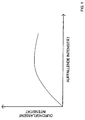
- a typical pass characteristic of such an OALSM is one linear relationship between lighting and transmitted intensity for low lighting intensities and a transition into one Saturation range in which the transmitted intensity is almost independent of the Lighting intensity is. For higher intensities, the transmitted one Intensity again depend more on the lighting intensity.
- the layers of the OASLM structured preferably in individual zones, in particular optical points (pixel) resolved, which can preferably be controlled individually.
- pixel optical points
- the layers of the OASLM structured, preferably in individual zones, in particular optical points (pixel) resolved, which can preferably be controlled individually.
- crosstalk between nearby pixels is reduced.
- additional pixels by electrical means into the modulator intervene, in particular the local transmission properties specifically to adapt to the initial intensity profile.
- the control of the Individual zones can be advantageously controlled by the shaped beam profile measured and for deviations from a target shape, in particular from the Rectangular shape, is examined.
- the size of the local deviations then serves via a feedback branch to adjust the transmission properties the zones or pixels of the OASLM.
- the intensity of the is too shaping laser beam preferably by expanding the beam and / or adapted to the saturation range of the OASLM using optical filters.
- to Beam expansion is preferably an imaging optics in the beam path inserted within which the OASLM is located.
- the imaging optics includes preferably two telescope imaging systems, which preferably as mechanically or electrically adjustable or adjustable zoom systems are.
- the beam expansion is variable, so that changes in intensity by Intensity fluctuations of the laser or after changing the laser can always be balanced.
- FIG. 1 schematically shows a typical transmission characteristic of a OASLM, as used according to the invention, the on the x-axis incident and the transmitted intensity is plotted on the y-axis.
- the OASLM exhibits an essentially linear one Transmission characteristic on, for example, it is for the incident radiation essentially transparent.
- this saturation area is used as the work area for beam shaping selected.
- the intensity of the incident laser beam to be shaped is determined by Filters or by beam expansion adapted to this work area. Beam expansion has the advantage that the light turns after passing through the OASLM can be bundled again and thus a lower loss of the overall intensity occurs.
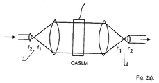
- FIGS. 2a-c show three arrangements for beam shaping according to the invention using an OASLM.
- FIG. 2a shows an arrangement in which the OASLM is inserted between two coupler telescopes 1, 2 in the beam path of a laser.
- the telescopes 1, 2 each consist of two lenses with focal lengths f 1 , f 2 and f 1 ', f 2 ', which are arranged at a distance f 1 + f 2 and f 1 '+ f 2 '.
- the telescopes are used for beam expansion in order to reduce the intensity in the center of the laser beam to such an extent that it falls within the plateau range of the characteristic according to FIG. 1.
- the laser beam with a flattened beam profile leaves the second telescope 2 on the right. If the beam is to be expanded at the same time, the right telescope 2 must have a lower magnification than the left telescope 1.
- intensity of the laser can already be optimally adapted to the OASLM.
- the Light can then be directed directly onto the OASLM without prior expansion as shown in Figure 2b.
- the light from fiber 3 falls directly on the Beamformer OASLM, which can be in optical contact with the fiber 3.
- reflection losses during the transition to the OASLM can be avoided keep it small by adjusting the refractive index with an oil.
- Advantage of this One embodiment is that the OASLM can be made particularly small.
- the invention can be used in a wide range of applications, in which it is based on the Illumination of surfaces with laser light is as uniform as possible, especially in image processing and projection technology, in the Interferometry, as well as in material processing using lasers, advantageous apply commercially.
Landscapes
- Physics & Mathematics (AREA)
- Nonlinear Science (AREA)
- Mathematical Physics (AREA)
- Chemical & Material Sciences (AREA)
- Crystallography & Structural Chemistry (AREA)
- General Physics & Mathematics (AREA)
- Optics & Photonics (AREA)
- Laser Beam Processing (AREA)
- Liquid Crystal (AREA)
- Lasers (AREA)
- Optical Modulation, Optical Deflection, Nonlinear Optics, Optical Demodulation, Optical Logic Elements (AREA)
Applications Claiming Priority (3)
| Application Number | Priority Date | Filing Date | Title |
|---|---|---|---|
| DE19931989A DE19931989A1 (de) | 1999-07-09 | 1999-07-09 | Verfahren und Vorrichtung zur Formung des Intensitätsprofils eines Laserstrahls |
| DE19931989 | 1999-07-09 | ||
| PCT/EP2000/005367 WO2001004685A1 (de) | 1999-07-09 | 2000-06-10 | Verfahren und vorrichtung zur formung des intensitätsprofils eines laserstrahls |
Publications (2)
| Publication Number | Publication Date |
|---|---|
| EP1116064A1 EP1116064A1 (de) | 2001-07-18 |
| EP1116064B1 true EP1116064B1 (de) | 2003-04-23 |
Family
ID=7914178
Family Applications (1)
| Application Number | Title | Priority Date | Filing Date |
|---|---|---|---|
| EP00942048A Expired - Lifetime EP1116064B1 (de) | 1999-07-09 | 2000-06-10 | Verfahren und vorrichtung zur formung des intensitätsprofils eines laserstrahls |
Country Status (6)
| Country | Link |
|---|---|
| US (1) | US6952296B1 (enExample) |
| EP (1) | EP1116064B1 (enExample) |
| JP (1) | JP4546684B2 (enExample) |
| AT (1) | ATE238571T1 (enExample) |
| DE (2) | DE19931989A1 (enExample) |
| WO (1) | WO2001004685A1 (enExample) |
Families Citing this family (7)
| Publication number | Priority date | Publication date | Assignee | Title |
|---|---|---|---|---|
| DE10231969B4 (de) * | 2002-07-15 | 2004-09-30 | Siemens Ag | Optisches Element zur Formung eines Lichtstrahls und Verfahren zum Bearbeiten von Objekten mittels Laserstrahlen |
| JP2004294756A (ja) * | 2003-03-27 | 2004-10-21 | Tdk Corp | 空間光変調器及びホログラム記録再生装置 |
| DE102004042670B4 (de) | 2003-09-02 | 2018-07-12 | CiS Forschungsinstitut für Mikrosensorik GmbH | Mikrooptisches Strahler- und Empfängersystem |
| US7253933B1 (en) | 2005-02-10 | 2007-08-07 | Hrl Laboratories, Llc | Apparatus and method for the temporal profiling of short laser pulses with thick Bragg gratings |
| US7088483B1 (en) | 2005-02-10 | 2006-08-08 | Hrl Laboratories, Llc | Holographic spatial laser beam shaper and method |
| US10012544B2 (en) * | 2016-11-29 | 2018-07-03 | Cymer, Llc | Homogenization of light beam for spectral feature metrology |
| DE102017203669B3 (de) | 2017-03-07 | 2018-06-28 | Robert Bosch Gmbh | Verfahren und Vorrichtung zur Formung kohärenter Strahlung |
Family Cites Families (11)
| Publication number | Priority date | Publication date | Assignee | Title |
|---|---|---|---|---|
| US4632518A (en) * | 1984-07-31 | 1986-12-30 | Hughes Aircraft Company | Phase insensitive optical logic gate device |
| US4926177A (en) * | 1987-05-21 | 1990-05-15 | Canon Kabushiki Kaisha | Optical analog-digital converter provided with a nonlinear optical element and an optical feedback system for the output lights of said element |
| US4953937A (en) * | 1988-05-17 | 1990-09-04 | Olympus Optical Co., Ltd. | Illumination optical system |
| JP2738724B2 (ja) * | 1988-11-25 | 1998-04-08 | 松下電器産業株式会社 | 空間光変調素子及び神経ネットワーク回路 |
| DE69026861T2 (de) * | 1989-03-23 | 1996-11-14 | Victor Company Of Japan | Element zur Lichtumwandlung und eine Abbildungsvorrichtung |
| US5073010A (en) * | 1990-05-11 | 1991-12-17 | University Of Colorado Foundation, Inc. | Optically addressable spatial light modulator having a distorted helix ferroelectric liquid crystal member |
| US5835469A (en) * | 1990-05-25 | 1998-11-10 | Hitachi, Ltd. | High-density information recording/reproducing method |
| US5528702A (en) * | 1991-05-31 | 1996-06-18 | Seiko Instruments Inc. | Optical pattern recognition apparatus with coordinate conversion function |
| US5610733A (en) * | 1994-02-28 | 1997-03-11 | Digital Optics Corporation | Beam-homogenizer |
| DE19616323A1 (de) * | 1996-04-24 | 1997-10-30 | Deutsche Telekom Ag | Vorrichtung zur lokalen Abschwächung der Lichtintensität |
| US5986807A (en) * | 1997-01-13 | 1999-11-16 | Xerox Corporation | Single binary optical element beam homogenizer |
-
1999
- 1999-07-09 DE DE19931989A patent/DE19931989A1/de not_active Withdrawn
-
2000
- 2000-06-10 US US09/786,837 patent/US6952296B1/en not_active Expired - Fee Related
- 2000-06-10 DE DE50001853T patent/DE50001853D1/de not_active Expired - Lifetime
- 2000-06-10 JP JP2001510036A patent/JP4546684B2/ja not_active Expired - Fee Related
- 2000-06-10 AT AT00942048T patent/ATE238571T1/de not_active IP Right Cessation
- 2000-06-10 EP EP00942048A patent/EP1116064B1/de not_active Expired - Lifetime
- 2000-06-10 WO PCT/EP2000/005367 patent/WO2001004685A1/de not_active Ceased
Also Published As
| Publication number | Publication date |
|---|---|
| WO2001004685A1 (de) | 2001-01-18 |
| JP2003504688A (ja) | 2003-02-04 |
| DE19931989A1 (de) | 2001-01-11 |
| JP4546684B2 (ja) | 2010-09-15 |
| US6952296B1 (en) | 2005-10-04 |
| EP1116064A1 (de) | 2001-07-18 |
| ATE238571T1 (de) | 2003-05-15 |
| DE50001853D1 (de) | 2003-05-28 |
Similar Documents
| Publication | Publication Date | Title |
|---|---|---|
| EP1066546B1 (de) | Verfahren und vorrichtung zur resonanzverstärkung, insbesondere zur abstimmbaren frequenzkonversion von laserstrahlung | |
| EP2556397B1 (de) | Verfahren und anordnung zum erzeugen eines laserstrahls mit unterschiedlicher strahlprofilcharakteristik mittels einer mehrfachclad-faser | |
| EP2901458B1 (de) | Strahlführungseinrichtung und verfahren zum einstellen des öffnungswinkels eines laserstrahls | |
| WO2007131810A1 (de) | Reflektierendes optisches system, nachführsystem sowie holografisches projektionssystem und -verfahren | |
| DE102012216284A1 (de) | Mikrolithographische Projektionsbelichtungsanlage | |
| EP2547486B1 (de) | Verfahren und vorrichtung zur räumlich periodischen modifikation einer substratoberfläche unter verwendung einer telezentrischen f-theta-optik | |
| EP3762176B1 (de) | Verfahren und vorrichtung zur bearbeitung mittels interferierender laserstrahlung | |
| DE102011113521A1 (de) | Mikrolithographische Projektionsbelichtungsanlage | |
| EP3955048B1 (de) | Anordnung zur erzeugung eines bessel-strahls | |
| DE10338472A1 (de) | Optisches Abbildungssystem mit erweiterter Schärfentiefe | |
| EP1116064B1 (de) | Verfahren und vorrichtung zur formung des intensitätsprofils eines laserstrahls | |
| WO2001036208A2 (de) | Verfahren zum aufbringen von farbigen informationen auf einen gegenstand | |
| DE102007039019A1 (de) | Vorrichtung zum Schwenken eines optischen Strahls | |
| DE102019201280A1 (de) | Anordnung und Verfahren zum Formen eines Laserstrahls | |
| WO2021074011A1 (de) | Wellenfrontmanipulator mit diffraktiven komponenten | |
| DE10007391A1 (de) | Verfahren und Vorrichtung für die Materialbearbeitung | |
| WO2020020782A1 (de) | Vorrichtung zur strahlformung für einen zur materialbearbeitung eingesetzten laserstrahl | |
| DE102004011190B4 (de) | Optischer Strahlformer mit einem Laser mit ultrakurzer Pulsdauer | |
| EP4263118A1 (de) | Vorrichtung zur strahlbeeinflussung eines laserstrahls | |
| EP2171515A1 (de) | Mikromechanische vorrichtung und verfahren zum projizieren elektromagnetischer strahlung | |
| WO2025114219A1 (de) | System zum replizieren eines objekts der holografie | |
| EP4621454A1 (de) | Verfahren zur kompensation der laufzeitunterschiede von bildwellenleitern | |
| DE102022211350A1 (de) | Laseranordnung und Verfahren zum Betrieb der Laseranordnung | |
| DE102010041739A1 (de) | Optisches System zur Behandlung eines in einer Bearbeitungsebene angeordneten Substrats | |
| WO2023227656A1 (de) | Strahl-aufweiter für eine replikationsanlage |
Legal Events
| Date | Code | Title | Description |
|---|---|---|---|
| PUAI | Public reference made under article 153(3) epc to a published international application that has entered the european phase |
Free format text: ORIGINAL CODE: 0009012 |
|
| AK | Designated contracting states |
Kind code of ref document: A1 Designated state(s): AT BE CH CY DE DK ES FI FR GB GR IE IT LI LU MC NL PT SE |
|
| 17P | Request for examination filed |
Effective date: 20010718 |
|
| GRAG | Despatch of communication of intention to grant |
Free format text: ORIGINAL CODE: EPIDOS AGRA |
|
| 17Q | First examination report despatched |
Effective date: 20020610 |
|
| GRAG | Despatch of communication of intention to grant |
Free format text: ORIGINAL CODE: EPIDOS AGRA |
|
| GRAH | Despatch of communication of intention to grant a patent |
Free format text: ORIGINAL CODE: EPIDOS IGRA |
|
| GRAH | Despatch of communication of intention to grant a patent |
Free format text: ORIGINAL CODE: EPIDOS IGRA |
|
| GRAA | (expected) grant |
Free format text: ORIGINAL CODE: 0009210 |
|
| AK | Designated contracting states |
Designated state(s): AT BE CH CY DE DK ES FI FR GB GR IE IT LI LU MC NL PT SE |
|
| PG25 | Lapsed in a contracting state [announced via postgrant information from national office to epo] |
Ref country code: FI Free format text: LAPSE BECAUSE OF FAILURE TO SUBMIT A TRANSLATION OF THE DESCRIPTION OR TO PAY THE FEE WITHIN THE PRESCRIBED TIME-LIMIT Effective date: 20030423 Ref country code: IE Free format text: LAPSE BECAUSE OF NON-PAYMENT OF DUE FEES Effective date: 20030423 Ref country code: NL Free format text: LAPSE BECAUSE OF FAILURE TO SUBMIT A TRANSLATION OF THE DESCRIPTION OR TO PAY THE FEE WITHIN THE PRESCRIBED TIME-LIMIT Effective date: 20030423 |
|
| REG | Reference to a national code |
Ref country code: GB Ref legal event code: FG4D Free format text: NOT ENGLISH |
|
| REG | Reference to a national code |
Ref country code: CH Ref legal event code: EP |
|
| REF | Corresponds to: |
Ref document number: 50001853 Country of ref document: DE Date of ref document: 20030528 Kind code of ref document: P |
|
| REG | Reference to a national code |
Ref country code: IE Ref legal event code: FG4D Free format text: GERMAN |
|
| PG25 | Lapsed in a contracting state [announced via postgrant information from national office to epo] |
Ref country code: CY Free format text: LAPSE BECAUSE OF FAILURE TO SUBMIT A TRANSLATION OF THE DESCRIPTION OR TO PAY THE FEE WITHIN THE PRESCRIBED TIME-LIMIT Effective date: 20030610 Ref country code: AT Free format text: LAPSE BECAUSE OF NON-PAYMENT OF DUE FEES Effective date: 20030610 Ref country code: LU Free format text: LAPSE BECAUSE OF NON-PAYMENT OF DUE FEES Effective date: 20030610 |
|
| PG25 | Lapsed in a contracting state [announced via postgrant information from national office to epo] |
Ref country code: MC Free format text: LAPSE BECAUSE OF NON-PAYMENT OF DUE FEES Effective date: 20030630 |
|
| PG25 | Lapsed in a contracting state [announced via postgrant information from national office to epo] |
Ref country code: DK Free format text: LAPSE BECAUSE OF FAILURE TO SUBMIT A TRANSLATION OF THE DESCRIPTION OR TO PAY THE FEE WITHIN THE PRESCRIBED TIME-LIMIT Effective date: 20030723 Ref country code: SE Free format text: LAPSE BECAUSE OF FAILURE TO SUBMIT A TRANSLATION OF THE DESCRIPTION OR TO PAY THE FEE WITHIN THE PRESCRIBED TIME-LIMIT Effective date: 20030723 Ref country code: PT Free format text: LAPSE BECAUSE OF FAILURE TO SUBMIT A TRANSLATION OF THE DESCRIPTION OR TO PAY THE FEE WITHIN THE PRESCRIBED TIME-LIMIT Effective date: 20030723 Ref country code: GR Free format text: LAPSE BECAUSE OF FAILURE TO SUBMIT A TRANSLATION OF THE DESCRIPTION OR TO PAY THE FEE WITHIN THE PRESCRIBED TIME-LIMIT Effective date: 20030723 |
|
| GBT | Gb: translation of ep patent filed (gb section 77(6)(a)/1977) | ||
| NLV1 | Nl: lapsed or annulled due to failure to fulfill the requirements of art. 29p and 29m of the patents act | ||
| PG25 | Lapsed in a contracting state [announced via postgrant information from national office to epo] |
Ref country code: ES Free format text: LAPSE BECAUSE OF FAILURE TO SUBMIT A TRANSLATION OF THE DESCRIPTION OR TO PAY THE FEE WITHIN THE PRESCRIBED TIME-LIMIT Effective date: 20031030 |
|
| REG | Reference to a national code |
Ref country code: IE Ref legal event code: FD4D Ref document number: 1116064E Country of ref document: IE |
|
| BERE | Be: lapsed |
Owner name: DEUTSCHE *TELEKOM A.G. Effective date: 20030630 |
|
| ET | Fr: translation filed | ||
| PLBE | No opposition filed within time limit |
Free format text: ORIGINAL CODE: 0009261 |
|
| STAA | Information on the status of an ep patent application or granted ep patent |
Free format text: STATUS: NO OPPOSITION FILED WITHIN TIME LIMIT |
|
| 26N | No opposition filed |
Effective date: 20040126 |
|
| PG25 | Lapsed in a contracting state [announced via postgrant information from national office to epo] |
Ref country code: CH Free format text: LAPSE BECAUSE OF NON-PAYMENT OF DUE FEES Effective date: 20040630 Ref country code: LI Free format text: LAPSE BECAUSE OF NON-PAYMENT OF DUE FEES Effective date: 20040630 |
|
| REG | Reference to a national code |
Ref country code: CH Ref legal event code: PL |
|
| PG25 | Lapsed in a contracting state [announced via postgrant information from national office to epo] |
Ref country code: BE Free format text: LAPSE BECAUSE OF NON-PAYMENT OF DUE FEES Effective date: 20030630 |
|
| PGFP | Annual fee paid to national office [announced via postgrant information from national office to epo] |
Ref country code: FR Payment date: 20100706 Year of fee payment: 11 |
|
| PGFP | Annual fee paid to national office [announced via postgrant information from national office to epo] |
Ref country code: IT Payment date: 20100626 Year of fee payment: 11 |
|
| PGFP | Annual fee paid to national office [announced via postgrant information from national office to epo] |
Ref country code: DE Payment date: 20100825 Year of fee payment: 11 Ref country code: GB Payment date: 20100623 Year of fee payment: 11 |
|
| GBPC | Gb: european patent ceased through non-payment of renewal fee |
Effective date: 20110610 |
|
| PG25 | Lapsed in a contracting state [announced via postgrant information from national office to epo] |
Ref country code: IT Free format text: LAPSE BECAUSE OF NON-PAYMENT OF DUE FEES Effective date: 20110610 |
|
| REG | Reference to a national code |
Ref country code: FR Ref legal event code: ST Effective date: 20120229 |
|
| REG | Reference to a national code |
Ref country code: DE Ref legal event code: R119 Ref document number: 50001853 Country of ref document: DE Effective date: 20120103 |
|
| PG25 | Lapsed in a contracting state [announced via postgrant information from national office to epo] |
Ref country code: FR Free format text: LAPSE BECAUSE OF NON-PAYMENT OF DUE FEES Effective date: 20110630 Ref country code: DE Free format text: LAPSE BECAUSE OF NON-PAYMENT OF DUE FEES Effective date: 20120103 |
|
| PG25 | Lapsed in a contracting state [announced via postgrant information from national office to epo] |
Ref country code: GB Free format text: LAPSE BECAUSE OF NON-PAYMENT OF DUE FEES Effective date: 20110610 |