EP1115067A2 - Bussystemtreiber - Google Patents
Bussystemtreiber Download PDFInfo
- Publication number
- EP1115067A2 EP1115067A2 EP00126008A EP00126008A EP1115067A2 EP 1115067 A2 EP1115067 A2 EP 1115067A2 EP 00126008 A EP00126008 A EP 00126008A EP 00126008 A EP00126008 A EP 00126008A EP 1115067 A2 EP1115067 A2 EP 1115067A2
- Authority
- EP
- European Patent Office
- Prior art keywords
- bus
- bus system
- interruption
- drivers
- points
- Prior art date
- Legal status (The legal status is an assumption and is not a legal conclusion. Google has not performed a legal analysis and makes no representation as to the accuracy of the status listed.)
- Ceased
Links
Images
Classifications
-
- G—PHYSICS
- G06—COMPUTING OR CALCULATING; COUNTING
- G06F—ELECTRIC DIGITAL DATA PROCESSING
- G06F13/00—Interconnection of, or transfer of information or other signals between, memories, input/output devices or central processing units
- G06F13/38—Information transfer, e.g. on bus
- G06F13/40—Bus structure
- G06F13/4004—Coupling between buses
- G06F13/4022—Coupling between buses using switching circuits, e.g. switching matrix, connection or expansion network
Definitions
- the present invention relates to a bus system with a an output leading bus and a large number of wiring harnesses, each via a driver (control element) Connection points are connected to the bus.
- buses can be tristate buses, for example, buses that are able to assume three states, namely "driven high” high), “driven low” and “not driven ".
- the individual wiring harnesses are located in front of the connection points by bus the drivers that are a reinforcement of the signals in the individual lines of the respective line strings cause and the wiring harness or the line Select the one that is currently connecting to the bus can.
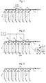
- FIG. 3 schematically shows such an existing bus system with a bus 1, which leads to an output DOUT and to which a wiring harness 3 0 to 3 7 is connected at connection points 2.
- a driver 4 which can be controlled via a control connection 5 in order to select that wiring harness from the wiring harnesses 3 0 to 3 7 that is to be connected to the bus 1, and in the selected one To amplify wiring routed signal.
- the line strands 3 0 to 3 7 can each be one line or else several lines, for example eight lines. If there are several lines in a line section 3 0 to 3 7 , the driver 4 can additionally pick out a line from the selected line section and connect this line to the bus 1.
- bus system shown in FIG. 3 works excellently as long as the number of drivers 4 is relatively small.
- the operating behavior of the bus system deteriorates, however, the more drivers 4 with wiring harnesses 3 0 to 3 7 and control lines 5 for enable signals are connected to bus 1.
- Each driver 4 is namely influenced in its operating behavior by the capacities of the other drivers 4. In other words, each individual driver 4 also "sees" the other drivers 4.
- This task is performed in a bus system of the type mentioned at the beginning Art solved according to the invention in that the bus between at least two connection points an optional interruption point having.
- the bus in the bus system according to the invention can easily be used between two connection points, depending on requirements be interrupted, which means that all Driver that is in the signal direction before the break point lie, no longer contribute to the capacity of the bus system. That is, in the bus system according to the invention all drivers "before" the point of interruption from excluded from consideration, resulting in a significant reduction the capacity, which in turn is enabled the reduction in the operating speed of the bus system significantly reduced.
- the bus can without in the bus system according to the invention another between two junctions between the bus and the wiring harnesses are interrupted.
- An optional interruption point can, for example can be created in that the bus 1 (see initially Fig. 3) is designed between two connection points 2, that he easily between these two junctions is interruptible. This can be done, for example, by action a corresponding laser beam, by etching or done by other removal.
- at the bus system according to the invention can be arranged by the optionally Interruption point to be ensured that Drivers not required when generating the output signal DOUT (see Fig. 3) contribute to long-term operation to ensure the bus system.
- Fig. 1 shows an embodiment in which of the wiring harnesses 3 0 to 3 7 , which here can consist of eight lines, for example, the wiring harnesses 3 0 to 3 3 with their associated drivers 4 do not impair the capacity of the bus 2 at its DOUT output , since the bus 2 between the connection points 2 of the wiring harnesses 3 3 and 3 4 is interrupted.
- the interruption was chosen at this point because only the wiring harnesses 3 4 to 3 7 with their associated drivers 4 are required in the present case. In other words, in the case of the invention, interruption points of the bus 1 are provided where a disconnection of unnecessary cable runs can be expected.
- interruption points can be designed so that they represent "breaking points" for bus 1 at which this can be separated electrically very easily. For example, it is possible to determine bus 1 for this purpose To design places where there are interruptions, that it is easily exposed to a laser beam is to be melted. Of course, are other interruption options for bus 1 are also conceivable, such as an interruption due to local exposure an etchant.
- Fig. 2 shows a further embodiment of the invention, in which potential interruption points between the connection points 2 of the wiring harnesses 3 1 and 3 2 , the wiring harnesses 3 3 and 3 4 and the wiring harnesses 3 5 and 3 6 are provided.
- the bus can be separated at the specified interruption points. It is therefore possible to connect only the wiring harnesses 3 6 and 3 7 or only the wiring harnesses 3 4 to 3 7 or only the wiring harnesses 3 2 to 3 7 with their associated drivers 4 to the DOUT output of the bus 1 by using the specified ones Interruption points a separation is made.
- all wiring harnesses 3 0 to 3 7 can also remain connected to the DOUT output by not separating them at the interruption points.
- ground potential GND can be applied to the control lines 5 for the drivers 4 of the wiring harnesses 3 0 to 3 5 , as shown in FIG 2 is shown.
- the buses 1 can be reduced to one line. As well it is also possible that several buses 1 each from individual Lines 8 exist in which the programmable units 6 installed as interruption points in different positions are, as illustrated in detail A of FIG. 2 is.
- the invention thus creates the possibility, in a simple manner, of connecting only those line strands 3 0 to 3 7 to a bus 1 which are actually required. Burning off or disconnecting the other wiring harnesses ensures that a low-capacity bus system is present, the operating speed of which is affected as little as possible by the capacities of the remaining wiring harnesses and drivers 4.
Landscapes
- Engineering & Computer Science (AREA)
- Physics & Mathematics (AREA)
- General Engineering & Computer Science (AREA)
- Theoretical Computer Science (AREA)
- Mathematical Physics (AREA)
- Computer Hardware Design (AREA)
- General Physics & Mathematics (AREA)
- Bus Control (AREA)
- Small-Scale Networks (AREA)
- Semiconductor Integrated Circuits (AREA)
- Logic Circuits (AREA)
Abstract
Description
- Fig. 1
- eine schematische Darstellung eines ersten Ausführungsbeispiels der Erfindung,
- Fig. 2
- eine schematische Darstellung eines weiteren Ausführungsbeispiels der Erfindung und
- Fig. 3
- ein bestehendes Bussystem.
Claims (8)
- Bussystem mit einem zu einem Ausgang (DOUT) führenden Busdadurch gekennzeichnet, daß der Bus (1) zwischen wenigstens zwei Verbindungsstellen (2) eine wahlweise Unterbrechungsstelle aufweist.(1) und einer Vielzahl von Leitungssträngen (31 bis 37), die über jeweils einen Driver (4) an Verbindungsstellen(2) mit dem Bus (1) verbunden sind,
- Bussystem nach Anspruch 1,
dadurch gekennzeichnet, daß die wahlweise Unterbrechungsstelle bei Bedarf eine Unterbrechung des Busses (1) erlaubt. - Bussystem nach Anspruch 1 oder 2,
dadurch gekennzeichnet, daß die Unterbrechungsstellen in regelmäßigen Intervallen längs des Busses (1) vorgesehen sind. - Bussystem nach einem der Ansprüche 1 bis 3,
dadurch gekennzeichnet, daß der Bus ein Tristate-Bus (1) ist. - Bussystem nach einem der Ansprüche 1 bis 4,
dadurch gekennzeichnet, daß jeder Leitungsstrang (30 bis 37) mehrere Leitungen aufweist. - Bussystem nach einem der Ansprüche 1 bis 5,
dadurch gekennzeichnet, daß der Bus (1) zu einer Leitung reduziert ist. - Bussystem nach einem der Ansprüche 1 bis 6,
dadurch gekennzeichnet, daß mehrere Busse jeweils aus einzelnen Leitungen bestehen, die hinsichtlich Lage der Unterbrechungsstellen in den Leitungen der einzelnen Busse (1) und der Anzahl der Leitungen in den Bussen (1) unterschiedlich sind. - Bussystem nach einem der Ansprüche 1 bis 7,
dadurch gekennzeichnet, daß die Unterbrechungsstellen jeweils durch eine programmierbare Einheit mit den Zuständen "Unterbrechen" und "Verbinden" realisiert sind.
Applications Claiming Priority (2)
| Application Number | Priority Date | Filing Date | Title |
|---|---|---|---|
| DE19960243A DE19960243A1 (de) | 1999-12-14 | 1999-12-14 | Bussystem |
| DE19960243 | 1999-12-14 |
Publications (2)
| Publication Number | Publication Date |
|---|---|
| EP1115067A2 true EP1115067A2 (de) | 2001-07-11 |
| EP1115067A3 EP1115067A3 (de) | 2004-01-28 |
Family
ID=7932604
Family Applications (1)
| Application Number | Title | Priority Date | Filing Date |
|---|---|---|---|
| EP00126008A Ceased EP1115067A3 (de) | 1999-12-14 | 2000-11-28 | Bussystemtreiber |
Country Status (6)
| Country | Link |
|---|---|
| US (1) | US6715012B2 (de) |
| EP (1) | EP1115067A3 (de) |
| JP (1) | JP2001236152A (de) |
| KR (1) | KR20010062425A (de) |
| DE (1) | DE19960243A1 (de) |
| TW (1) | TW522696B (de) |
Cited By (2)
| Publication number | Priority date | Publication date | Assignee | Title |
|---|---|---|---|---|
| EP2525386A1 (de) | 2011-05-16 | 2012-11-21 | FEI Company | Mikroskopie mit geladenen Teilchen mit Okklusionsdetektion |
| EP2544025A1 (de) | 2011-07-07 | 2013-01-09 | FEI Company | Siliziumdriftdetektor zur Verwendung in einer Vorrichtung für geladene Teilchen |
Families Citing this family (3)
| Publication number | Priority date | Publication date | Assignee | Title |
|---|---|---|---|---|
| US7039734B2 (en) * | 2002-09-24 | 2006-05-02 | Hewlett-Packard Development Company, L.P. | System and method of mastering a serial bus |
| AU2003295277A1 (en) * | 2003-12-24 | 2005-07-14 | Telefonaktiebolaget Lm Ericsson (Publ) | Multisectional bus in radio base station and method of using such a radio base station |
| US10002243B1 (en) * | 2017-03-24 | 2018-06-19 | Wipro Limited | System and method for powering on electronic devices |
Family Cites Families (13)
| Publication number | Priority date | Publication date | Assignee | Title |
|---|---|---|---|---|
| JP3628847B2 (ja) * | 1997-08-18 | 2005-03-16 | 株式会社日立製作所 | バス切り換え装置、コンピュータ、および情報処理装置 |
| US4658333A (en) * | 1985-11-08 | 1987-04-14 | At&T Information Systems Inc. | Variable length backplane bus |
| FR2605768B1 (fr) * | 1986-10-23 | 1989-05-05 | Bull Sa | Dispositif de commande de bus constitue par plusieurs segments isolables |
| JPH0926841A (ja) * | 1995-07-10 | 1997-01-28 | Toshiba Corp | データ転送回路 |
| US5649126A (en) * | 1995-12-04 | 1997-07-15 | Sun Microsystems, Inc. | Parallel signal bus with reduced miller effect capacitance |
| US5677638A (en) * | 1996-02-02 | 1997-10-14 | Xilinx, Inc. | High speed tristate bus with multiplexers for selecting bus driver |
| US5887144A (en) * | 1996-11-20 | 1999-03-23 | International Business Machines Corp. | Method and system for increasing the load and expansion capabilities of a bus through the use of in-line switches |
| EP0892352B1 (de) * | 1997-07-18 | 2005-04-13 | Bull S.A. | Rechnersystem mit einem geteilten strukturierten Bus |
| US6081863A (en) * | 1998-03-13 | 2000-06-27 | International Business Machines Corporation | Method and system for supporting multiple peripheral component interconnect PCI buses by a single PCI host bridge within a computer system |
| US6295568B1 (en) * | 1998-04-06 | 2001-09-25 | International Business Machines Corporation | Method and system for supporting multiple local buses operating at different frequencies |
| US6035355A (en) * | 1998-04-27 | 2000-03-07 | International Business Machines Corporation | PCI system and adapter requirements following reset |
| US6182178B1 (en) * | 1998-06-30 | 2001-01-30 | International Business Machines Corporation | Method and system for supporting peripheral component interconnect (PCI) peer-to-peer access across a PCI host bridge supporting multiple PCI buses |
| US6338107B1 (en) * | 1998-12-16 | 2002-01-08 | International Business Machines Corporation | Method and system for providing hot plug of adapter cards in an expanded slot environment |
-
1999
- 1999-12-14 DE DE19960243A patent/DE19960243A1/de not_active Withdrawn
-
2000
- 2000-11-28 EP EP00126008A patent/EP1115067A3/de not_active Ceased
- 2000-12-11 JP JP2000376440A patent/JP2001236152A/ja not_active Withdrawn
- 2000-12-13 TW TW089126566A patent/TW522696B/zh not_active IP Right Cessation
- 2000-12-14 KR KR1020000076405A patent/KR20010062425A/ko not_active Ceased
- 2000-12-14 US US09/737,060 patent/US6715012B2/en not_active Expired - Lifetime
Non-Patent Citations (1)
| Title |
|---|
| 1988, COMPUTER ARCHITECTURE AND ORGANIZATION, J.P. HAYES, 1988, MCGRAW-HILL BOOK COMPANY, SINGAPORE * |
Cited By (3)
| Publication number | Priority date | Publication date | Assignee | Title |
|---|---|---|---|---|
| EP2525386A1 (de) | 2011-05-16 | 2012-11-21 | FEI Company | Mikroskopie mit geladenen Teilchen mit Okklusionsdetektion |
| EP2544025A1 (de) | 2011-07-07 | 2013-01-09 | FEI Company | Siliziumdriftdetektor zur Verwendung in einer Vorrichtung für geladene Teilchen |
| EP2544026A1 (de) | 2011-07-07 | 2013-01-09 | Fei Company | Siliziumdriftdetektor zur Verwendung in einer Vorrichtung für geladene Teilchen |
Also Published As
| Publication number | Publication date |
|---|---|
| EP1115067A3 (de) | 2004-01-28 |
| US20010004748A1 (en) | 2001-06-21 |
| US6715012B2 (en) | 2004-03-30 |
| TW522696B (en) | 2003-03-01 |
| DE19960243A1 (de) | 2001-07-05 |
| JP2001236152A (ja) | 2001-08-31 |
| KR20010062425A (ko) | 2001-07-07 |
Similar Documents
| Publication | Publication Date | Title |
|---|---|---|
| EP0956220B1 (de) | Schalteranordnung für elektrische steuergeräte | |
| EP0417480B1 (de) | Verkabelungssystem für Fahrzeuge | |
| DE102015108372A1 (de) | Elektrischeversorgungseinrichtung und damit ausgestattetes bordnetz eines fahrzeugs | |
| DE19706798B4 (de) | Halbleiter-Leistungsmodul | |
| EP0222030B1 (de) | Initiatorklemmenblock | |
| DE19922408B4 (de) | Bus-System mit bei Störungen automatisch abschaltbaren Teilnetzen | |
| EP1115067A2 (de) | Bussystemtreiber | |
| DE10251763B3 (de) | Vorrichtung zur Ansteuerung mehrerer Elektromotoren | |
| DE102012003023A1 (de) | Energieversorgungseinheit zur Energieversorgung eines Fahrzeugs | |
| DE102021202496A1 (de) | Verteilungssystem für ein Bordnetz sowie Versorgungsstrang für ein solches Verteilungssystem | |
| DE102005039104A1 (de) | Bordnetz eines Hybridfahrzeugs mit sicherheitskritischen Verbrauchern | |
| AT521031B1 (de) | System für ein Doppellenker-Kraftfahrzeug | |
| EP0274639A1 (de) | Schutzschaltsystem | |
| DE202022105775U1 (de) | Modulare elektronische Sicherungen und Sicherungsbox | |
| DE602005001887T2 (de) | Querverbindung durch Permutationen mittels konfigurierbarer Leiterplatten | |
| EP1236306B1 (de) | Bussystem | |
| DE19725825C2 (de) | Neutralpunktgeklemmter Leistungsumrichter | |
| WO2015106979A1 (de) | Hochspannungsgleichstrom-übertragungssystem mit erdungsschalter | |
| DE19639252C1 (de) | Frei konfigurierbares Halbleiter-Treiberschaltungselement zur Ansteuerung elektrischer Lasten | |
| DE19733019C2 (de) | Elektrische Schaltungsanordnung | |
| EP3686056A1 (de) | Verkabelung und ansteuerungsmodul für ein anhängefahrzeug | |
| DE3437042C2 (de) | ||
| DE10236304A1 (de) | Schaltungsanordnung zur Ansteuerung und Überwachung elektrischer Beleuchtungseinrichtungen in Anhängefahrzeugen | |
| EP3544055B1 (de) | Elektrische schaltvorrichtung sowie verfahren zur herstellung einer elektrischen schaltvorrichtung | |
| EP0525532B1 (de) | Leitungsführung zum Anschliessen von Elektromotoren einer Krananlage, insbesondere einer Container-Krananlage |
Legal Events
| Date | Code | Title | Description |
|---|---|---|---|
| PUAI | Public reference made under article 153(3) epc to a published international application that has entered the european phase |
Free format text: ORIGINAL CODE: 0009012 |
|
| AK | Designated contracting states |
Kind code of ref document: A2 Designated state(s): AT BE CH CY DE DK ES FI FR GB GR IE IT LI LU MC NL PT SE TR |
|
| AX | Request for extension of the european patent |
Free format text: AL;LT;LV;MK;RO;SI |
|
| PUAL | Search report despatched |
Free format text: ORIGINAL CODE: 0009013 |
|
| AK | Designated contracting states |
Kind code of ref document: A3 Designated state(s): AT BE CH CY DE DK ES FI FR GB GR IE IT LI LU MC NL PT SE TR |
|
| AX | Request for extension of the european patent |
Extension state: AL LT LV MK RO SI |
|
| 17P | Request for examination filed |
Effective date: 20040708 |
|
| AKX | Designation fees paid |
Designated state(s): DE GB IE |
|
| 17Q | First examination report despatched |
Effective date: 20040915 |
|
| STAA | Information on the status of an ep patent application or granted ep patent |
Free format text: STATUS: THE APPLICATION HAS BEEN REFUSED |
|
| 18R | Application refused |
Effective date: 20050715 |