EP1114774A2 - Bordlageregelungssystem mit Reaktionsrädern - Google Patents
Bordlageregelungssystem mit Reaktionsrädern Download PDFInfo
- Publication number
- EP1114774A2 EP1114774A2 EP00311287A EP00311287A EP1114774A2 EP 1114774 A2 EP1114774 A2 EP 1114774A2 EP 00311287 A EP00311287 A EP 00311287A EP 00311287 A EP00311287 A EP 00311287A EP 1114774 A2 EP1114774 A2 EP 1114774A2
- Authority
- EP
- European Patent Office
- Prior art keywords
- attitude
- satellite
- axis
- data
- mission
- Prior art date
- Legal status (The legal status is an assumption and is not a legal conclusion. Google has not performed a legal analysis and makes no representation as to the accuracy of the status listed.)
- Withdrawn
Links
- 238000000034 method Methods 0.000 claims description 7
- 230000009466 transformation Effects 0.000 claims description 4
- 230000001131 transforming effect Effects 0.000 claims description 4
- 238000004364 calculation method Methods 0.000 description 3
- 238000004891 communication Methods 0.000 description 2
- 238000012937 correction Methods 0.000 description 2
- 238000010586 diagram Methods 0.000 description 2
- 230000033001 locomotion Effects 0.000 description 2
- 230000007246 mechanism Effects 0.000 description 2
- 238000012544 monitoring process Methods 0.000 description 2
- 230000003213 activating effect Effects 0.000 description 1
- 238000001514 detection method Methods 0.000 description 1
- 239000000446 fuel Substances 0.000 description 1
- 230000003252 repetitive effect Effects 0.000 description 1
- 239000013589 supplement Substances 0.000 description 1
- 238000012546 transfer Methods 0.000 description 1
Images

Classifications
-
- B—PERFORMING OPERATIONS; TRANSPORTING
- B64—AIRCRAFT; AVIATION; COSMONAUTICS
- B64G—COSMONAUTICS; VEHICLES OR EQUIPMENT THEREFOR
- B64G1/00—Cosmonautic vehicles
- B64G1/22—Parts of, or equipment specially adapted for fitting in or to, cosmonautic vehicles
- B64G1/24—Guiding or controlling apparatus, e.g. for attitude control
- B64G1/28—Guiding or controlling apparatus, e.g. for attitude control using inertia or gyro effect
- B64G1/285—Guiding or controlling apparatus, e.g. for attitude control using inertia or gyro effect using momentum wheels
-
- B—PERFORMING OPERATIONS; TRANSPORTING
- B64—AIRCRAFT; AVIATION; COSMONAUTICS
- B64G—COSMONAUTICS; VEHICLES OR EQUIPMENT THEREFOR
- B64G1/00—Cosmonautic vehicles
- B64G1/22—Parts of, or equipment specially adapted for fitting in or to, cosmonautic vehicles
- B64G1/24—Guiding or controlling apparatus, e.g. for attitude control
- B64G1/244—Spacecraft control systems
-
- B—PERFORMING OPERATIONS; TRANSPORTING
- B64—AIRCRAFT; AVIATION; COSMONAUTICS
- B64G—COSMONAUTICS; VEHICLES OR EQUIPMENT THEREFOR
- B64G1/00—Cosmonautic vehicles
- B64G1/22—Parts of, or equipment specially adapted for fitting in or to, cosmonautic vehicles
- B64G1/24—Guiding or controlling apparatus, e.g. for attitude control
- B64G1/28—Guiding or controlling apparatus, e.g. for attitude control using inertia or gyro effect
- B64G1/283—Guiding or controlling apparatus, e.g. for attitude control using inertia or gyro effect using reaction wheels
-
- B—PERFORMING OPERATIONS; TRANSPORTING
- B64—AIRCRAFT; AVIATION; COSMONAUTICS
- B64G—COSMONAUTICS; VEHICLES OR EQUIPMENT THEREFOR
- B64G1/00—Cosmonautic vehicles
- B64G1/22—Parts of, or equipment specially adapted for fitting in or to, cosmonautic vehicles
- B64G1/24—Guiding or controlling apparatus, e.g. for attitude control
- B64G1/32—Guiding or controlling apparatus, e.g. for attitude control using earth's magnetic field
-
- B—PERFORMING OPERATIONS; TRANSPORTING
- B64—AIRCRAFT; AVIATION; COSMONAUTICS
- B64G—COSMONAUTICS; VEHICLES OR EQUIPMENT THEREFOR
- B64G1/00—Cosmonautic vehicles
- B64G1/22—Parts of, or equipment specially adapted for fitting in or to, cosmonautic vehicles
- B64G1/24—Guiding or controlling apparatus, e.g. for attitude control
- B64G1/36—Guiding or controlling apparatus, e.g. for attitude control using sensors, e.g. sun-sensors, horizon sensors
- B64G1/363—Guiding or controlling apparatus, e.g. for attitude control using sensors, e.g. sun-sensors, horizon sensors using sun sensors
-
- B—PERFORMING OPERATIONS; TRANSPORTING
- B64—AIRCRAFT; AVIATION; COSMONAUTICS
- B64G—COSMONAUTICS; VEHICLES OR EQUIPMENT THEREFOR
- B64G1/00—Cosmonautic vehicles
- B64G1/22—Parts of, or equipment specially adapted for fitting in or to, cosmonautic vehicles
- B64G1/24—Guiding or controlling apparatus, e.g. for attitude control
- B64G1/36—Guiding or controlling apparatus, e.g. for attitude control using sensors, e.g. sun-sensors, horizon sensors
- B64G1/365—Guiding or controlling apparatus, e.g. for attitude control using sensors, e.g. sun-sensors, horizon sensors using horizon or Earth sensors
-
- B—PERFORMING OPERATIONS; TRANSPORTING
- B64—AIRCRAFT; AVIATION; COSMONAUTICS
- B64G—COSMONAUTICS; VEHICLES OR EQUIPMENT THEREFOR
- B64G1/00—Cosmonautic vehicles
- B64G1/22—Parts of, or equipment specially adapted for fitting in or to, cosmonautic vehicles
- B64G1/24—Guiding or controlling apparatus, e.g. for attitude control
- B64G1/36—Guiding or controlling apparatus, e.g. for attitude control using sensors, e.g. sun-sensors, horizon sensors
- B64G1/369—Guiding or controlling apparatus, e.g. for attitude control using sensors, e.g. sun-sensors, horizon sensors using gyroscopes as attitude sensors
Definitions
- the system of this application is designed to control the attitude of a satellite. Satellites must be maintained in a predetermined orbit and attitude in order to accomplish the assigned mission which can be surveillance, photography, detection and many others. The orbit and attitude of the satellite must be periodically adjusted to compensate for disturbances which occur in space or for the purpose of changing the mission.
- spacecraft attitude is adjusted by activating actuators, such as, momentum wheels, magnetic torguers, or thrusters in response to an attitude correction signal.
- the attitude error may be sensed by reference to sensors monitoring the position of the sun, stars and earth relative to the satellite or by onboard inertial sensors such as gyroscopes.
- the attitude is adjusted to its mission orientation in which the system is pointed at its predetermined target and is maintained in this orientation during orbital flight.
- the satellite is subject to motions induced by external forces, on board mechanisms or other sources and the attitude control system must continuously monitor and adjust attitude. Attitude control is therefore of primary importance in order to point the satellite to accomplish its mission and to maintain that position with the required accuracy.
- a control system for maintaining the attitude of a satellite in alignment with its mission attitude comprising:
- the control system of this invention employs a configuration of four reaction wheels preferably arranged in a trihedral relation as the primary attitude adjustment mechanism.
- the primary attitude sensors consist of a three axis gyroscope system.
- the control module includes stored orbital and related sun ephemeris data and appropriate estimating algorithms.
- the attitude is estimated with reference to the output of the three axis gyroscope system. Compensation for errors relating to gyroscope drift are provided by reference to data from on board earth and star sensors. Utilizing this data, the control module provides an estimate of the actual attitude of the satellite.
- the estimated attitude is compared to the desired attitude to obtain an attitude adjustment in terms of the three axis reference system.
- Each of the components of the adjustment is transformed to obtain the four wheel torque rates required to accomplish the adjustment.
- the predicted three axis torque adjustments are fed back to the control module.
- a satellite including a control system therefore, said control system including a ground station computer and a satellite onboard computer, a method of correcting the attitude of the satellite utilizing a reaction wheel assembly having a reference axis, said wheel assembly including four wheels, each of said wheels being mounted for rotation on an axis, said axes arranged in a configuration, wherein at least three of said axis are oblique to said reference axis, said method comprising the steps of:
- the basic components of the satellite 1 are shown in Figure 1 and include mission sensors 2, ground control computer 3, attitude adjustment actuators 4, and onboard computer 5.
- Ground control computer 3 is in microwave communication with the satellite computer 5 and transmits the attitude data required to fulfill the mission for storage in computer 5.
- the mission sensors 2 may include cameras, telescopes, communications antennae and other similar devices.
- the attitude adjustment actuators 4 are shown schematically as thrusters, but may also include other types of actuators, such as thrusters, momentum wheels, or magnetic torquers.
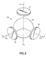
- a system of reaction wheels 18, as shown in figure 3 are used to supplement the thruster system.
- the thrusters 4 may be used for orbit transfer maneuvers, while the reaction wheel system 18 is used for smaller station keeping adjustments.
- the satellite 1 is oriented in space by reference to three axes orthogonal coordinates.
- the coordinate system includes an x axis which is generally tangent to the orbit path and referred to as the roll axis, a z axis which is generally pointed at the center of the earth and referred to as the yaw axis, and a y axis which is perpendicular to the other axes and referred to as the pitch axis.
- Pitch, yaw, and roll refer to rotational movement of the satellite about the particular axis.
- attitude control module 7 is constructed as part of the satellite control computer 5.
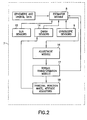
- a block diagram of the attitude control module 7 is shown in figure 2.
- the estimator module 8 contains modeling software which is capable of estimating the actual attitude of the satellite 1 from data sensed on board. Ephemeris and orbital data is up loaded and stored in the attitude control module 7 to allow the modeling software to take into consideration repetitive error causing disturbances.
- the primary source of sensed attitude data is a three axis gyroscope assembly 9. The data sensed by the gyroscopes are fed to the estimator module 8 and used to obtain an updated attitude for the satellite 1.
- the estimator module 8 uses least-square estimation techniques to combine the gyro data with the earth sensor data and sun sensor data to estimate both spacecraft attitude and gyro drift.
- the modeling software may be any of the available algorithms designed to calculate attitude from available data.
- the desired mission attitude is periodically up loaded from ground control computer 3 and stored in the attitude control module 7.
- the estimated actual attitude is compared to the mission attitude by the adjustment module 16 and an error calculation is obtained.
- This error calculation is converted to an attitude adjustment with components referencing the standard coordinate system.
- These data is converted by algorithms in the torque transformation module 17 to a four axis adjustment for actuating the four wheel actuator system 18. The latter transformation is accomplished as described in U.S. Patent No. 5,826,829, which issued on October 27, 1998, the contents of which are incorporated herein by reference.
- the trihedral momentum bias (TMB) wheel configuration of the invention uses four wheels of which any three can be used to provide the momentum bias and active nadir attitude three axis pointing.
- the four wheels are comprised of one momentum wheel and three reaction wheels.
- the three reaction wheels (typically smaller than the momentum wheel) are in a trihedral configuration which can provide the backup momentum bias should the momentum wheel fail. Full three-axis control would also be maintained if any one of the reaction wheels should fail.
- the wheel system can be operated in any of five modes: one using all four wheels and four modes each of which turn off one of the four wheels. It is up to the user which of five available wheel combinations will be used for nominal operation. If the three reaction wheels are used for nominal operations. and the reaction wheels are sized properly, it is possible to achieve three-axis active attitude control without any wheels being required to spin through zero rpm.
- the trihedral wheel system 18 includes a relatively large momentum wheel 10 mounted on the satellite, which wheel is rotatable about a spin axis (not shown) for maintaining gyroscopic stiffness of the spacecraft in space about a first axis.
- the wheel system 18 also includes a plurality of relatively smaller reaction wheels 11, 12, and 13 which, like the momentum wheel 10, are mounted on the spacecraft and rotatable on spin axes 111, 112, and 113, respectively, in a fixed, trihedral, configuration. Any two of the three reaction wheels 11-13, together with the momentum wheel 10, provide full three-axis control of the spacecraft in a predetermined attitude.
- the reaction wheels are flywheels with a vehicle-fixed axis designed to operate through zero wheel speed. In the event of a failure of the momentum wheel 10, the reaction wheels 11, 12, and 13 can be used to provide angular momentum sufficient to maintain the gyroscopic stiffness lost by the failure of the momentum wheel, while maintaining full three-axis control of the spacecraft in a predetermined attitude.
- the combined angular momentum of the remaining wheels is effective to maintain gyroscopic stiffness about the first axis while also maintaining full three-axis control of the spacecraft in a predetermined attitude.
- the momentum wheel 10 and the reaction wheels 11, 12, 13 are all rotatable about relatively fixed spin axes 111, 112, and 113 in a configuration for together maintaining gyroscopic stiffness and for maintaining three-axis control of the spacecraft. The details of this configuration are described in the above cited patent which is incorporated herein.
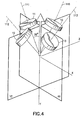
- FIG. 4 An alternative embodiment to the trihedral reaction wheel configuration, described above, is shown in figure 4.
- reaction wheels 10-13 are arranged with their spin axis 110 through 113 oblique to the y axis.
- the angle of each of the spin axes 110-113 is approximately 35°, but this could be virtually any angle depending on the amount of momentum bias needed for gyroscopic stiffness and the amount of momentum storage needed.
- Two of the spin axes are positioned in the yz plane and the other two spin axes are in the xy plane.
- the double V type of configuration also provides three axis control and three axis momentum storage by using any three of the four reaction wheels, while maintaining gyroscopic stiffness.
Landscapes
- Engineering & Computer Science (AREA)
- Remote Sensing (AREA)
- Chemical & Material Sciences (AREA)
- Combustion & Propulsion (AREA)
- Radar, Positioning & Navigation (AREA)
- Aviation & Aerospace Engineering (AREA)
- General Life Sciences & Earth Sciences (AREA)
- Life Sciences & Earth Sciences (AREA)
- Environmental & Geological Engineering (AREA)
- Geochemistry & Mineralogy (AREA)
- Geology (AREA)
- Automation & Control Theory (AREA)
- Control Of Position, Course, Altitude, Or Attitude Of Moving Bodies (AREA)
Applications Claiming Priority (2)
| Application Number | Priority Date | Filing Date | Title |
|---|---|---|---|
| US09/478,787 US6285928B1 (en) | 2000-01-06 | 2000-01-06 | Onboard attitude control using reaction wheels |
| US478787 | 2000-01-06 |
Publications (2)
| Publication Number | Publication Date |
|---|---|
| EP1114774A2 true EP1114774A2 (de) | 2001-07-11 |
| EP1114774A3 EP1114774A3 (de) | 2002-07-31 |
Family
ID=23901348
Family Applications (1)
| Application Number | Title | Priority Date | Filing Date |
|---|---|---|---|
| EP00311287A Withdrawn EP1114774A3 (de) | 2000-01-06 | 2000-12-15 | Bordlageregelungssystem mit Reaktionsrädern |
Country Status (3)
| Country | Link |
|---|---|
| US (1) | US6285928B1 (de) |
| EP (1) | EP1114774A3 (de) |
| JP (1) | JP2001240000A (de) |
Cited By (5)
| Publication number | Priority date | Publication date | Assignee | Title |
|---|---|---|---|---|
| CN106240846A (zh) * | 2015-06-15 | 2016-12-21 | 波音公司 | 交通工具姿态控制 |
| CN106774280A (zh) * | 2017-01-22 | 2017-05-31 | 上海航天控制技术研究所 | 一种反作用飞轮星上自主故障诊断方法 |
| EP3088981A4 (de) * | 2014-05-27 | 2017-09-13 | Beijing Aerospace Wanda Hi-Tech Ltd. | Nichtorthogonale six-rod-satellitenkommunikation in einem bewegungsservosystem und steuerverfahren |
| CN109444917A (zh) * | 2018-10-09 | 2019-03-08 | 中国人民解放军国防科技大学 | 基于微纳卫星集群的空间站外部结构检测维修系统及方法 |
| CN110329548A (zh) * | 2019-05-24 | 2019-10-15 | 中国人民解放军63789部队 | 航天器在轨转偏置控制下飞轮系统重构方法 |
Families Citing this family (27)
| Publication number | Priority date | Publication date | Assignee | Title |
|---|---|---|---|---|
| US6691955B2 (en) * | 2001-11-27 | 2004-02-17 | Space Systems/Loral | Spacecraft having a momentum wheel configuration that prevents zero wheel speeds |
| US6732977B1 (en) | 2002-02-11 | 2004-05-11 | Lockheed Martin Corporation | System for on-orbit correction of spacecraft payload pointing errors |
| US6695263B1 (en) | 2002-02-12 | 2004-02-24 | Lockheed Martin Corporation | System for geosynchronous spacecraft rapid earth reacquisition |
| US7051980B2 (en) * | 2002-02-26 | 2006-05-30 | Lockheed Martin Corporation | Efficient orbit sparing system for space vehicle constellations |
| US6702234B1 (en) | 2002-03-29 | 2004-03-09 | Lockheed Martin Corporation | Fault tolerant attitude control system for zero momentum spacecraft |
| US6600976B1 (en) * | 2002-03-29 | 2003-07-29 | Lockheed Martin Corporation | Gyroless control system for zero-momentum three-axis stabilized spacecraft |
| WO2004007287A2 (en) * | 2002-07-16 | 2004-01-22 | The Charles Stark Draper Laboratory, Inc. | Integrated inertial stellar attitude sensor |
| US7835826B1 (en) | 2005-12-13 | 2010-11-16 | Lockheed Martin Corporation | Attitude determination system for yaw-steering spacecraft |
| KR100932156B1 (ko) * | 2007-12-24 | 2009-12-16 | 한국항공우주연구원 | 영공간 벡터를 이용한 반작용휠 모멘텀 분배 방법 |
| JP4697254B2 (ja) * | 2008-04-02 | 2011-06-08 | トヨタ自動車株式会社 | 車両挙動制御装置 |
| US8209065B2 (en) * | 2009-01-21 | 2012-06-26 | The Boeing Company | Steering logic for spacecraft slew maneuvers |
| US8321076B2 (en) * | 2009-12-18 | 2012-11-27 | The Boeing Company | On-line inertia estimation for use in controlling an aerospace vehicle |
| US8763957B1 (en) * | 2012-10-08 | 2014-07-01 | Space Systems/Loral, Llc | Spacecraft transfer orbit techniques |
| US9073648B2 (en) * | 2013-02-15 | 2015-07-07 | The Boeing Company | Star tracker rate estimation with kalman filter enhancement |
| JP2015074382A (ja) * | 2013-10-10 | 2015-04-20 | 三菱重工業株式会社 | 姿勢検知装置、姿勢検知方法、及び姿勢検知プログラム |
| US10533856B2 (en) * | 2017-04-05 | 2020-01-14 | Novatel Inc. | Navigation system utilizing yaw rate constraint during inertial dead reckoning |
| CN108791955B (zh) * | 2018-06-14 | 2020-03-06 | 上海卫星工程研究所 | 静止遥感卫星相机太阳规避方法 |
| CN112758359A (zh) * | 2021-01-20 | 2021-05-07 | 北京国电高科科技有限公司 | 一种偏置动量卫星的区域覆盖控制方法 |
| WO2022197797A1 (en) | 2021-03-16 | 2022-09-22 | Ast & Science Llc | Momentum wheels and reaction wheels for objects in space |
| CN112896556B (zh) * | 2021-03-23 | 2024-07-19 | 湖南揽月机电科技有限公司 | 一种阵列式卫星智能姿控组件及其工作方法 |
| CN112937920B (zh) * | 2021-03-30 | 2024-07-19 | 湖南揽月机电科技有限公司 | 一种多冗余卫星智能姿控组件及其工作方法 |
| CN114756039B (zh) * | 2022-04-13 | 2025-08-05 | 椭圆时空(北京)科技有限公司 | 基于零力控制的多体耦合姿态控制方法与系统 |
| CN115339653B (zh) * | 2022-07-01 | 2024-11-08 | 上海卫星工程研究所 | 卫星慢旋姿态下停旋保测控时机预报方法及系统 |
| CN115848647B (zh) * | 2022-08-10 | 2023-06-27 | 北京星河动力装备科技有限公司 | 固体运载火箭及其留轨末子级 |
| CN116038700B (zh) * | 2022-12-30 | 2025-09-26 | 杭州程天科技发展有限公司 | 一种三轴动量轮自平衡机器人的控制方法、控制系统及存储介质 |
| CN117302556A (zh) * | 2023-09-28 | 2023-12-29 | 西北工业大学 | 一种频繁偏航机动工况下卫星飞轮控制方法及系统 |
| DE102023136422B3 (de) * | 2023-12-21 | 2025-06-18 | Deutsches Zentrum für Luft- und Raumfahrt e.V. | Weltraumhandhabungsvorrichtung |
Citations (1)
| Publication number | Priority date | Publication date | Assignee | Title |
|---|---|---|---|---|
| US5826829A (en) | 1996-07-15 | 1998-10-27 | Space Systems/Loral Inc. | Spacecraft control system with a trihedral momentum bias wheel configuration |
Family Cites Families (16)
| Publication number | Priority date | Publication date | Assignee | Title |
|---|---|---|---|---|
| US3999729A (en) | 1975-03-20 | 1976-12-28 | Rca Corporation | Backup wheel for a three axis reaction wheel spacecraft |
| US4071211A (en) * | 1976-09-23 | 1978-01-31 | Rca Corporation | Momentum biased active three-axis satellite attitude control system |
| FR2637565B1 (fr) | 1988-10-06 | 1991-01-11 | Aerospatiale | Systeme de controle actif selon trois axes de l'attitude d'un satellite geostationnaire |
| US5020745A (en) | 1989-12-20 | 1991-06-04 | General Electric Company | Reaction wheel fricton compensation using dither |
| US5098041A (en) * | 1990-06-07 | 1992-03-24 | Hughes Aircraft Company | Attitude control system for momentum-biased spacecraft |
| US5058835A (en) | 1990-06-11 | 1991-10-22 | General Electric Company | Wheel speed management control system for spacecraft |
| US5130931A (en) | 1990-07-13 | 1992-07-14 | General Electric Company | Spacecraft attitude and velocity control system |
| FR2670746B1 (fr) * | 1990-12-21 | 1993-04-16 | Aerospatiale | Systeme de controle d'attitude pour satellite 3-axes,; notamment pour satellite d'observation. |
| US5201833A (en) | 1991-07-19 | 1993-04-13 | General Electric Company | Attitude control system with reaction wheel friction compensation |
| US5205518A (en) * | 1991-11-25 | 1993-04-27 | General Electric Co. | Gyroless yaw control system for a three axis stabilized, zero-momentum spacecraft |
| US5308024A (en) | 1992-07-20 | 1994-05-03 | General Electric Co. | Disturbance torque compensated three axis yaw control system |
| US5452869A (en) * | 1992-12-18 | 1995-09-26 | Hughes Aircraft Company | On-board three-axes attitude determination and control system |
| US5556058A (en) * | 1994-05-16 | 1996-09-17 | Hughes Electronics | Spacecraft attitude determination using sun sensor, earth sensor, and space-to-ground link |
| DE59608372D1 (de) * | 1995-08-11 | 2002-01-17 | Astrium Gmbh | Vorrichtung zur Lageregelung und Stabilisierung eines Raumfahrzeuges |
| US6012000A (en) * | 1998-01-14 | 2000-01-04 | Space Systems/Loral, Inc. | Simplified onboard attitude control based on star sensing |
| US6145790A (en) * | 1998-09-22 | 2000-11-14 | Hughes Electronics Corporation | Attitude determination system and method |
-
2000
- 2000-01-06 US US09/478,787 patent/US6285928B1/en not_active Expired - Lifetime
- 2000-12-15 EP EP00311287A patent/EP1114774A3/de not_active Withdrawn
-
2001
- 2001-01-05 JP JP2001000470A patent/JP2001240000A/ja active Pending
Patent Citations (1)
| Publication number | Priority date | Publication date | Assignee | Title |
|---|---|---|---|---|
| US5826829A (en) | 1996-07-15 | 1998-10-27 | Space Systems/Loral Inc. | Spacecraft control system with a trihedral momentum bias wheel configuration |
Cited By (7)
| Publication number | Priority date | Publication date | Assignee | Title |
|---|---|---|---|---|
| EP3088981A4 (de) * | 2014-05-27 | 2017-09-13 | Beijing Aerospace Wanda Hi-Tech Ltd. | Nichtorthogonale six-rod-satellitenkommunikation in einem bewegungsservosystem und steuerverfahren |
| CN106240846A (zh) * | 2015-06-15 | 2016-12-21 | 波音公司 | 交通工具姿态控制 |
| CN106240846B (zh) * | 2015-06-15 | 2021-10-01 | 波音公司 | 交通工具姿态控制 |
| CN106774280A (zh) * | 2017-01-22 | 2017-05-31 | 上海航天控制技术研究所 | 一种反作用飞轮星上自主故障诊断方法 |
| CN106774280B (zh) * | 2017-01-22 | 2019-01-18 | 上海航天控制技术研究所 | 一种反作用飞轮星上自主故障诊断方法 |
| CN109444917A (zh) * | 2018-10-09 | 2019-03-08 | 中国人民解放军国防科技大学 | 基于微纳卫星集群的空间站外部结构检测维修系统及方法 |
| CN110329548A (zh) * | 2019-05-24 | 2019-10-15 | 中国人民解放军63789部队 | 航天器在轨转偏置控制下飞轮系统重构方法 |
Also Published As
| Publication number | Publication date |
|---|---|
| EP1114774A3 (de) | 2002-07-31 |
| JP2001240000A (ja) | 2001-09-04 |
| US6285928B1 (en) | 2001-09-04 |
Similar Documents
| Publication | Publication Date | Title |
|---|---|---|
| US6285928B1 (en) | Onboard attitude control using reaction wheels | |
| US5184790A (en) | Two-axis attitude correction for orbit inclination | |
| EP0683098B1 (de) | System zur Bestimmung der Lage eines Raumfahrzeuges mittels eines Sonnensensors, eines Erdsensors und einer Weltraum-Erd-Verbindung | |
| EP0769736B1 (de) | Methode zur Steuerung der Lage eines durch Eigenrotation stabilisierten Satelliten in einer geneigten Umlaufbahn | |
| JP2844090B2 (ja) | 静止衛星のための姿勢制御システム | |
| EP0792800B1 (de) | Einachsige Korrektur für Bahnneigung | |
| US9108749B2 (en) | Spacecraft momentum management | |
| US8113468B2 (en) | Precision attitude control system for gimbaled thruster | |
| US6341249B1 (en) | Autonomous unified on-board orbit and attitude control system for satellites | |
| US7877173B2 (en) | Method and apparatus for determining a satellite attitude using crosslink reference signals | |
| US20100059631A1 (en) | Unified attitude control for spacecraft transfer orbit operations | |
| US6615117B2 (en) | Attitude determination system and method with outer-loop gyro scale-factor non-linearity calibration | |
| US6360996B1 (en) | Steering control for skewed scissors pair CMG clusters | |
| US7823836B2 (en) | Optimal sun safe attitude for satellite ground tracking | |
| US6142423A (en) | Ephemeris/attitude reference determination using on-board optics and other satellite ephemeris | |
| US7062363B2 (en) | Refinement of spacecraft angular velocity and attitude estimates using star data | |
| US6441776B1 (en) | Method and apparatus for spacecraft payload pointing registration | |
| US5978716A (en) | Satellite imaging control system for non-repeatable error | |
| JP2002080000A (ja) | 予期せぬ軌道傾斜の影響による衛星の操縦制御法則の補正 | |
| EP0544241A1 (de) | Methode und Vorrichtung zur dynamischen Prekompensation von Rückwirkungen der Schrittbewegung eines Solarpaneels auf einen Satelliten | |
| Tang et al. | Fengyun-4 attitude control system design and its in-flight performance | |
| US12263961B2 (en) | Maneuvering of satellites without rate sensors | |
| Strikwerda et al. | The near guidance and control system |
Legal Events
| Date | Code | Title | Description |
|---|---|---|---|
| PUAI | Public reference made under article 153(3) epc to a published international application that has entered the european phase |
Free format text: ORIGINAL CODE: 0009012 |
|
| AK | Designated contracting states |
Kind code of ref document: A2 Designated state(s): AT BE CH CY DE DK ES FI FR GB GR IE IT LI LU MC NL PT SE TR |
|
| AX | Request for extension of the european patent |
Free format text: AL;LT;LV;MK;RO;SI |
|
| PUAL | Search report despatched |
Free format text: ORIGINAL CODE: 0009013 |
|
| AK | Designated contracting states |
Kind code of ref document: A3 Designated state(s): AT BE CH CY DE DK ES FI FR GB GR IE IT LI LU MC NL PT SE TR |
|
| AX | Request for extension of the european patent |
Free format text: AL;LT;LV;MK;RO;SI |
|
| GRAH | Despatch of communication of intention to grant a patent |
Free format text: ORIGINAL CODE: EPIDOS IGRA |
|
| 17P | Request for examination filed |
Effective date: 20030129 |
|
| AKX | Designation fees paid |
Designated state(s): DE FR GB IT |
|
| STAA | Information on the status of an ep patent application or granted ep patent |
Free format text: STATUS: THE APPLICATION HAS BEEN WITHDRAWN |
|
| 18W | Application withdrawn |
Effective date: 20030709 |