EP1114774A2 - Onboard attitude control system using reaction wheels - Google Patents
Onboard attitude control system using reaction wheels Download PDFInfo
- Publication number
- EP1114774A2 EP1114774A2 EP00311287A EP00311287A EP1114774A2 EP 1114774 A2 EP1114774 A2 EP 1114774A2 EP 00311287 A EP00311287 A EP 00311287A EP 00311287 A EP00311287 A EP 00311287A EP 1114774 A2 EP1114774 A2 EP 1114774A2
- Authority
- EP
- European Patent Office
- Prior art keywords
- attitude
- satellite
- axis
- data
- mission
- Prior art date
- Legal status (The legal status is an assumption and is not a legal conclusion. Google has not performed a legal analysis and makes no representation as to the accuracy of the status listed.)
- Withdrawn
Links
- 238000000034 method Methods 0.000 claims description 7
- 230000009466 transformation Effects 0.000 claims description 4
- 230000001131 transforming effect Effects 0.000 claims description 4
- 238000004364 calculation method Methods 0.000 description 3
- 238000004891 communication Methods 0.000 description 2
- 238000012937 correction Methods 0.000 description 2
- 238000010586 diagram Methods 0.000 description 2
- 230000033001 locomotion Effects 0.000 description 2
- 230000007246 mechanism Effects 0.000 description 2
- 238000012544 monitoring process Methods 0.000 description 2
- 230000003213 activating effect Effects 0.000 description 1
- 238000001514 detection method Methods 0.000 description 1
- 239000000446 fuel Substances 0.000 description 1
- 230000003252 repetitive effect Effects 0.000 description 1
- 239000013589 supplement Substances 0.000 description 1
- 238000012546 transfer Methods 0.000 description 1
Images

Classifications
-
- B—PERFORMING OPERATIONS; TRANSPORTING
- B64—AIRCRAFT; AVIATION; COSMONAUTICS
- B64G—COSMONAUTICS; VEHICLES OR EQUIPMENT THEREFOR
- B64G1/00—Cosmonautic vehicles
- B64G1/22—Parts of, or equipment specially adapted for fitting in or to, cosmonautic vehicles
- B64G1/24—Guiding or controlling apparatus, e.g. for attitude control
- B64G1/28—Guiding or controlling apparatus, e.g. for attitude control using inertia or gyro effect
- B64G1/285—Guiding or controlling apparatus, e.g. for attitude control using inertia or gyro effect using momentum wheels
-
- B—PERFORMING OPERATIONS; TRANSPORTING
- B64—AIRCRAFT; AVIATION; COSMONAUTICS
- B64G—COSMONAUTICS; VEHICLES OR EQUIPMENT THEREFOR
- B64G1/00—Cosmonautic vehicles
- B64G1/22—Parts of, or equipment specially adapted for fitting in or to, cosmonautic vehicles
- B64G1/24—Guiding or controlling apparatus, e.g. for attitude control
- B64G1/244—Spacecraft control systems
-
- B—PERFORMING OPERATIONS; TRANSPORTING
- B64—AIRCRAFT; AVIATION; COSMONAUTICS
- B64G—COSMONAUTICS; VEHICLES OR EQUIPMENT THEREFOR
- B64G1/00—Cosmonautic vehicles
- B64G1/22—Parts of, or equipment specially adapted for fitting in or to, cosmonautic vehicles
- B64G1/24—Guiding or controlling apparatus, e.g. for attitude control
- B64G1/28—Guiding or controlling apparatus, e.g. for attitude control using inertia or gyro effect
- B64G1/283—Guiding or controlling apparatus, e.g. for attitude control using inertia or gyro effect using reaction wheels
-
- B—PERFORMING OPERATIONS; TRANSPORTING
- B64—AIRCRAFT; AVIATION; COSMONAUTICS
- B64G—COSMONAUTICS; VEHICLES OR EQUIPMENT THEREFOR
- B64G1/00—Cosmonautic vehicles
- B64G1/22—Parts of, or equipment specially adapted for fitting in or to, cosmonautic vehicles
- B64G1/24—Guiding or controlling apparatus, e.g. for attitude control
- B64G1/32—Guiding or controlling apparatus, e.g. for attitude control using earth's magnetic field
-
- B—PERFORMING OPERATIONS; TRANSPORTING
- B64—AIRCRAFT; AVIATION; COSMONAUTICS
- B64G—COSMONAUTICS; VEHICLES OR EQUIPMENT THEREFOR
- B64G1/00—Cosmonautic vehicles
- B64G1/22—Parts of, or equipment specially adapted for fitting in or to, cosmonautic vehicles
- B64G1/24—Guiding or controlling apparatus, e.g. for attitude control
- B64G1/36—Guiding or controlling apparatus, e.g. for attitude control using sensors, e.g. sun-sensors, horizon sensors
- B64G1/363—Guiding or controlling apparatus, e.g. for attitude control using sensors, e.g. sun-sensors, horizon sensors using sun sensors
-
- B—PERFORMING OPERATIONS; TRANSPORTING
- B64—AIRCRAFT; AVIATION; COSMONAUTICS
- B64G—COSMONAUTICS; VEHICLES OR EQUIPMENT THEREFOR
- B64G1/00—Cosmonautic vehicles
- B64G1/22—Parts of, or equipment specially adapted for fitting in or to, cosmonautic vehicles
- B64G1/24—Guiding or controlling apparatus, e.g. for attitude control
- B64G1/36—Guiding or controlling apparatus, e.g. for attitude control using sensors, e.g. sun-sensors, horizon sensors
- B64G1/365—Guiding or controlling apparatus, e.g. for attitude control using sensors, e.g. sun-sensors, horizon sensors using horizon or Earth sensors
-
- B—PERFORMING OPERATIONS; TRANSPORTING
- B64—AIRCRAFT; AVIATION; COSMONAUTICS
- B64G—COSMONAUTICS; VEHICLES OR EQUIPMENT THEREFOR
- B64G1/00—Cosmonautic vehicles
- B64G1/22—Parts of, or equipment specially adapted for fitting in or to, cosmonautic vehicles
- B64G1/24—Guiding or controlling apparatus, e.g. for attitude control
- B64G1/36—Guiding or controlling apparatus, e.g. for attitude control using sensors, e.g. sun-sensors, horizon sensors
- B64G1/369—Guiding or controlling apparatus, e.g. for attitude control using sensors, e.g. sun-sensors, horizon sensors using gyroscopes as attitude sensors
Definitions
- the system of this application is designed to control the attitude of a satellite. Satellites must be maintained in a predetermined orbit and attitude in order to accomplish the assigned mission which can be surveillance, photography, detection and many others. The orbit and attitude of the satellite must be periodically adjusted to compensate for disturbances which occur in space or for the purpose of changing the mission.
- spacecraft attitude is adjusted by activating actuators, such as, momentum wheels, magnetic torguers, or thrusters in response to an attitude correction signal.
- the attitude error may be sensed by reference to sensors monitoring the position of the sun, stars and earth relative to the satellite or by onboard inertial sensors such as gyroscopes.
- the attitude is adjusted to its mission orientation in which the system is pointed at its predetermined target and is maintained in this orientation during orbital flight.
- the satellite is subject to motions induced by external forces, on board mechanisms or other sources and the attitude control system must continuously monitor and adjust attitude. Attitude control is therefore of primary importance in order to point the satellite to accomplish its mission and to maintain that position with the required accuracy.
- a control system for maintaining the attitude of a satellite in alignment with its mission attitude comprising:
- the control system of this invention employs a configuration of four reaction wheels preferably arranged in a trihedral relation as the primary attitude adjustment mechanism.
- the primary attitude sensors consist of a three axis gyroscope system.
- the control module includes stored orbital and related sun ephemeris data and appropriate estimating algorithms.
- the attitude is estimated with reference to the output of the three axis gyroscope system. Compensation for errors relating to gyroscope drift are provided by reference to data from on board earth and star sensors. Utilizing this data, the control module provides an estimate of the actual attitude of the satellite.
- the estimated attitude is compared to the desired attitude to obtain an attitude adjustment in terms of the three axis reference system.
- Each of the components of the adjustment is transformed to obtain the four wheel torque rates required to accomplish the adjustment.
- the predicted three axis torque adjustments are fed back to the control module.
- a satellite including a control system therefore, said control system including a ground station computer and a satellite onboard computer, a method of correcting the attitude of the satellite utilizing a reaction wheel assembly having a reference axis, said wheel assembly including four wheels, each of said wheels being mounted for rotation on an axis, said axes arranged in a configuration, wherein at least three of said axis are oblique to said reference axis, said method comprising the steps of:
- the basic components of the satellite 1 are shown in Figure 1 and include mission sensors 2, ground control computer 3, attitude adjustment actuators 4, and onboard computer 5.
- Ground control computer 3 is in microwave communication with the satellite computer 5 and transmits the attitude data required to fulfill the mission for storage in computer 5.
- the mission sensors 2 may include cameras, telescopes, communications antennae and other similar devices.
- the attitude adjustment actuators 4 are shown schematically as thrusters, but may also include other types of actuators, such as thrusters, momentum wheels, or magnetic torquers.
- a system of reaction wheels 18, as shown in figure 3 are used to supplement the thruster system.
- the thrusters 4 may be used for orbit transfer maneuvers, while the reaction wheel system 18 is used for smaller station keeping adjustments.
- the satellite 1 is oriented in space by reference to three axes orthogonal coordinates.
- the coordinate system includes an x axis which is generally tangent to the orbit path and referred to as the roll axis, a z axis which is generally pointed at the center of the earth and referred to as the yaw axis, and a y axis which is perpendicular to the other axes and referred to as the pitch axis.
- Pitch, yaw, and roll refer to rotational movement of the satellite about the particular axis.
- attitude control module 7 is constructed as part of the satellite control computer 5.
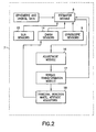
- a block diagram of the attitude control module 7 is shown in figure 2.
- the estimator module 8 contains modeling software which is capable of estimating the actual attitude of the satellite 1 from data sensed on board. Ephemeris and orbital data is up loaded and stored in the attitude control module 7 to allow the modeling software to take into consideration repetitive error causing disturbances.
- the primary source of sensed attitude data is a three axis gyroscope assembly 9. The data sensed by the gyroscopes are fed to the estimator module 8 and used to obtain an updated attitude for the satellite 1.
- the estimator module 8 uses least-square estimation techniques to combine the gyro data with the earth sensor data and sun sensor data to estimate both spacecraft attitude and gyro drift.
- the modeling software may be any of the available algorithms designed to calculate attitude from available data.
- the desired mission attitude is periodically up loaded from ground control computer 3 and stored in the attitude control module 7.
- the estimated actual attitude is compared to the mission attitude by the adjustment module 16 and an error calculation is obtained.
- This error calculation is converted to an attitude adjustment with components referencing the standard coordinate system.
- These data is converted by algorithms in the torque transformation module 17 to a four axis adjustment for actuating the four wheel actuator system 18. The latter transformation is accomplished as described in U.S. Patent No. 5,826,829, which issued on October 27, 1998, the contents of which are incorporated herein by reference.
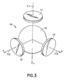
- the trihedral momentum bias (TMB) wheel configuration of the invention uses four wheels of which any three can be used to provide the momentum bias and active nadir attitude three axis pointing.
- the four wheels are comprised of one momentum wheel and three reaction wheels.
- the three reaction wheels (typically smaller than the momentum wheel) are in a trihedral configuration which can provide the backup momentum bias should the momentum wheel fail. Full three-axis control would also be maintained if any one of the reaction wheels should fail.
- the wheel system can be operated in any of five modes: one using all four wheels and four modes each of which turn off one of the four wheels. It is up to the user which of five available wheel combinations will be used for nominal operation. If the three reaction wheels are used for nominal operations. and the reaction wheels are sized properly, it is possible to achieve three-axis active attitude control without any wheels being required to spin through zero rpm.
- the trihedral wheel system 18 includes a relatively large momentum wheel 10 mounted on the satellite, which wheel is rotatable about a spin axis (not shown) for maintaining gyroscopic stiffness of the spacecraft in space about a first axis.
- the wheel system 18 also includes a plurality of relatively smaller reaction wheels 11, 12, and 13 which, like the momentum wheel 10, are mounted on the spacecraft and rotatable on spin axes 111, 112, and 113, respectively, in a fixed, trihedral, configuration. Any two of the three reaction wheels 11-13, together with the momentum wheel 10, provide full three-axis control of the spacecraft in a predetermined attitude.
- the reaction wheels are flywheels with a vehicle-fixed axis designed to operate through zero wheel speed. In the event of a failure of the momentum wheel 10, the reaction wheels 11, 12, and 13 can be used to provide angular momentum sufficient to maintain the gyroscopic stiffness lost by the failure of the momentum wheel, while maintaining full three-axis control of the spacecraft in a predetermined attitude.
- the combined angular momentum of the remaining wheels is effective to maintain gyroscopic stiffness about the first axis while also maintaining full three-axis control of the spacecraft in a predetermined attitude.
- the momentum wheel 10 and the reaction wheels 11, 12, 13 are all rotatable about relatively fixed spin axes 111, 112, and 113 in a configuration for together maintaining gyroscopic stiffness and for maintaining three-axis control of the spacecraft. The details of this configuration are described in the above cited patent which is incorporated herein.
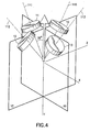
- FIG. 4 An alternative embodiment to the trihedral reaction wheel configuration, described above, is shown in figure 4.
- reaction wheels 10-13 are arranged with their spin axis 110 through 113 oblique to the y axis.
- the angle of each of the spin axes 110-113 is approximately 35°, but this could be virtually any angle depending on the amount of momentum bias needed for gyroscopic stiffness and the amount of momentum storage needed.
- Two of the spin axes are positioned in the yz plane and the other two spin axes are in the xy plane.
- the double V type of configuration also provides three axis control and three axis momentum storage by using any three of the four reaction wheels, while maintaining gyroscopic stiffness.
Landscapes
- Engineering & Computer Science (AREA)
- Remote Sensing (AREA)
- Radar, Positioning & Navigation (AREA)
- Chemical & Material Sciences (AREA)
- Combustion & Propulsion (AREA)
- Aviation & Aerospace Engineering (AREA)
- General Life Sciences & Earth Sciences (AREA)
- Geochemistry & Mineralogy (AREA)
- Geology (AREA)
- Environmental & Geological Engineering (AREA)
- Life Sciences & Earth Sciences (AREA)
- Automation & Control Theory (AREA)
- Control Of Position, Course, Altitude, Or Attitude Of Moving Bodies (AREA)
Abstract
Description
- The system of this application is designed to control the attitude of a satellite. Satellites must be maintained in a predetermined orbit and attitude in order to accomplish the assigned mission which can be surveillance, photography, detection and many others. The orbit and attitude of the satellite must be periodically adjusted to compensate for disturbances which occur in space or for the purpose of changing the mission.
- In general, spacecraft attitude is adjusted by activating actuators, such as, momentum wheels, magnetic torguers, or thrusters in response to an attitude correction signal. The attitude error may be sensed by reference to sensors monitoring the position of the sun, stars and earth relative to the satellite or by onboard inertial sensors such as gyroscopes. The attitude is adjusted to its mission orientation in which the system is pointed at its predetermined target and is maintained in this orientation during orbital flight. During flight the satellite is subject to motions induced by external forces, on board mechanisms or other sources and the attitude control system must continuously monitor and adjust attitude. Attitude control is therefore of primary importance in order to point the satellite to accomplish its mission and to maintain that position with the required accuracy.
- According to one aspect of the present invention, there is provided a control system for maintaining the attitude of a satellite in alignment with its mission attitude comprising:
- a ground station control computer constructed to transmit satellite orbital data and mission attitude data to a satellite onboard computer;
- an earth sensor array for sensing satellite position data relative to the earth;
- a sun sensor array for sensing satellite position data relative to the sun;
- a three axis gyroscope system for sensing satellite orbital position about a three axis coordinate system;
- a reaction wheel assembly having a reference axis, said wheel assemble including four wheels, each of said wheels being mounted for rotation on a spin axis, said spin axes arranged in a configuration, wherein at least three of said spin axes are oblique to said reference axis;
- an onboard satellite control computer constructed to receive and store said
orbital data and mission attitude data from the ground station computer, said
onboard computer further comprising:
- an estimator module constructed to store orbital attitude modeling algorithms and to process the orbital data and mission attitude data, the sensed earth and sun position data, and the gyroscope attitude data and is further constructed to estimate the current satellite attitude based on said data inputs;
- an adjustment module constructed to compare the mission attitude to the estimated current attitude and to calculate an attitude error; said adjustment module further calculating an attitude adjustment capable of reducing the error to substantially zero; and
- a transformation module having algorithms stored therein for converting aid attitude adjustment to an attitude command for actuating said reaction heel assembly to adjust the attitude of the satellite according to the attitude adjustment.
-
- It is a purpose of this invention to use fuel efficient reaction wheels to achieve attitude corrections wherever possible. This is accomplished while obtaining a tighter pointing capability with increased spacecraft autonomy. It is a purpose of this invention to utilize four reaction wheels preferably arranged in a trihedral configuration to provide better performance and enhanced redundancy.
- The control system of this invention employs a configuration of four reaction wheels preferably arranged in a trihedral relation as the primary attitude adjustment mechanism. The primary attitude sensors consist of a three axis gyroscope system. The control module includes stored orbital and related sun ephemeris data and appropriate estimating algorithms. The attitude is estimated with reference to the output of the three axis gyroscope system. Compensation for errors relating to gyroscope drift are provided by reference to data from on board earth and star sensors. Utilizing this data, the control module provides an estimate of the actual attitude of the satellite. The estimated attitude is compared to the desired attitude to obtain an attitude adjustment in terms of the three axis reference system. Each of the components of the adjustment is transformed to obtain the four wheel torque rates required to accomplish the adjustment. In order to further refine the estimated adjustment, the predicted three axis torque adjustments are fed back to the control module.
- According to another aspect of the present invention, there is provided a satellite including a control system therefore, said control system including a ground station computer and a satellite onboard computer, a method of correcting the attitude of the satellite utilizing a reaction wheel assembly having a reference axis, said wheel assembly including four wheels, each of said wheels being mounted for rotation on an axis, said axes arranged in a configuration, wherein at least three of said axis are oblique to said reference axis, said method comprising the steps of:
- transmitting satellite orbital data and mission attitude data to the satellite onboard computer;
- storing orbital attitude modeling algorithms in said satellite onboard computer;
- sensing satellite position data relative to the earth;
- sensing satellite position data relative to the sun;
- sensing satellite orbital position about a three axis coordinate system by means of a three axis gyroscope system;
- estimating, in the onboard computer, the current attitude of the satellite based on said orbital data, said sensed earth and sun position data, and said gyroscope attitude data, using said attitude modeling algorithms;
- comparing the mission attitude to the estimated current attitude and calculating an attitude error; and further generating an attitude adjustment based on said three axis coordinate system, capable of reducing the error to substantially zero;
- storing transforming algorithms for converting said three axes attitude adjustment to said reaction wheel assembly in said onboard computer; and,
- transforming said three axes attitude adjustment to a four axis attitude command for actuating said reaction wheel system to adjust the attitude of the satellite according to the attitude adjustment.
-
- The invention of this application is described in more detail below with reference to the Drawing in which:
- Figure 1 is a schematic illustration of a satellite system using this invention.
- Figure 2 is a block diagram of the system of this invention;
- Figure 3 is a schematic illustration of the trihedral reaction wheel configuration of this invention; and
- Figure 4 is a schematic illustration of an alternative reaction wheel configuration used in this invention.
-
- The basic components of the
satellite 1 are shown in Figure 1 and includemission sensors 2,ground control computer 3,attitude adjustment actuators 4, andonboard computer 5.Ground control computer 3 is in microwave communication with thesatellite computer 5 and transmits the attitude data required to fulfill the mission for storage incomputer 5. Themission sensors 2 may include cameras, telescopes, communications antennae and other similar devices. Theattitude adjustment actuators 4 are shown schematically as thrusters, but may also include other types of actuators, such as thrusters, momentum wheels, or magnetic torquers. In particular a system ofreaction wheels 18, as shown in figure 3, are used to supplement the thruster system. Thethrusters 4 may be used for orbit transfer maneuvers, while thereaction wheel system 18 is used for smaller station keeping adjustments. - The
satellite 1 is oriented in space by reference to three axes orthogonal coordinates. As shown in figure 1, the coordinate system includes an x axis which is generally tangent to the orbit path and referred to as the roll axis, a z axis which is generally pointed at the center of the earth and referred to as the yaw axis, and a y axis which is perpendicular to the other axes and referred to as the pitch axis. Pitch, yaw, and roll refer to rotational movement of the satellite about the particular axis. - In order to maintain the desired mission attitude a continuous monitoring of actual attitude needs to be accomplished. For this purpose an onboard attitude control module 7 is constructed as part of the
satellite control computer 5. A block diagram of the attitude control module 7 is shown in figure 2. Theestimator module 8 contains modeling software which is capable of estimating the actual attitude of thesatellite 1 from data sensed on board. Ephemeris and orbital data is up loaded and stored in the attitude control module 7 to allow the modeling software to take into consideration repetitive error causing disturbances. The primary source of sensed attitude data is a threeaxis gyroscope assembly 9. The data sensed by the gyroscopes are fed to theestimator module 8 and used to obtain an updated attitude for thesatellite 1. To allow theestimator module 8 to compensate for gyro drift, the position of thesatellite 1 with respect to the earth and sun are sensed byearth sensors 14 andsun sensors 15 on thesatellite 1. Data from these sensors are sent to theestimator module 8 and factored into the modeling calculations. The estimator module uses least-square estimation techniques to combine the gyro data with the earth sensor data and sun sensor data to estimate both spacecraft attitude and gyro drift. - The modeling software may be any of the available algorithms designed to calculate attitude from available data.
- The desired mission attitude is periodically up loaded from
ground control computer 3 and stored in the attitude control module 7. The estimated actual attitude is compared to the mission attitude by theadjustment module 16 and an error calculation is obtained. This error calculation is converted to an attitude adjustment with components referencing the standard coordinate system. These data is converted by algorithms in thetorque transformation module 17 to a four axis adjustment for actuating the fourwheel actuator system 18. The latter transformation is accomplished as described in U.S. Patent No. 5,826,829, which issued on October 27, 1998, the contents of which are incorporated herein by reference. - The trihedral momentum bias (TMB) wheel configuration of the invention uses four wheels of which any three can be used to provide the momentum bias and active nadir attitude three axis pointing. The four wheels are comprised of one momentum wheel and three reaction wheels. The three reaction wheels (typically smaller than the momentum wheel) are in a trihedral configuration which can provide the backup momentum bias should the momentum wheel fail. Full three-axis control would also be maintained if any one of the reaction wheels should fail. The wheel system can be operated in any of five modes: one using all four wheels and four modes each of which turn off one of the four wheels. It is up to the user which of five available wheel combinations will be used for nominal operation. If the three reaction wheels are used for nominal operations. and the reaction wheels are sized properly, it is possible to achieve three-axis active attitude control without any wheels being required to spin through zero rpm.
- The
trihedral wheel system 18 includes a relativelylarge momentum wheel 10 mounted on the satellite, which wheel is rotatable about a spin axis (not shown) for maintaining gyroscopic stiffness of the spacecraft in space about a first axis. - The
wheel system 18 also includes a plurality of relativelysmaller reaction wheels momentum wheel 10, are mounted on the spacecraft and rotatable onspin axes momentum wheel 10, provide full three-axis control of the spacecraft in a predetermined attitude. The reaction wheels are flywheels with a vehicle-fixed axis designed to operate through zero wheel speed. In the event of a failure of themomentum wheel 10, thereaction wheels momentum wheel 10 and thereaction wheels - An alternative embodiment to the trihedral reaction wheel configuration, described above, is shown in figure 4. In this four wheel reaction wheel system 19, reaction wheels 10-13 are arranged with their
spin axis 110 through 113 oblique to the y axis. As shown, the angle of each of the spin axes 110-113 is approximately 35°, but this could be virtually any angle depending on the amount of momentum bias needed for gyroscopic stiffness and the amount of momentum storage needed. Two of the spin axes are positioned in the yz plane and the other two spin axes are in the xy plane. Similarly to the trihedral configuration, the double V type of configuration also provides three axis control and three axis momentum storage by using any three of the four reaction wheels, while maintaining gyroscopic stiffness.
Claims (4)
- A control system for maintaining the attitude of a satellite in alignment with its mission attitude comprising:a ground station control computer (3) constructed to transmit satellite orbital data and mission attitude data to a satellite onboard computer (5);an earth sensor array (14) for sensing satellite position data relative to the earth;a sun sensor array (15) for sensing satellite position data relative to the sun;a three axis gyroscope system (9) for sensing satellite orbital position about a three axis coordinate system;a reaction wheel assembly (18) having a reference axis, said wheel assemble including four wheels (10-13), each of said wheels being mounted for rotation on a spin axis, said spin axes arranged in a configuration, wherein at least three of said spin axes are oblique to said reference axis;an onboard satellite control computer (5) constructed to receive and store said orbital data and mission attitude data from the ground station computer (3), said onboard computer further comprising:an estimator module (8) constructed to store orbital attitude modeling algorithms and to process the orbital data and mission attitude data, the sensed earth and sun position data, and the gyroscope attitude data and is further constructed to estimate the current satellite attitude based on said data inputs;an adjustment module (16) constructed to compare the mission attitude to the estimated current attitude and to calculate an attitude error; said adjustment module further calculating an attitude adjustment capable of reducing the error to substantially zero; anda transformation module (17) having algorithms stored therein for converting aid attitude adjustment to an attitude command for actuating said reaction heel assembly to adjust the attitude of the satellite according to the attitude adjustment.
- A control system for maintaining the attitude of a satellite in alignment with its mission attitude, as described in claim 1, wherein one of said spin axis of said reaction wheels is the reference axis.
- A control system for maintaining the attitude of a satellite in alignment with its mission attitude, as described in claim 1, wherein all of the reaction wheel spin axis are oblique to the reference axis.
- In a satellite including a control system therefore, said control system including a ground station computer and a satellite onboard computer, a method of correcting the attitude of the satellite utilizing a reaction wheel assembly having a reference axis, said wheel assembly including four wheels, each of said wheels being mounted for rotation on an axis, said axes arranged in a configuration, wherein at least three of said axis are oblique to said reference axis, said method comprising the steps of:transmitting satellite orbital data and mission attitude data to the satellite onboard computer;storing orbital attitude modeling algorithms in said satellite onboard computer;sensing satellite position data relative to the earth;sensing satellite position data relative to the sun;sensing satellite orbital position about a three axis coordinate system by means of a three axis gyroscope system;estimating, in the onboard computer, the current attitude of the satellite based on said orbital data, said sensed earth and sun position data, and said gyroscope attitude data, using said attitude modeling algorithms;comparing the mission attitude to the estimated current attitude and calculating an attitude error; and further generating an attitude adjustment based on said three axis coordinate system, capable of reducing the error to substantially zero;storing transforming algorithms for converting said three axes attitude adjustment to said reaction wheel assembly in said onboard computer; and,transforming said three axes attitude adjustment to a four axis attitude command for actuating said reaction wheel system to adjust the attitude of the satellite according to the attitude adjustment.
Applications Claiming Priority (2)
| Application Number | Priority Date | Filing Date | Title |
|---|---|---|---|
| US478787 | 2000-01-06 | ||
| US09/478,787 US6285928B1 (en) | 2000-01-06 | 2000-01-06 | Onboard attitude control using reaction wheels |
Publications (2)
| Publication Number | Publication Date |
|---|---|
| EP1114774A2 true EP1114774A2 (en) | 2001-07-11 |
| EP1114774A3 EP1114774A3 (en) | 2002-07-31 |
Family
ID=23901348
Family Applications (1)
| Application Number | Title | Priority Date | Filing Date |
|---|---|---|---|
| EP00311287A Withdrawn EP1114774A3 (en) | 2000-01-06 | 2000-12-15 | Onboard attitude control system using reaction wheels |
Country Status (3)
| Country | Link |
|---|---|
| US (1) | US6285928B1 (en) |
| EP (1) | EP1114774A3 (en) |
| JP (1) | JP2001240000A (en) |
Cited By (5)
| Publication number | Priority date | Publication date | Assignee | Title |
|---|---|---|---|---|
| CN106240846A (en) * | 2015-06-15 | 2016-12-21 | 波音公司 | Vehicles gesture stability |
| CN106774280A (en) * | 2017-01-22 | 2017-05-31 | 上海航天控制技术研究所 | Method for automatic fault diagnosis on a kind of counteraction flyback star |
| EP3088981A4 (en) * | 2014-05-27 | 2017-09-13 | Beijing Aerospace Wanda Hi-Tech Ltd. | Non-orthogonal six-rod satellite communication in motion servo system and control method |
| CN109444917A (en) * | 2018-10-09 | 2019-03-08 | 中国人民解放军国防科技大学 | Space station external structure detection and maintenance system and method based on micro-nano satellite cluster |
| CN110329548A (en) * | 2019-05-24 | 2019-10-15 | 中国人民解放军63789部队 | In-orbit turn of biasing of spacecraft controls lower fly wheel system reconstructing method |
Families Citing this family (21)
| Publication number | Priority date | Publication date | Assignee | Title |
|---|---|---|---|---|
| US6691955B2 (en) * | 2001-11-27 | 2004-02-17 | Space Systems/Loral | Spacecraft having a momentum wheel configuration that prevents zero wheel speeds |
| US6732977B1 (en) | 2002-02-11 | 2004-05-11 | Lockheed Martin Corporation | System for on-orbit correction of spacecraft payload pointing errors |
| US6695263B1 (en) | 2002-02-12 | 2004-02-24 | Lockheed Martin Corporation | System for geosynchronous spacecraft rapid earth reacquisition |
| US7051980B2 (en) * | 2002-02-26 | 2006-05-30 | Lockheed Martin Corporation | Efficient orbit sparing system for space vehicle constellations |
| US6600976B1 (en) * | 2002-03-29 | 2003-07-29 | Lockheed Martin Corporation | Gyroless control system for zero-momentum three-axis stabilized spacecraft |
| US6702234B1 (en) | 2002-03-29 | 2004-03-09 | Lockheed Martin Corporation | Fault tolerant attitude control system for zero momentum spacecraft |
| WO2004007287A2 (en) * | 2002-07-16 | 2004-01-22 | The Charles Stark Draper Laboratory, Inc. | Integrated inertial stellar attitude sensor |
| US7835826B1 (en) | 2005-12-13 | 2010-11-16 | Lockheed Martin Corporation | Attitude determination system for yaw-steering spacecraft |
| KR100932156B1 (en) * | 2007-12-24 | 2009-12-16 | 한국항공우주연구원 | Reaction Wheel Momentum Distribution Method Using Zero Space Vector |
| JP4697254B2 (en) * | 2008-04-02 | 2011-06-08 | トヨタ自動車株式会社 | Vehicle behavior control device |
| US8209065B2 (en) * | 2009-01-21 | 2012-06-26 | The Boeing Company | Steering logic for spacecraft slew maneuvers |
| US8321076B2 (en) * | 2009-12-18 | 2012-11-27 | The Boeing Company | On-line inertia estimation for use in controlling an aerospace vehicle |
| US8763957B1 (en) * | 2012-10-08 | 2014-07-01 | Space Systems/Loral, Llc | Spacecraft transfer orbit techniques |
| US9073648B2 (en) * | 2013-02-15 | 2015-07-07 | The Boeing Company | Star tracker rate estimation with kalman filter enhancement |
| JP2015074382A (en) * | 2013-10-10 | 2015-04-20 | 三菱重工業株式会社 | Attitude detection device, attitude detection method, and attitude detection program |
| US10533856B2 (en) | 2017-04-05 | 2020-01-14 | Novatel Inc. | Navigation system utilizing yaw rate constraint during inertial dead reckoning |
| CN108791955B (en) * | 2018-06-14 | 2020-03-06 | 上海卫星工程研究所 | Sun evading method for static remote sensing satellite camera |
| CN112758359A (en) * | 2021-01-20 | 2021-05-07 | 北京国电高科科技有限公司 | Area coverage control method for bias momentum satellite |
| CN112896556B (en) * | 2021-03-23 | 2024-07-19 | 湖南揽月机电科技有限公司 | Array type satellite intelligent attitude control assembly and working method thereof |
| CN112937920B (en) * | 2021-03-30 | 2024-07-19 | 湖南揽月机电科技有限公司 | Multi-redundancy satellite intelligent attitude control assembly and working method thereof |
| CN115848647B (en) * | 2022-08-10 | 2023-06-27 | 北京星河动力装备科技有限公司 | Solid carrier rocket and rail-remaining last sub-stage thereof |
Citations (1)
| Publication number | Priority date | Publication date | Assignee | Title |
|---|---|---|---|---|
| US5826829A (en) | 1996-07-15 | 1998-10-27 | Space Systems/Loral Inc. | Spacecraft control system with a trihedral momentum bias wheel configuration |
Family Cites Families (16)
| Publication number | Priority date | Publication date | Assignee | Title |
|---|---|---|---|---|
| US3999729A (en) | 1975-03-20 | 1976-12-28 | Rca Corporation | Backup wheel for a three axis reaction wheel spacecraft |
| US4071211A (en) * | 1976-09-23 | 1978-01-31 | Rca Corporation | Momentum biased active three-axis satellite attitude control system |
| FR2637565B1 (en) | 1988-10-06 | 1991-01-11 | Aerospatiale | ACTIVE CONTROL SYSTEM BASED ON THREE AXES OF THE ATTITUDE OF A GEOSTATIONARY SATELLITE |
| US5020745A (en) | 1989-12-20 | 1991-06-04 | General Electric Company | Reaction wheel fricton compensation using dither |
| US5098041A (en) * | 1990-06-07 | 1992-03-24 | Hughes Aircraft Company | Attitude control system for momentum-biased spacecraft |
| US5058835A (en) | 1990-06-11 | 1991-10-22 | General Electric Company | Wheel speed management control system for spacecraft |
| US5130931A (en) | 1990-07-13 | 1992-07-14 | General Electric Company | Spacecraft attitude and velocity control system |
| FR2670746B1 (en) * | 1990-12-21 | 1993-04-16 | Aerospatiale | ATTITUDE MONITORING SYSTEM FOR 3-AXIS SATELLITE ,; IN PARTICULAR FOR OBSERVATION SATELLITE. |
| US5201833A (en) | 1991-07-19 | 1993-04-13 | General Electric Company | Attitude control system with reaction wheel friction compensation |
| US5205518A (en) * | 1991-11-25 | 1993-04-27 | General Electric Co. | Gyroless yaw control system for a three axis stabilized, zero-momentum spacecraft |
| US5308024A (en) | 1992-07-20 | 1994-05-03 | General Electric Co. | Disturbance torque compensated three axis yaw control system |
| US5452869A (en) * | 1992-12-18 | 1995-09-26 | Hughes Aircraft Company | On-board three-axes attitude determination and control system |
| US5556058A (en) * | 1994-05-16 | 1996-09-17 | Hughes Electronics | Spacecraft attitude determination using sun sensor, earth sensor, and space-to-ground link |
| EP0795806B1 (en) * | 1995-08-11 | 2001-12-05 | Astrium GmbH | Apparatus and method for attitude control and stabilisation of a spacecraft |
| US6012000A (en) * | 1998-01-14 | 2000-01-04 | Space Systems/Loral, Inc. | Simplified onboard attitude control based on star sensing |
| US6145790A (en) * | 1998-09-22 | 2000-11-14 | Hughes Electronics Corporation | Attitude determination system and method |
-
2000
- 2000-01-06 US US09/478,787 patent/US6285928B1/en not_active Expired - Lifetime
- 2000-12-15 EP EP00311287A patent/EP1114774A3/en not_active Withdrawn
-
2001
- 2001-01-05 JP JP2001000470A patent/JP2001240000A/en active Pending
Patent Citations (1)
| Publication number | Priority date | Publication date | Assignee | Title |
|---|---|---|---|---|
| US5826829A (en) | 1996-07-15 | 1998-10-27 | Space Systems/Loral Inc. | Spacecraft control system with a trihedral momentum bias wheel configuration |
Cited By (7)
| Publication number | Priority date | Publication date | Assignee | Title |
|---|---|---|---|---|
| EP3088981A4 (en) * | 2014-05-27 | 2017-09-13 | Beijing Aerospace Wanda Hi-Tech Ltd. | Non-orthogonal six-rod satellite communication in motion servo system and control method |
| CN106240846A (en) * | 2015-06-15 | 2016-12-21 | 波音公司 | Vehicles gesture stability |
| CN106240846B (en) * | 2015-06-15 | 2021-10-01 | 波音公司 | Vehicle attitude control |
| CN106774280A (en) * | 2017-01-22 | 2017-05-31 | 上海航天控制技术研究所 | Method for automatic fault diagnosis on a kind of counteraction flyback star |
| CN106774280B (en) * | 2017-01-22 | 2019-01-18 | 上海航天控制技术研究所 | Method for automatic fault diagnosis on a kind of counteraction flyback star |
| CN109444917A (en) * | 2018-10-09 | 2019-03-08 | 中国人民解放军国防科技大学 | Space station external structure detection and maintenance system and method based on micro-nano satellite cluster |
| CN110329548A (en) * | 2019-05-24 | 2019-10-15 | 中国人民解放军63789部队 | In-orbit turn of biasing of spacecraft controls lower fly wheel system reconstructing method |
Also Published As
| Publication number | Publication date |
|---|---|
| US6285928B1 (en) | 2001-09-04 |
| EP1114774A3 (en) | 2002-07-31 |
| JP2001240000A (en) | 2001-09-04 |
Similar Documents
| Publication | Publication Date | Title |
|---|---|---|
| US6285928B1 (en) | Onboard attitude control using reaction wheels | |
| US5184790A (en) | Two-axis attitude correction for orbit inclination | |
| EP0683098B1 (en) | Spacecraft attitude determination using sun sensor, earth sensor and space-to-ground link | |
| EP0769736B1 (en) | Method for inclined orbit attitude control for momentum bias spacecraft | |
| US9108749B2 (en) | Spacecraft momentum management | |
| US7823836B2 (en) | Optimal sun safe attitude for satellite ground tracking | |
| US6341249B1 (en) | Autonomous unified on-board orbit and attitude control system for satellites | |
| US8113468B2 (en) | Precision attitude control system for gimbaled thruster | |
| EP0792800B1 (en) | Single axis correction for orbit inclination | |
| US8056863B2 (en) | Unified attitude control for spacecraft transfer orbit operations | |
| US6615117B2 (en) | Attitude determination system and method with outer-loop gyro scale-factor non-linearity calibration | |
| US20080315039A1 (en) | System and methods for space vehicle torque balancing | |
| US7877173B2 (en) | Method and apparatus for determining a satellite attitude using crosslink reference signals | |
| US6360996B1 (en) | Steering control for skewed scissors pair CMG clusters | |
| US7062363B2 (en) | Refinement of spacecraft angular velocity and attitude estimates using star data | |
| JPH11291997A (en) | Satellite-borne attitude control device based on sensing of fixed star | |
| US6441776B1 (en) | Method and apparatus for spacecraft payload pointing registration | |
| US5978716A (en) | Satellite imaging control system for non-repeatable error | |
| US6142423A (en) | Ephemeris/attitude reference determination using on-board optics and other satellite ephemeris | |
| JP2002080000A (en) | Correction of operation control rule for satellite due to influence of unexpected orbital inclination | |
| EP0544241A1 (en) | Method and apparatus for dynamic precompensation of solar wing stepping motions of a satellite | |
| US20230415925A1 (en) | Maneuvering of satellites without rate sensors | |
| Strikwerda et al. | The NEAR Guidance and Control System | |
| Hacker et al. | Globalstar second generation hybrid attitude control on-orbit experience | |
| Ohkami et al. | Overview of the Attitude and Orbit Control Systems (AOCS) Developed for NASDA/JAXA Engineering Test and Applications Satellites |
Legal Events
| Date | Code | Title | Description |
|---|---|---|---|
| PUAI | Public reference made under article 153(3) epc to a published international application that has entered the european phase |
Free format text: ORIGINAL CODE: 0009012 |
|
| AK | Designated contracting states |
Kind code of ref document: A2 Designated state(s): AT BE CH CY DE DK ES FI FR GB GR IE IT LI LU MC NL PT SE TR |
|
| AX | Request for extension of the european patent |
Free format text: AL;LT;LV;MK;RO;SI |
|
| PUAL | Search report despatched |
Free format text: ORIGINAL CODE: 0009013 |
|
| AK | Designated contracting states |
Kind code of ref document: A3 Designated state(s): AT BE CH CY DE DK ES FI FR GB GR IE IT LI LU MC NL PT SE TR |
|
| AX | Request for extension of the european patent |
Free format text: AL;LT;LV;MK;RO;SI |
|
| GRAH | Despatch of communication of intention to grant a patent |
Free format text: ORIGINAL CODE: EPIDOS IGRA |
|
| 17P | Request for examination filed |
Effective date: 20030129 |
|
| AKX | Designation fees paid |
Designated state(s): DE FR GB IT |
|
| STAA | Information on the status of an ep patent application or granted ep patent |
Free format text: STATUS: THE APPLICATION HAS BEEN WITHDRAWN |
|
| 18W | Application withdrawn |
Effective date: 20030709 |