EP1114766A2 - Verstellmechanismus für die Radstellungswinkel von Rädern eines Raupenfahrzeuges - Google Patents
Verstellmechanismus für die Radstellungswinkel von Rädern eines Raupenfahrzeuges Download PDFInfo
- Publication number
- EP1114766A2 EP1114766A2 EP00127866A EP00127866A EP1114766A2 EP 1114766 A2 EP1114766 A2 EP 1114766A2 EP 00127866 A EP00127866 A EP 00127866A EP 00127866 A EP00127866 A EP 00127866A EP 1114766 A2 EP1114766 A2 EP 1114766A2
- Authority
- EP
- European Patent Office
- Prior art keywords
- tension link
- alignment cam
- adjustment mechanism
- toe
- frame
- Prior art date
- Legal status (The legal status is an assumption and is not a legal conclusion. Google has not performed a legal analysis and makes no representation as to the accuracy of the status listed.)
- Granted
Links
- 230000007246 mechanism Effects 0.000 title claims abstract description 19
- 230000000712 assembly Effects 0.000 description 2
- 238000000429 assembly Methods 0.000 description 2
- 230000005540 biological transmission Effects 0.000 description 2
- 238000011161 development Methods 0.000 description 2
- 230000018109 developmental process Effects 0.000 description 2
- 229910000831 Steel Inorganic materials 0.000 description 1
- 238000002485 combustion reaction Methods 0.000 description 1
- 230000001419 dependent effect Effects 0.000 description 1
- 239000010959 steel Substances 0.000 description 1
Images


Classifications
-
- B—PERFORMING OPERATIONS; TRANSPORTING
- B62—LAND VEHICLES FOR TRAVELLING OTHERWISE THAN ON RAILS
- B62D—MOTOR VEHICLES; TRAILERS
- B62D55/00—Endless track vehicles
- B62D55/08—Endless track units; Parts thereof
- B62D55/30—Track-tensioning means
- B62D55/305—Track-tensioning means acting on pivotably mounted idlers
Definitions
- the invention is directed to an adjustment mechanism for adjusting the toe-in/toe-out orientation of a wheel. It is particularly well adapted for adjusting the toe-in/toe-out orientation of an idler on a belted tracked vehicle.
- the invention is also directed to a track vehicle with an adjustment mechanism.
- Track vehicles comprise a vehicle main frame having a track frame extending therefrom.
- An engine powers a transmission that drives two drive wheels extending out each side of the vehicle.
- the track frame is provided with two idlers spaced along a longitudinal axis from the drive wheels.
- the track frame has left and right sides that may be rigidly joined together, or joined together by an equalizer bar or axle.
- a track is entrained about each drive wheel/idler pair.
- Track rollers may also extend downwardly from the track frame to run on the track and distribute the weight of the vehicle.
- the track can be conventional steel crawler chain to which grouser plates are attached, rubber belted tracks of the type used on agricultural tractors, or ladder tracks wherein a flexible cables or chains are coupled to one another by transversely extending members.
- the idler is rotatively mounted to a tension link.
- the idler defines a transverse axis.
- the tension link in turn is pivotally coupled to a J-link.
- the pivot axis of the tension link relative to the idler is parallel to the transverse axis of the idler.
- the J-link in turn is pivotally coupled to the track frame.
- the J-link is pivotable about a vertical axis.
- the J-link can be pivoted and locked in place by two screws extending inwardly from the sides of the track frame.
- an adjustment mechanism is mounted to a frame and comprises an alignment cam having a tension link pivot pin.
- the alignment cam and tension link pivot pin being either a single integral part, or two separate parts.
- the alignment cam is provided with an actuating arm that is coupled to a longitudinally extendible adjusting member.
- the longitudinally extendible adjusting member comprising a screw jack.
- a tension link is pivotally mounted to the tension link pivot pin. Camming surfaces on the alignment cam are skewed with respect to the transverse axis defined by the tension link pivot pin so that rotation of the alignment cam twists the tension link and thereby the idler wheel predominately about a vertical axis.
- rotation of the alignment cam also twists the tension link and idler about a longitudinally extending horizontal axis and relative to the frame. Therefore by extending or retracting the screw jack, the toe-in/toe-out orientation of the idler wheel can be adjusted.
- Fig. 1 illustrates a large track vehicle 10 having a main frame 12 and a track frame 14.
- the vehicle is provided with a pair of drive wheels 16 and a pair of idler wheels 18.
- a track 20 comprising an inextensible elastomeric belt is entrained about the drive wheels 16 and the idler wheels 18.
- the exterior of the belt is provided with ground engaging cleats and the interior of the belt is provided with centering guide lugs.
- the track frame is also provided with midwheels 22 for better distributing the load of the vehicle on the ground.
- the track frame 14 maybe provided with an equalizer bar to distribute load between the left and right segments of the track frame 14.
- the drive wheels 16 are driven by an internal combustion engine and transmission, not shown, that are mounted to the main frame 12. The operation of the vehicle is controlled from operator's cab 24.
- the track vehicle 10 is also provided with an implement hitch 26.
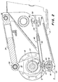
- the track frame 14 is provided with a tension link 30, best illustrated in Figures 2 and 3, that is pivotally coupled to the track frame 14 at pivot 32.
- the top of the link is pivotally coupled to a hydraulic cylinder 34, which rotates tension link 30 about pivot 32 to control the tension in track 20.
- the hydraulic cylinder 34 is pivotally coupled to the track frame 14 at pivot 36 and to the tension link 30 at pivot 38.
- the idler wheel 18 is rotatively coupled to an axle 37 extending through the tension link 30 between pivot 32 and pivot 38. By extending the hydraulic cylinder 34, the idler wheel 18 is moved away from the drive wheel 16 adding tension to the track 20.
- the hydraulic cylinder 34 is hydraulically coupled to an accumulator to maintain a more consistent pressure in the hydraulic cylinder and thereby a consistent tension on the track even when objects get trapped between the track and the wheels.
- the hydraulic cylinder forms a linear motor for pivoting the tension link, however other linear motor assemblies maybe acceptable for different applications.
- Tension link pivot 32 is provided with a cylindrical transversely arranged alignment cam 40 which is rotatively mounted in journals 41 machined into the track frame 14.
- a tension link pivot pin 42 extends through a transverse bore formed in the alignment cam 40.
- the tension link pivot pin 42 and the alignment cam 40 are two separate parts, however these parts could be integrally formed into a single part.
- a bore perpendicular to the tension link pivot pin 42 is formed through the track frame pivot pin 42 and the alignment cam 40 for receiving an actuating arm 44.
- the actuating arm 44 extends upwardly from the alignment cam 40 and is provided with a yoke 47 that is pinned to a longitudinally extendible adjusting member 46 by clevis pin 48.
- Adjusting member 46 is a screw jack formed by a hollow shaft 50 having a sleeve 52 that encircles pin 48.
- the hollow shaft 50 has a threaded portion that engages threaded member 54.
- Threaded member 54 is mounted to the track frame 14 by a ball joint 56.
- the ball joint 56 is formed by a spherical portion 57 formed in the threaded member 54 that is trapped between two plates 59 extending into the hollow interior of the track frame 14 from one of its interior surfaces.
- the end of the threaded member 54 opposite the threaded portion is provided with a hex nut head 58, which can be rotated by a conventional wrench.
- the hex nut head 58 can be accessed through an opening formed in the track frame 14 for that purpose.
- the longitudinally extendible adjustment member 46 could comprise other suitable assemblies, such as electrically driven linear motors, hydraulic motors and other linear extendible mechanisms.
Landscapes
- Engineering & Computer Science (AREA)
- Chemical & Material Sciences (AREA)
- Combustion & Propulsion (AREA)
- Transportation (AREA)
- Mechanical Engineering (AREA)
- Body Structure For Vehicles (AREA)
Applications Claiming Priority (2)
| Application Number | Priority Date | Filing Date | Title |
|---|---|---|---|
| US478379 | 2000-01-06 | ||
| US09/478,379 US6273530B1 (en) | 2000-01-06 | 2000-01-06 | Toe-in/toe-out adjustment mechanism |
Publications (3)
| Publication Number | Publication Date |
|---|---|
| EP1114766A2 true EP1114766A2 (de) | 2001-07-11 |
| EP1114766A3 EP1114766A3 (de) | 2001-11-14 |
| EP1114766B1 EP1114766B1 (de) | 2012-09-26 |
Family
ID=23899695
Family Applications (1)
| Application Number | Title | Priority Date | Filing Date |
|---|---|---|---|
| EP00127866A Expired - Lifetime EP1114766B1 (de) | 2000-01-06 | 2000-12-20 | Verstellmechanismus für die Radstellungswinkel von Rädern eines Raupenfahrzeuges |
Country Status (3)
| Country | Link |
|---|---|
| US (1) | US6273530B1 (de) |
| EP (1) | EP1114766B1 (de) |
| AU (1) | AU7226500A (de) |
Cited By (3)
| Publication number | Priority date | Publication date | Assignee | Title |
|---|---|---|---|---|
| WO2010071552A1 (en) * | 2008-12-16 | 2010-06-24 | BAE Systems Hägglunds Aktiebolag | Arrangement for controlling a track tension wheel of a tracked vehicle |
| CN104875799A (zh) * | 2015-05-31 | 2015-09-02 | 南京理工大学 | 前导轮角度可变的小型固定式履带车 |
| US20240101200A1 (en) * | 2022-09-26 | 2024-03-28 | Howe & Howe Inc. | Tracked vehicle tensioning |
Families Citing this family (16)
| Publication number | Priority date | Publication date | Assignee | Title |
|---|---|---|---|---|
| US7740084B2 (en) | 2000-05-02 | 2010-06-22 | Lyn Rosenboom | Agricultural implement frame, track assembly and cart |
| GB2367542B (en) * | 2000-10-04 | 2003-07-09 | Joy Mm Delaware Inc | Tracked vehicle and tension adjustment assembly |
| US7726749B2 (en) * | 2001-05-02 | 2010-06-01 | Lyn Rosenboom | Track assembly with bogie wheel structure |
| US7380892B2 (en) * | 2001-05-02 | 2008-06-03 | Lyn Rosenboom | Track assembly with idler wheels and cart incorporating same |
| US6857816B2 (en) * | 2001-06-20 | 2005-02-22 | Sakai Heavy Industries, Ltd. | Roller |
| SE525073C2 (sv) * | 2003-04-09 | 2004-11-23 | Alvis Haegglunds Ab | Anordning för manövrering av ett spännhjul hos ett bandfordon |
| US20060220456A1 (en) * | 2003-08-19 | 2006-10-05 | Shingo Sugahara | Rubber crawler traveling device |
| SE529600C2 (sv) * | 2006-02-08 | 2007-10-02 | Bae Systems Haegglunds Ab | Spännhjulsanordning |
| US20110031713A1 (en) * | 2009-08-04 | 2011-02-10 | Ekbundit Michael W | Rod end mounting bushing |
| CA2744630C (en) | 2010-06-30 | 2018-10-09 | Camoplast Solideal Inc. | Wheel of a track assembly of a tracked vehicle |
| US9505454B1 (en) | 2011-06-13 | 2016-11-29 | Camso Inc. | Track assembly for traction of an off-road vehicle |
| US9469356B2 (en) * | 2012-12-21 | 2016-10-18 | Agco Corporation | Multi-axis reaction arm assembly for a tracked tractor |
| US10875591B2 (en) | 2015-08-04 | 2020-12-29 | Camso Inc. | Track system for traction of an agricultural vehicle travelling on fields and roads |
| US9988111B2 (en) | 2016-08-04 | 2018-06-05 | Caterpillar Inc. | Swing arm idler rise height adjustment |
| WO2019162927A1 (en) | 2018-02-26 | 2019-08-29 | Soucy International Inc. | Track system |
| CA3264770A1 (en) * | 2022-09-02 | 2024-03-07 | Soucy International Inc. | TRACK SYSTEM ADJUSTMENT KIT AND TRACK SYSTEM FEATURING THE LATTER |
Family Cites Families (14)
| Publication number | Priority date | Publication date | Assignee | Title |
|---|---|---|---|---|
| CH375958A (de) * | 1959-08-11 | 1964-03-15 | Maag Zahnraeder & Maschinen Ag | Verstellbare Radiallagerung eines Zahnrades innerhalb eines Gehäuses |
| US3275386A (en) * | 1964-08-04 | 1966-09-27 | Int Harvester Co | Crawler tractor suspension |
| US4405026A (en) * | 1980-10-30 | 1983-09-20 | Lockheed Missiles & Space Company, Inc. | Mounting mechanism for endless traction band system |
| JPS592974A (ja) * | 1982-06-26 | 1984-01-09 | Toshiba Corp | 4輪クロ−ラ走行車 |
| FR2537247B3 (fr) * | 1982-12-02 | 1985-12-13 | Ziffel Alain | Dispositif correcteur anti-vissage, pour un vireur de chaudronnerie |
| US4537267A (en) | 1983-12-20 | 1985-08-27 | Caterpillar Tractor Co. | Belt tensioning mechanism |
| SU1493528A1 (ru) * | 1985-10-29 | 1989-07-15 | Челябинский Тракторный Завод Им.В.И.Ленина | Подвеска трактора |
| US4834478A (en) * | 1988-06-30 | 1989-05-30 | Caterpillar Inc. | Track roller frame assembly |
| US5072800A (en) * | 1990-04-24 | 1991-12-17 | Caterpillar Inc. | Support beam for a vehicle |
| US5127714A (en) * | 1991-02-04 | 1992-07-07 | Caterpillar Inc. | Belt alignment mechanism for a belt driven vehicle |
| US5293948A (en) * | 1992-09-25 | 1994-03-15 | Caterpillar Inc. | Undercarriage assembly for a vehicle |
| US5279377A (en) * | 1993-04-12 | 1994-01-18 | Caterpillar Inc. | Track-type vehicle undercarriage |
| US5639148A (en) | 1996-04-17 | 1997-06-17 | Deere & Company | Undercarriage adjustment mechanism for a tracked vehicle |
| US5927412A (en) * | 1997-01-14 | 1999-07-27 | Caterpillar Inc. | Castering swing link for a track sub-assembly |
-
2000
- 2000-01-06 US US09/478,379 patent/US6273530B1/en not_active Expired - Lifetime
- 2000-12-14 AU AU72265/00A patent/AU7226500A/en not_active Abandoned
- 2000-12-20 EP EP00127866A patent/EP1114766B1/de not_active Expired - Lifetime
Non-Patent Citations (1)
| Title |
|---|
| None |
Cited By (4)
| Publication number | Priority date | Publication date | Assignee | Title |
|---|---|---|---|---|
| WO2010071552A1 (en) * | 2008-12-16 | 2010-06-24 | BAE Systems Hägglunds Aktiebolag | Arrangement for controlling a track tension wheel of a tracked vehicle |
| US8708431B2 (en) | 2008-12-16 | 2014-04-29 | BAE Systems Hägglunds Aktiebolag | Arrangement for controlling a track tension wheel of tracked vehicle |
| CN104875799A (zh) * | 2015-05-31 | 2015-09-02 | 南京理工大学 | 前导轮角度可变的小型固定式履带车 |
| US20240101200A1 (en) * | 2022-09-26 | 2024-03-28 | Howe & Howe Inc. | Tracked vehicle tensioning |
Also Published As
| Publication number | Publication date |
|---|---|
| AU7226500A (en) | 2001-07-12 |
| US6273530B1 (en) | 2001-08-14 |
| EP1114766A3 (de) | 2001-11-14 |
| EP1114766B1 (de) | 2012-09-26 |
Similar Documents
| Publication | Publication Date | Title |
|---|---|---|
| US6273530B1 (en) | Toe-in/toe-out adjustment mechanism | |
| US4681177A (en) | Method and apparatus for tensioning frictionally driven, ground engaging belts | |
| US5409305A (en) | Undercarriage for a track laying vehicle | |
| US11572112B2 (en) | Track system for traction of a vehicle | |
| US6116362A (en) | Articulated vehicle | |
| US5533587A (en) | Track vehicles and power drive apparatus for motivating tracked vehicles | |
| US6601664B2 (en) | Crawler device for a crawler type vehicle | |
| US6318484B2 (en) | Tracked suspension | |
| US5340205A (en) | Suspension system for a tracked vehicle | |
| US10150523B2 (en) | Tractor with track drive | |
| US20140125118A1 (en) | Track suspension | |
| KR960015712B1 (ko) | 후륜조타장치 | |
| AU564883B2 (en) | Belt tensioning mechanism | |
| EP0396548A4 (en) | Suspension structure for a tracked vehicle | |
| US10099733B1 (en) | Endless track and guide member | |
| US9555830B2 (en) | Axle assembly for a vehicle with a double kingpin hinge arrangement | |
| JPH06234375A (ja) | ベルト装軌多目的トレーラ | |
| USRE32442E (en) | Belt tensioning mechanism | |
| AU663209B2 (en) | Improvements in and relating to track laying vehicles |
Legal Events
| Date | Code | Title | Description |
|---|---|---|---|
| PUAI | Public reference made under article 153(3) epc to a published international application that has entered the european phase |
Free format text: ORIGINAL CODE: 0009012 |
|
| AK | Designated contracting states |
Kind code of ref document: A2 Designated state(s): DE FR GB IT Kind code of ref document: A2 Designated state(s): AT BE CH CY DE DK ES FI FR GB GR IE IT LI LU MC NL PT SE TR |
|
| AX | Request for extension of the european patent |
Free format text: AL;LT;LV;MK;RO;SI |
|
| PUAL | Search report despatched |
Free format text: ORIGINAL CODE: 0009013 |
|
| AK | Designated contracting states |
Kind code of ref document: A3 Designated state(s): AT BE CH CY DE DK ES FI FR GB GR IE IT LI LU MC NL PT SE TR |
|
| AX | Request for extension of the european patent |
Free format text: AL;LT;LV;MK;RO;SI |
|
| 17P | Request for examination filed |
Effective date: 20020514 |
|
| AKX | Designation fees paid |
Free format text: DE FR GB IT |
|
| 17Q | First examination report despatched |
Effective date: 20030724 |
|
| GRAP | Despatch of communication of intention to grant a patent |
Free format text: ORIGINAL CODE: EPIDOSNIGR1 |
|
| GRAS | Grant fee paid |
Free format text: ORIGINAL CODE: EPIDOSNIGR3 |
|
| GRAA | (expected) grant |
Free format text: ORIGINAL CODE: 0009210 |
|
| AK | Designated contracting states |
Kind code of ref document: B1 Designated state(s): DE FR GB IT |
|
| REG | Reference to a national code |
Ref country code: GB Ref legal event code: FG4D |
|
| REG | Reference to a national code |
Ref country code: DE Ref legal event code: R096 Ref document number: 60047513 Country of ref document: DE Effective date: 20121122 |
|
| PLBE | No opposition filed within time limit |
Free format text: ORIGINAL CODE: 0009261 |
|
| STAA | Information on the status of an ep patent application or granted ep patent |
Free format text: STATUS: NO OPPOSITION FILED WITHIN TIME LIMIT |
|
| 26N | No opposition filed |
Effective date: 20130627 |
|
| REG | Reference to a national code |
Ref country code: DE Ref legal event code: R097 Ref document number: 60047513 Country of ref document: DE Effective date: 20130627 |
|
| REG | Reference to a national code |
Ref country code: FR Ref legal event code: PLFP Year of fee payment: 16 |
|
| REG | Reference to a national code |
Ref country code: FR Ref legal event code: PLFP Year of fee payment: 17 |
|
| PG25 | Lapsed in a contracting state [announced via postgrant information from national office to epo] |
Ref country code: IT Free format text: LAPSE BECAUSE OF NON-PAYMENT OF DUE FEES Effective date: 20151220 |
|
| PGFP | Annual fee paid to national office [announced via postgrant information from national office to epo] |
Ref country code: GB Payment date: 20161228 Year of fee payment: 17 |
|
| PG25 | Lapsed in a contracting state [announced via postgrant information from national office to epo] |
Ref country code: IT Free format text: LAPSE BECAUSE OF NON-PAYMENT OF DUE FEES Effective date: 20151220 |
|
| PGRI | Patent reinstated in contracting state [announced from national office to epo] |
Ref country code: IT Effective date: 20170710 |
|
| REG | Reference to a national code |
Ref country code: FR Ref legal event code: PLFP Year of fee payment: 18 |
|
| GBPC | Gb: european patent ceased through non-payment of renewal fee |
Effective date: 20171220 |
|
| PG25 | Lapsed in a contracting state [announced via postgrant information from national office to epo] |
Ref country code: GB Free format text: LAPSE BECAUSE OF NON-PAYMENT OF DUE FEES Effective date: 20171220 |
|
| PGFP | Annual fee paid to national office [announced via postgrant information from national office to epo] |
Ref country code: DE Payment date: 20191120 Year of fee payment: 20 |
|
| PGFP | Annual fee paid to national office [announced via postgrant information from national office to epo] |
Ref country code: FR Payment date: 20191226 Year of fee payment: 20 Ref country code: IT Payment date: 20191219 Year of fee payment: 20 |
|
| REG | Reference to a national code |
Ref country code: DE Ref legal event code: R071 Ref document number: 60047513 Country of ref document: DE |