EP1114754B1 - Amortisseur de choc - Google Patents
Amortisseur de choc Download PDFInfo
- Publication number
- EP1114754B1 EP1114754B1 EP00126910A EP00126910A EP1114754B1 EP 1114754 B1 EP1114754 B1 EP 1114754B1 EP 00126910 A EP00126910 A EP 00126910A EP 00126910 A EP00126910 A EP 00126910A EP 1114754 B1 EP1114754 B1 EP 1114754B1
- Authority
- EP
- European Patent Office
- Prior art keywords
- hollow body
- impact
- bulge
- longitudinal axis
- absorbing device
- Prior art date
- Legal status (The legal status is an assumption and is not a legal conclusion. Google has not performed a legal analysis and makes no representation as to the accuracy of the status listed.)
- Expired - Lifetime
Links
Images
Classifications
-
- B—PERFORMING OPERATIONS; TRANSPORTING
- B60—VEHICLES IN GENERAL
- B60R—VEHICLES, VEHICLE FITTINGS, OR VEHICLE PARTS, NOT OTHERWISE PROVIDED FOR
- B60R19/00—Wheel guards; Radiator guards, e.g. grilles; Obstruction removers; Fittings damping bouncing force in collisions
- B60R19/02—Bumpers, i.e. impact receiving or absorbing members for protecting vehicles or fending off blows from other vehicles or objects
- B60R19/24—Arrangements for mounting bumpers on vehicles
- B60R19/26—Arrangements for mounting bumpers on vehicles comprising yieldable mounting means
- B60R19/34—Arrangements for mounting bumpers on vehicles comprising yieldable mounting means destroyed upon impact, e.g. one-shot type
-
- F—MECHANICAL ENGINEERING; LIGHTING; HEATING; WEAPONS; BLASTING
- F16—ENGINEERING ELEMENTS AND UNITS; GENERAL MEASURES FOR PRODUCING AND MAINTAINING EFFECTIVE FUNCTIONING OF MACHINES OR INSTALLATIONS; THERMAL INSULATION IN GENERAL
- F16F—SPRINGS; SHOCK-ABSORBERS; MEANS FOR DAMPING VIBRATION
- F16F7/00—Vibration-dampers; Shock-absorbers
- F16F7/12—Vibration-dampers; Shock-absorbers using plastic deformation of members
Definitions
- the invention relates to an impact damper for motor vehicles by plastic Deformation in the event of an impact absorbs energy with the characteristics of the generic term of claim 1.
- the arranged on the bumper-side cross members longitudinal members, which in turn are connected to the passenger compartment in such a way that they through absorb the energy released by the deformation.
- Such a deformation can be achieved on the one hand by bending the side members, the bending moment resulting from the impact to a deformation of the side member lead and the deformation points determined by the choice of cross-sections become.
- the longitudinal beams can also be deformed in the longitudinal direction be brought about by beads.
- Impact absorbers of the type mentioned above in which essentially only Side members themselves form the respective shock absorber are relatively expensive to manufacture. Since the impact absorbers also operate at low speeds (e.g. at 10 km / h) to absorb an impact, the side members have to frequently replaced after collisions, which is extremely time consuming and is expensive.
- an impact damper which consists of a relatively short There is a hollow body and between the bumper-side cross member and the associated side member of the corresponding vehicle is used.
- Hollow body is z.
- This impact damper is that the compression of the tubular hollow body does not lead to the occurrence of precisely defined ring folds, so that an exact speed-dependent Adaptation of the impact behavior of the respective motor vehicle is not possible with such shock absorbers. It also has one Impact absorber an undesirably high first load peak and not ideal axial load transfer due to the bending collapse behavior that then occurs a greatly reduced energy consumption.
- the impact damper known from DE 198 14 842 A1, of which the invention goes out, has on the face connecting means for connection to adjacent body parts of the motor vehicle in order to apply force in the event of an impact (connecting means for the cross member of a front bumper on the one hand and the Longitudinal member of the passenger compartment on the other hand).
- These connecting means are particularly inexpensive in that the hollow body is cup-shaped and the bottom of the Hollow body is designed as a flange, the side of the Hollow body is bent outwards in such a way that the edge region formed thereby can also be used as a flange or with a flange plate assigned to the hollow body is connectable.
- the cup-shaped production of the hollow body can be done easily Achieve way by deep drawing a sheet, taking after deep drawing by another molding process, preferably an internal high pressure process, the predetermined bulges can be introduced into the hollow body.
- the invention is based on the object Impact absorber to be installed in the body, in which there are wrinkles force of the tubular hollow body is as uniform as possible results in lower force peaks than with the known impact absorbers, without resulting in a reduction in energy consumption.
- the invention is essentially based on the idea of defined wrinkling provided curved bulges not as a closed ring-shaped, but as helical areas with a relatively small average pitch angle embody. At least two should be the longitudinal axis of the hollow body enclosing turns can be provided. The slope of each helical bulge should be at most twice the width (B) of the Bulge correspond. The slope should preferably be ⁇ 1.5 B.
- the helical configuration of the bulge gives a more uniform one Wrinkle pattern, i.e. the force peaks that occur during the folding process have a lower amplitude than that of corresponding annular bulges provided shock absorbers.
- the impact dampers according to the invention are used also with non-axial load application a higher energy consumption than with comparable impact absorbers with ring-shaped bulges. It played practically no matter whether the impact damper in relation to the introduction of force was positioned that the pitch angle is reduced or increased.
- the tubular hollow body of the impact damper can be a circular, oval or also have a polygonal cross section.
- the bulge by at least three arranged evenly distributed over the circumference of the tubular body and web-shaped extending in the direction of the longitudinal axis of the hollow body Areas interrupted.
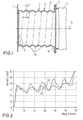
- Fig. 1 is 1 with the cross member of a front bumper and with 2 Designated longitudinal member, which up to that not shown for reasons of clarity Passenger cell of a motor vehicle extends.
- Between the cross member 1 and the side member 2 is made of sheet metal (with the DIN designation DC 04) existing impact damper 3 according to the invention arranged.
- the wall thickness of the Metal sheet is 1.5 mm in the illustrated embodiment.
- the impact damper 3 consists of a cup-shaped hollow body 4, the Bottom 5 at the same time as a flange plate for connecting the impact damper 3 with serves the cross member 1.
- the side 6 of the hollow body 4 facing away from the bottom 5 is bent outwards and is connected to a flange plate 7 of the longitudinal beam 2.
- the outer surface 8 of the tubular hollow body 4 is an outwardly curved and the bulge 10 enclosing the longitudinal axis 9 of the hollow body 4, a helical course with five turns enclosing the longitudinal axis 9 having.
- the pitch P corresponds to the helical bulge 10 their width B.
- the curve labeled a) gives the deformation force as a function of from the deformation path for the impact damper 3 according to the invention again while the curve designated b) shows the force curve for a corresponding impact damper with annular bulges.
- the figure is immediately apparent that by the helical configuration of the bulge 10 force peaks arising from the folding process are lower, so that results in a more uniform folding process than in the case of curve b).
- the invention is of course not based on the embodiment described above limited. So it does not necessarily have to be with the impact damper act an element separate from the side member of the corresponding vehicle, but the impact damper according to the invention can also in a partial area of the Be integrated longitudinal member. Furthermore, a separate impact damper with a Be connected to the side member, which has a corresponding integrated impact damper comprises, the two impact absorbers energy in different speed ranges absorb (e.g. the separate impact absorber is up to Speeds of 15 km / h and the impact absorber integrated in the side member effective up to speeds of 30 km / h).
- the impact absorber does not necessarily have to have a round cross section, but can also be a polygonal one, in particular a rectangular one have a square cross-section.
- the manufacture of such impact dampers can be done in a simple manner with the help of appropriately pre-embossed sheets, which are shaped to manufacture the damper and then reprimanded (e.g. welded) become.
Claims (5)
- Amortisseur de choc pour véhicules automobiles, comprenant un corps creux (4) tubulaire en métal qui, lors d'un choc, absorbe l'énergie par déformation plastique dans la direction de son axe longitudinal (9) et dont la surface périphérique, pour favoriser la formation de plis lors d'un choc, présente au moins un bombement (10) courbe dirigé vers l'extérieur qui entoure l'axe longitudinal (9) du corps creux (4), le corps creux (4) étant conçu de manière à ce que lors d'un choc la force soit appliquée dans la direction de l'axe longitudinal (9) du corps creux (4), le corps creux (4) ayant une forme de pot, le fond (5) du corps creux (4) étant conformé en bride, et la face du corps creux (4) éloignée du fond (5) étant cintrée en direction de l'extérieur de telle sorte que la zone de bord ainsi formée puisse être utilisée comme bride en tant que telle ou être liée à une plaque formant bride associée au corps creux (4), caractérisé en ce que le bombement (10) présente un tracé hélicoïdal avec au moins deux spires qui entourent l'axe longitudinal (9) du corps creux (4) et en ce que le pas (P) du bombement (10) hélicoïdal est < 2B, B représentant la largeur du bombement courbe.
- Amortisseur de chocs selon la revendication 1, caractérisé en ce que le pas (P) du bombement (10) courbe est < 1,5B.
- Amortisseur de chocs selon la revendication 1 ou 2, caractérisé en ce que le corps creux (4) tubulaire présente une section transversale circulaire, ovale ou polygonale.
- Amortisseur de chocs selon une des revendications 1 à 3, caractérisé en ce que le bombement (10) est interrompu par au moins trois zones en forme de cordons qui sont réparties de manière uniforme sur le pourtour du corps tubulaire et s'étendent dans la direction de l'axe longitudinal (9) du corps creux (4).
- Amortisseur de chocs selon une des revendications 1 à 4, caractérisé en ce que le corps creux (4) est en métal ou en aluminium.
Applications Claiming Priority (2)
| Application Number | Priority Date | Filing Date | Title |
|---|---|---|---|
| DE10000286 | 2000-01-07 | ||
| DE10000286A DE10000286A1 (de) | 2000-01-07 | 2000-01-07 | Aufpralldämpfer |
Publications (3)
| Publication Number | Publication Date |
|---|---|
| EP1114754A2 EP1114754A2 (fr) | 2001-07-11 |
| EP1114754A3 EP1114754A3 (fr) | 2002-08-07 |
| EP1114754B1 true EP1114754B1 (fr) | 2004-03-03 |
Family
ID=7626833
Family Applications (1)
| Application Number | Title | Priority Date | Filing Date |
|---|---|---|---|
| EP00126910A Expired - Lifetime EP1114754B1 (fr) | 2000-01-07 | 2000-12-08 | Amortisseur de choc |
Country Status (5)
| Country | Link |
|---|---|
| EP (1) | EP1114754B1 (fr) |
| DE (2) | DE10000286A1 (fr) |
| ES (1) | ES1048065Y (fr) |
| FR (1) | FR2803571B3 (fr) |
| IT (1) | IT249039Y1 (fr) |
Families Citing this family (8)
| Publication number | Priority date | Publication date | Assignee | Title |
|---|---|---|---|---|
| DE10128114B4 (de) * | 2001-03-28 | 2006-12-28 | Wagon Automotive Gmbh | Aufpralldämpfer |
| JPWO2005075254A1 (ja) * | 2004-02-10 | 2007-08-02 | 株式会社三五 | 車両の衝撃吸収装置 |
| DE102010027354A1 (de) * | 2010-07-16 | 2012-01-19 | Audi Ag | Tragstruktur einer Fahrzeugkarosserie |
| DE102012023651A1 (de) * | 2012-11-28 | 2014-05-28 | GM Global Technology Operations LLC (n. d. Gesetzen des Staates Delaware) | Dämpfeinheit, stossfangeinrichtung und kraftfahrzeug |
| FR3011520B1 (fr) | 2013-10-09 | 2016-12-16 | Autotech Eng A I E | Systeme amortisseur de choc pour vehicule automobile |
| WO2015163835A1 (fr) * | 2014-04-22 | 2015-10-29 | Coskunoz Metal Form Makina Endustri Ve Tic. A.S | Boîte-tampon |
| CN105083180A (zh) * | 2015-09-21 | 2015-11-25 | 常飞鹏 | 吸能式保险杠 |
| DE102020209190A1 (de) | 2020-07-22 | 2022-01-27 | Volkswagen Aktiengesellschaft | Crash Energieabsorber für ein Kraftfahrzeug |
Family Cites Families (10)
| Publication number | Priority date | Publication date | Assignee | Title |
|---|---|---|---|---|
| DE7327702U (de) * | 1973-07-28 | 1973-12-06 | Daimler-Benz Ag | Rohrförmiges Deformationsglied |
| US4312430A (en) * | 1979-12-12 | 1982-01-26 | Izumi Motor Co., Ltd. | Shock absorber |
| DE3045141C2 (de) * | 1980-11-29 | 1987-07-09 | Messerschmitt-Bölkow-Blohm GmbH, 8000 München | Sicherheitslenksäule für Kraftfahrzeuge |
| JPH02175452A (ja) | 1988-12-28 | 1990-07-06 | Isuzu Motors Ltd | 車両の衝撃吸収装置 |
| DE4211964C2 (de) * | 1992-04-09 | 1995-11-09 | Daimler Benz Ag | Als Wellrohr ausgebildeter Deformationskörper |
| DE4239460C2 (de) | 1992-11-24 | 1996-07-11 | Austria Metall | Stoßverzehrvorrichtung |
| JPH08276804A (ja) | 1995-04-05 | 1996-10-22 | Toyota Motor Corp | 自動車用衝突エネルギ吸収部材 |
| NO952840D0 (no) * | 1995-07-17 | 1995-07-17 | Norsk Hydro As | Stötfangersystem |
| DE19807158B4 (de) * | 1998-02-20 | 2009-03-12 | Adam Opel Ag | Pralldämpfer |
| DE19814842A1 (de) * | 1998-04-02 | 1999-10-07 | Wagon Automotive Gmbh | Aufpralldämpfer |
-
2000
- 2000-01-07 DE DE10000286A patent/DE10000286A1/de not_active Withdrawn
- 2000-11-27 IT IT2000RM000220U patent/IT249039Y1/it active
- 2000-12-08 DE DE50005509T patent/DE50005509D1/de not_active Expired - Fee Related
- 2000-12-08 EP EP00126910A patent/EP1114754B1/fr not_active Expired - Lifetime
-
2001
- 2001-01-05 ES ES200100026U patent/ES1048065Y/es not_active Expired - Fee Related
- 2001-01-05 FR FR0100107A patent/FR2803571B3/fr not_active Expired - Fee Related
Also Published As
| Publication number | Publication date |
|---|---|
| ES1048065U (es) | 2001-06-16 |
| EP1114754A3 (fr) | 2002-08-07 |
| IT249039Y1 (it) | 2003-03-25 |
| ES1048065Y (es) | 2001-11-01 |
| FR2803571B3 (fr) | 2001-11-16 |
| ITRM20000220V0 (it) | 2000-11-27 |
| DE50005509D1 (de) | 2004-04-08 |
| EP1114754A2 (fr) | 2001-07-11 |
| DE10000286A1 (de) | 2001-07-26 |
| ITRM20000220U1 (it) | 2002-05-27 |
| FR2803571A3 (fr) | 2001-07-13 |
Similar Documents
| Publication | Publication Date | Title |
|---|---|---|
| DE1630859C (fr) | ||
| DE60005468T2 (de) | Kraftfahrzeugstossstangenträger | |
| EP1245456B1 (fr) | Amortisseur de choc | |
| DE2254299C3 (fr) | ||
| DE2825460A1 (de) | Energieabsorber, insbesondere fuer motorfahrzeuge | |
| DE19959701A1 (de) | Vorrichtung zur Stoßenergieaufnahme bei Kraftfahrzeugen | |
| DE2610001A1 (de) | Puffereinrichtung fuer fahrzeuge | |
| DE102004008741A1 (de) | Stoßfängersystem | |
| EP0369520A2 (fr) | Elément de construction pour l'absorption d'énergie | |
| EP1533192A1 (fr) | Système de pare-choc | |
| DE19814842A1 (de) | Aufpralldämpfer | |
| EP1332081B1 (fr) | Jupe de colonne de direction d'automobile et procede de production de ladite jupe | |
| DE2254299B2 (de) | Rahmeneinheit eines kraftfahrzeuges zum absorbieren von aufprallenergie | |
| DE102011121038A1 (de) | Schutzeinrichtung für einenPersonenkraftwagen | |
| DE102005005107B4 (de) | Deformationselement | |
| EP1114754B1 (fr) | Amortisseur de choc | |
| DE10108279A1 (de) | Aufprallabsorbierende Struktur eines Fahrzeuges | |
| EP1541424B1 (fr) | Un élément d'absorption de choc en form profilé creux | |
| DE2222557A1 (de) | In fahrzeugen, insbesondere kraftfahrzeugen zur verwendung kommendes bauteil | |
| DE19829566B4 (de) | Aufpralldämpfer für Kraftfahrzeuge | |
| DE3038252A1 (de) | Stossabsorbierendes deformationsglied fuer kraftfahrzeuge, insbesondere personenkraftwagen | |
| EP1114753B1 (fr) | Amortisseur de choc | |
| EP0816179A2 (fr) | Absorbeur de chocs pour véhicules automobiles | |
| DE102018008894A1 (de) | Energieabsorptions-Baueinheit für einen Kraftwagen sowie Energieabsorptionselement und Verstärkungselement hierfür | |
| DE19704013C2 (de) | Sicherheitslenksäule |
Legal Events
| Date | Code | Title | Description |
|---|---|---|---|
| PUAI | Public reference made under article 153(3) epc to a published international application that has entered the european phase |
Free format text: ORIGINAL CODE: 0009012 |
|
| AK | Designated contracting states |
Kind code of ref document: A2 Designated state(s): AT BE CH CY DE DK ES FI FR GB GR IE IT LI LU MC NL PT SE TR |
|
| AX | Request for extension of the european patent |
Free format text: AL;LT;LV;MK;RO;SI |
|
| PUAL | Search report despatched |
Free format text: ORIGINAL CODE: 0009013 |
|
| AK | Designated contracting states |
Kind code of ref document: A3 Designated state(s): AT BE CH CY DE DK ES FI FR GB GR IE IT LI LU MC NL PT SE TR |
|
| AX | Request for extension of the european patent |
Free format text: AL;LT;LV;MK;RO;SI |
|
| 17P | Request for examination filed |
Effective date: 20020920 |
|
| 17Q | First examination report despatched |
Effective date: 20021216 |
|
| AKX | Designation fees paid |
Designated state(s): DE FR GB |
|
| GRAP | Despatch of communication of intention to grant a patent |
Free format text: ORIGINAL CODE: EPIDOSNIGR1 |
|
| GRAS | Grant fee paid |
Free format text: ORIGINAL CODE: EPIDOSNIGR3 |
|
| GRAA | (expected) grant |
Free format text: ORIGINAL CODE: 0009210 |
|
| AK | Designated contracting states |
Kind code of ref document: B1 Designated state(s): DE FR GB |
|
| REG | Reference to a national code |
Ref country code: GB Ref legal event code: FG4D Free format text: NOT ENGLISH |
|
| REG | Reference to a national code |
Ref country code: IE Ref legal event code: FG4D Free format text: GERMAN |
|
| REF | Corresponds to: |
Ref document number: 50005509 Country of ref document: DE Date of ref document: 20040408 Kind code of ref document: P |
|
| GBT | Gb: translation of ep patent filed (gb section 77(6)(a)/1977) |
Effective date: 20040517 |
|
| REG | Reference to a national code |
Ref country code: IE Ref legal event code: FD4D |
|
| ET | Fr: translation filed | ||
| PLBE | No opposition filed within time limit |
Free format text: ORIGINAL CODE: 0009261 |
|
| STAA | Information on the status of an ep patent application or granted ep patent |
Free format text: STATUS: NO OPPOSITION FILED WITHIN TIME LIMIT |
|
| 26N | No opposition filed |
Effective date: 20041206 |
|
| PGFP | Annual fee paid to national office [announced via postgrant information from national office to epo] |
Ref country code: FR Payment date: 20051219 Year of fee payment: 6 |
|
| PGFP | Annual fee paid to national office [announced via postgrant information from national office to epo] |
Ref country code: GB Payment date: 20051222 Year of fee payment: 6 |
|
| PGFP | Annual fee paid to national office [announced via postgrant information from national office to epo] |
Ref country code: DE Payment date: 20061222 Year of fee payment: 7 |
|
| GBPC | Gb: european patent ceased through non-payment of renewal fee |
Effective date: 20061208 |
|
| REG | Reference to a national code |
Ref country code: FR Ref legal event code: ST Effective date: 20070831 |
|
| PG25 | Lapsed in a contracting state [announced via postgrant information from national office to epo] |
Ref country code: GB Free format text: LAPSE BECAUSE OF NON-PAYMENT OF DUE FEES Effective date: 20061208 |
|
| PG25 | Lapsed in a contracting state [announced via postgrant information from national office to epo] |
Ref country code: FR Free format text: LAPSE BECAUSE OF NON-PAYMENT OF DUE FEES Effective date: 20070102 |
|
| PG25 | Lapsed in a contracting state [announced via postgrant information from national office to epo] |
Ref country code: DE Free format text: LAPSE BECAUSE OF NON-PAYMENT OF DUE FEES Effective date: 20080701 |