EP1114754B1 - Shock absorber - Google Patents
Shock absorber Download PDFInfo
- Publication number
- EP1114754B1 EP1114754B1 EP00126910A EP00126910A EP1114754B1 EP 1114754 B1 EP1114754 B1 EP 1114754B1 EP 00126910 A EP00126910 A EP 00126910A EP 00126910 A EP00126910 A EP 00126910A EP 1114754 B1 EP1114754 B1 EP 1114754B1
- Authority
- EP
- European Patent Office
- Prior art keywords
- hollow body
- impact
- bulge
- longitudinal axis
- absorbing device
- Prior art date
- Legal status (The legal status is an assumption and is not a legal conclusion. Google has not performed a legal analysis and makes no representation as to the accuracy of the status listed.)
- Expired - Lifetime
Links
Images
Classifications
-
- B—PERFORMING OPERATIONS; TRANSPORTING
- B60—VEHICLES IN GENERAL
- B60R—VEHICLES, VEHICLE FITTINGS, OR VEHICLE PARTS, NOT OTHERWISE PROVIDED FOR
- B60R19/00—Wheel guards; Radiator guards, e.g. grilles; Obstruction removers; Fittings damping bouncing force in collisions
- B60R19/02—Bumpers, i.e. impact receiving or absorbing members for protecting vehicles or fending off blows from other vehicles or objects
- B60R19/24—Arrangements for mounting bumpers on vehicles
- B60R19/26—Arrangements for mounting bumpers on vehicles comprising yieldable mounting means
- B60R19/34—Arrangements for mounting bumpers on vehicles comprising yieldable mounting means destroyed upon impact, e.g. one-shot type
-
- F—MECHANICAL ENGINEERING; LIGHTING; HEATING; WEAPONS; BLASTING
- F16—ENGINEERING ELEMENTS AND UNITS; GENERAL MEASURES FOR PRODUCING AND MAINTAINING EFFECTIVE FUNCTIONING OF MACHINES OR INSTALLATIONS; THERMAL INSULATION IN GENERAL
- F16F—SPRINGS; SHOCK-ABSORBERS; MEANS FOR DAMPING VIBRATION
- F16F7/00—Vibration-dampers; Shock-absorbers
- F16F7/12—Vibration-dampers; Shock-absorbers using plastic deformation of members
Definitions
- the invention relates to an impact damper for motor vehicles by plastic Deformation in the event of an impact absorbs energy with the characteristics of the generic term of claim 1.
- the arranged on the bumper-side cross members longitudinal members, which in turn are connected to the passenger compartment in such a way that they through absorb the energy released by the deformation.
- Such a deformation can be achieved on the one hand by bending the side members, the bending moment resulting from the impact to a deformation of the side member lead and the deformation points determined by the choice of cross-sections become.
- the longitudinal beams can also be deformed in the longitudinal direction be brought about by beads.
- Impact absorbers of the type mentioned above in which essentially only Side members themselves form the respective shock absorber are relatively expensive to manufacture. Since the impact absorbers also operate at low speeds (e.g. at 10 km / h) to absorb an impact, the side members have to frequently replaced after collisions, which is extremely time consuming and is expensive.
- an impact damper which consists of a relatively short There is a hollow body and between the bumper-side cross member and the associated side member of the corresponding vehicle is used.
- Hollow body is z.
- This impact damper is that the compression of the tubular hollow body does not lead to the occurrence of precisely defined ring folds, so that an exact speed-dependent Adaptation of the impact behavior of the respective motor vehicle is not possible with such shock absorbers. It also has one Impact absorber an undesirably high first load peak and not ideal axial load transfer due to the bending collapse behavior that then occurs a greatly reduced energy consumption.
- the impact damper known from DE 198 14 842 A1, of which the invention goes out, has on the face connecting means for connection to adjacent body parts of the motor vehicle in order to apply force in the event of an impact (connecting means for the cross member of a front bumper on the one hand and the Longitudinal member of the passenger compartment on the other hand).
- These connecting means are particularly inexpensive in that the hollow body is cup-shaped and the bottom of the Hollow body is designed as a flange, the side of the Hollow body is bent outwards in such a way that the edge region formed thereby can also be used as a flange or with a flange plate assigned to the hollow body is connectable.
- the cup-shaped production of the hollow body can be done easily Achieve way by deep drawing a sheet, taking after deep drawing by another molding process, preferably an internal high pressure process, the predetermined bulges can be introduced into the hollow body.
- the invention is based on the object Impact absorber to be installed in the body, in which there are wrinkles force of the tubular hollow body is as uniform as possible results in lower force peaks than with the known impact absorbers, without resulting in a reduction in energy consumption.
- the invention is essentially based on the idea of defined wrinkling provided curved bulges not as a closed ring-shaped, but as helical areas with a relatively small average pitch angle embody. At least two should be the longitudinal axis of the hollow body enclosing turns can be provided. The slope of each helical bulge should be at most twice the width (B) of the Bulge correspond. The slope should preferably be ⁇ 1.5 B.
- the helical configuration of the bulge gives a more uniform one Wrinkle pattern, i.e. the force peaks that occur during the folding process have a lower amplitude than that of corresponding annular bulges provided shock absorbers.
- the impact dampers according to the invention are used also with non-axial load application a higher energy consumption than with comparable impact absorbers with ring-shaped bulges. It played practically no matter whether the impact damper in relation to the introduction of force was positioned that the pitch angle is reduced or increased.
- the tubular hollow body of the impact damper can be a circular, oval or also have a polygonal cross section.
- the bulge by at least three arranged evenly distributed over the circumference of the tubular body and web-shaped extending in the direction of the longitudinal axis of the hollow body Areas interrupted.
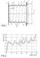
- Fig. 1 is 1 with the cross member of a front bumper and with 2 Designated longitudinal member, which up to that not shown for reasons of clarity Passenger cell of a motor vehicle extends.
- Between the cross member 1 and the side member 2 is made of sheet metal (with the DIN designation DC 04) existing impact damper 3 according to the invention arranged.
- the wall thickness of the Metal sheet is 1.5 mm in the illustrated embodiment.
- the impact damper 3 consists of a cup-shaped hollow body 4, the Bottom 5 at the same time as a flange plate for connecting the impact damper 3 with serves the cross member 1.
- the side 6 of the hollow body 4 facing away from the bottom 5 is bent outwards and is connected to a flange plate 7 of the longitudinal beam 2.
- the outer surface 8 of the tubular hollow body 4 is an outwardly curved and the bulge 10 enclosing the longitudinal axis 9 of the hollow body 4, a helical course with five turns enclosing the longitudinal axis 9 having.
- the pitch P corresponds to the helical bulge 10 their width B.
- the curve labeled a) gives the deformation force as a function of from the deformation path for the impact damper 3 according to the invention again while the curve designated b) shows the force curve for a corresponding impact damper with annular bulges.
- the figure is immediately apparent that by the helical configuration of the bulge 10 force peaks arising from the folding process are lower, so that results in a more uniform folding process than in the case of curve b).
- the invention is of course not based on the embodiment described above limited. So it does not necessarily have to be with the impact damper act an element separate from the side member of the corresponding vehicle, but the impact damper according to the invention can also in a partial area of the Be integrated longitudinal member. Furthermore, a separate impact damper with a Be connected to the side member, which has a corresponding integrated impact damper comprises, the two impact absorbers energy in different speed ranges absorb (e.g. the separate impact absorber is up to Speeds of 15 km / h and the impact absorber integrated in the side member effective up to speeds of 30 km / h).
- the impact absorber does not necessarily have to have a round cross section, but can also be a polygonal one, in particular a rectangular one have a square cross-section.
- the manufacture of such impact dampers can be done in a simple manner with the help of appropriately pre-embossed sheets, which are shaped to manufacture the damper and then reprimanded (e.g. welded) become.
Landscapes
- Engineering & Computer Science (AREA)
- General Engineering & Computer Science (AREA)
- Mechanical Engineering (AREA)
- Vibration Dampers (AREA)
Description
Die Erfindung betrifft einen Aufpralldämpfer für Kraftfahrzeuge, der durch plastische
Deformation bei einem Aufprall Energie aufnimmt, mit den Merkmalen des Oberbegriffs
des Anspruchs 1.The invention relates to an impact damper for motor vehicles by plastic
Deformation in the event of an impact absorbs energy with the characteristics of the generic term
of
Zum Schutz der Insassen eines Fahrzeuges bei einem Front- oder Heckaufprall ist es bekannt, die an den stoßstangenseitigen Querträgern angeordneten Längsträger, die ihrerseits mit der Fahrgastzelle verbunden sind, derart auszugestalten, daß sie die durch den Aufprall freiwerdende Energie durch Verformung aufnehmen. Eine derartige Verformung kann einerseits dadurch erreicht werden, daß die Längsträger gebogen sind, wobei das beim Aufprall entstehende Biegemoment zu einer Verformung des Längsträgers führen und die Verformungsstellen durch die Wahl der Querschnitte bestimmt werden. Andererseits kann eine Verformung der Längsträger in Längsrichtung auch durch Sicken herbeigeführt werden.It is to protect the occupants of a vehicle in a front or rear impact known, the arranged on the bumper-side cross members longitudinal members, which in turn are connected to the passenger compartment in such a way that they through absorb the energy released by the deformation. Such a deformation can be achieved on the one hand by bending the side members, the bending moment resulting from the impact to a deformation of the side member lead and the deformation points determined by the choice of cross-sections become. On the other hand, the longitudinal beams can also be deformed in the longitudinal direction be brought about by beads.
Aufpralldämpfer der vorstehend erwähnten Art, bei denen im wesentlichen nur die Längsträger selbst den jeweiligen Aufpralldämpfer bilden, sind relativ aufwendig herzustellen. Da die Aufpralldämpfer auch im niedrigen Geschwindigkeitsbereich (z. B. bei 10 km/h) einen Aufprall abfangen müssen, müssen die Längsträger entsprechend häufig nach Zusammenstößen ersetzt werden, was außerordentlich zeitaufwendig und teuer ist.Impact absorbers of the type mentioned above, in which essentially only Side members themselves form the respective shock absorber are relatively expensive to manufacture. Since the impact absorbers also operate at low speeds (e.g. at 10 km / h) to absorb an impact, the side members have to frequently replaced after collisions, which is extremely time consuming and is expensive.
Aus der DE 42 39 460 A1 ist ein Aufpralldämpfer bekannt, der aus einem relativ kurzen Hohlkörper besteht und zwischen dem stoßstangenseitigen Querträger und dem dazugehörigen Längsträger des entsprechenden Fahrzeuges eingesetzt wird. Bei dem Hohlkörper handelt es sich z. B. um ein Rohrstück welches derart ausgestaltet ist, daß es bei einem Aufprall des Fahrzeuges gestaucht wird und dabei in Längsrichtung mehrere Ringfalten bildet.From DE 42 39 460 A1 an impact damper is known, which consists of a relatively short There is a hollow body and between the bumper-side cross member and the associated side member of the corresponding vehicle is used. In which Hollow body is z. B. a piece of pipe which is designed such that it is compressed in the event of a collision of the vehicle and several in the longitudinal direction Forms ring folds.
Nachteilig ist bei diesem Aufpralldämpfer, daß die Stauchung des rohrförmigen Hohlkörpers nicht zum Auftreten genau definierter Ringfalten führt, so daß eine genaue geschwindigkeitsabhängige Anpassung des Aufprallverhaltens des jeweiligen Kraftfahrzeuges mit derartigen Aufpralldämpfern nicht möglich ist. Außerdem besitzt ein derartiger Aufpralldämpfer eine unerwünscht hohe erste Traglastspitze und bei nicht idealer axialer Lasteinleitung aufgrund des dann auftretenden Biegekollapsverhaltens eine stark verminderte Energieaufnahme.The disadvantage of this impact damper is that the compression of the tubular hollow body does not lead to the occurrence of precisely defined ring folds, so that an exact speed-dependent Adaptation of the impact behavior of the respective motor vehicle is not possible with such shock absorbers. It also has one Impact absorber an undesirably high first load peak and not ideal axial load transfer due to the bending collapse behavior that then occurs a greatly reduced energy consumption.
Aus der DE 42 39 460 A1 sowie aus der DE 198 14 842 A1 ist ferner bekannt, zur sicheren Bildung von symmetrischer Ringfalten im Kollisionsfalle das Rohrstück in Längsrichtung vorzustauchen, so daß es in seiner Ausgangslage bereits leicht ausgebeult oder ausgebaucht ist. Versuche haben gezeigt, daß bei einem derartigen Aufpralldämpfer auch die Energieaufnahme bei nicht idealer Lasteinleitung (schräger Aufprall) besser ist als bei nicht vorgestauchten rohrförmigen Aufpralldämpfern. Allerdings ergibt sich bei dem Faltungsvorgang ein oszillierender Kraftverlauf mit relativ ausgeprägten Extremwerten.From DE 42 39 460 A1 and from DE 198 14 842 A1 is also known for safe Formation of symmetrical ring folds in the event of a collision To advance in the longitudinal direction so that it is already slightly bulged in its initial position or bulged. Tests have shown that with such an impact damper also the energy consumption when the load is not ideal (inclined Impact) is better than with non-pre-compressed tubular impact dampers. Indeed the folding process results in an oscillating force curve with relative pronounced extreme values.
Der aus der DE 198 14 842 A1 bekannte Aufpralldämpfer, von dem die Erfindung ausgeht, weist stirnseitig Verbindungsmittel zur Verbindung mit angrenzenden Karosserieteilen des Kraftfahrzeugs zwecks Krafteinleitung bei einem Aufprall auf (Verbindungsmittel für den Querträger einer vorderseitigen Stoßstange einerseits und den Längsträger der Fahrgastzelle andererseits). Besonders kostengünstig sind diese Verbindungsmittel dadurch realisiert, daß der Hohlkörper topfförmig und der Boden des Hohlkörpers als Flansch ausgebildet ist, wobei die dem Boden abgewandte Seite des Hohlkörpers derart nach außen gebogen ist, daß der dadurch gebildete Randbereich auch als Flansch verwendbar oder mit einer dem Hohlkörper zugeordneten Flanschplatte verbindbar ist. Die topfförmige Herstellung des Hohlkörpers läßt sich auf einfache Weise durch Tiefziehen eines Bleches erreichen, wobei nach dem Tiefziehen durch ein weiteres Formverfahren, vorzugsweise ein Innen-Hochdruckverfahren, die vorgegebenen Ausbuchtungen in den Hohlkörper eingebracht werden können.The impact damper known from DE 198 14 842 A1, of which the invention goes out, has on the face connecting means for connection to adjacent body parts of the motor vehicle in order to apply force in the event of an impact (connecting means for the cross member of a front bumper on the one hand and the Longitudinal member of the passenger compartment on the other hand). These connecting means are particularly inexpensive in that the hollow body is cup-shaped and the bottom of the Hollow body is designed as a flange, the side of the Hollow body is bent outwards in such a way that the edge region formed thereby can also be used as a flange or with a flange plate assigned to the hollow body is connectable. The cup-shaped production of the hollow body can be done easily Achieve way by deep drawing a sheet, taking after deep drawing by another molding process, preferably an internal high pressure process, the predetermined bulges can be introduced into the hollow body.
Bei einem Aufpralldämpfer für eine Kraftfahrzeug-Lenksäule, der gleichsam als Zwischenstück
der insgesamt rohrförmigen Lenksäule eingesetzt wird, ist es bekannt, die
Mantelfläche dieses Einsatzstückes der Lenksäule mit einer nach außen gewölbten und
die Längsachse dieses Hohlkörpers umschließenden Ausbuchtung zu versehen, die
schraubenlinienförmig mit mindestens zwei die Längsachse des Hohlkörpers umschließenden
Windungen verläuft (FR 2 238 869 A1). Die Besonderheiten von Aufpralldämpfem
in Lenksäulen lassen eine Übertragung auf Aufpralldämpfer im Karosseriebau,
insbesondere für Längsträger etc. nicht ohne weiteres zu.In an impact damper for a motor vehicle steering column, as it were as an intermediate piece
of the total tubular steering column is used, it is known that
Shell surface of this insert of the steering column with an outwardly curved and
to provide the bulge enclosing the longitudinal axis of this hollow body, the
helical with at least two enclosing the longitudinal axis of the hollow body
Turns (
Ausgehend von der DE 198 14 842 A1 liegt der Erfindung die Aufgabe zugrunde, einen Aufpralldämpfer für den Karosserieeinbau anzugeben, bei dem sich bei der Faltenbildung des rohrförmigen Hohlkörpers ein möglichst gleichmäßiger Kraftverlauf ergibt und somit geringere Kraftspitzen auftreten als bei den bekannten Aufpralldämpfern, ohne daß es dadurch zu einer Verminderung der Energieaufnahme kommt.Starting from DE 198 14 842 A1, the invention is based on the object Impact absorber to be installed in the body, in which there are wrinkles force of the tubular hollow body is as uniform as possible results in lower force peaks than with the known impact absorbers, without resulting in a reduction in energy consumption.
Diese Aufgabe wird erfindungsgemäß durch die Merkmale des Anspruchs 1 gelöst.
Weitere, besonders vorteilhafte Ausgestaltungen der Erfindung offenbaren die Unteransprüche.This object is achieved according to the invention by the features of
Die Erfindung beruht im wesentlichen auf dem Gedanken, die zur definierten Faltenbildung vorgesehenen gewölbten Ausbuchtungen nicht als geschlossene ringförmige, sondern als schraubenförmige Bereiche mit einem relativ geringen mittleren Steigungswinkel auszugestalten. Dabei sollten mindestens zwei die Längsachse des Hohlkörpers umschließende Windungen vorgesehen sein. Die Steigung der jeweiligen schraubenförmigen Ausbuchtung sollte dabei maximal der doppelten Breite (B) der Ausbuchtung entsprechen. Vorzugsweise sollte die Steigung < 1,5 B sein.The invention is essentially based on the idea of defined wrinkling provided curved bulges not as a closed ring-shaped, but as helical areas with a relatively small average pitch angle embody. At least two should be the longitudinal axis of the hollow body enclosing turns can be provided. The slope of each helical bulge should be at most twice the width (B) of the Bulge correspond. The slope should preferably be <1.5 B.
Durch die schraubenförmige Ausgestaltung der Ausbuchtung erhält man ein gleichmäßigeres Faltenbild, d.h., die bei dem Faltungsvorgang auftretenden Kraftspitzen weisen eine geringere Amplitude auf als die bei entsprechenden ringförmigen Ausbuchtungen versehenen Aufpralldämpfern.The helical configuration of the bulge gives a more uniform one Wrinkle pattern, i.e. the force peaks that occur during the folding process have a lower amplitude than that of corresponding annular bulges provided shock absorbers.
Überraschenderweise ergibt sich bei Verwendung der erfindungsgemäßen Aufpralldämpfer ebenfalls bei nichtaxialer Lasteinleitung eine höhere Energieaufnahme als bei vergleichbaren Aufpralldämpfern mit ringförmigen Ausbuchtungen. Dabei spielte es praktisch keine Rolle, ob der Aufpralldämpfer in bezug auf die Krafteinleitung derart positioniert war, daß der Steigungswinkel reduziert oder erhöht wird.Surprisingly, the impact dampers according to the invention are used also with non-axial load application a higher energy consumption than with comparable impact absorbers with ring-shaped bulges. It played practically no matter whether the impact damper in relation to the introduction of force was positioned that the pitch angle is reduced or increased.
Als Material für den Hohlkörper hat sich als besonders vorteilhaft Stahlblech oder Aluminium mit einer ausreichenden Dehnung bewährt. Steel sheet or has proven to be particularly advantageous as the material for the hollow body Proven aluminum with sufficient elongation.
Der rohrförmige Hohlkörper des Aufpralldämpfers kann einen kreisförmigen, ovalen oder auch mehreckigen Querschnitt aufweisen.The tubular hollow body of the impact damper can be a circular, oval or also have a polygonal cross section.
Bei einer weiteren vorteilhaften Ausführungsform der Erfindung ist die Ausbuchtung durch mindestens drei gleichmäßig über den Umfang des Rohrkörpers verteilt angeordnete und sich in Richtung der Längsachse des Hohlkörpers erstreckende stegförmige Bereiche unterbrochen. Durch diese Maßnahme kann das gesamte Kraftniveau des sich bei einem Aufprall ergebenden Kraft-Weg-Diagrammes und damit auch die Energieabsorption des Aufpralldämpfers weiter erhöht werden.In a further advantageous embodiment of the invention, the bulge by at least three arranged evenly distributed over the circumference of the tubular body and web-shaped extending in the direction of the longitudinal axis of the hollow body Areas interrupted. Through this measure, the entire power level of the the force-displacement diagram resulting from an impact and thus also the Energy absorption of the impact absorber can be increased further.
Weitere Einzelheiten und Vorteile der Erfindung ergeben sich aus den folgenden anhand von Figuren erläuterten Ausführungsbeispielen. Es zeigen:
- Fig. 1
- den Längsschnitt durch ein Ausführungsbeispiel eines zwischen dem Querträger und dem Längsträger eines Kraftfahrzeuges angeordneten erfindungsgemäßen Aufpralldämpfers und
- Fig. 2
- ein Kraft-Weg-Diagramm des in Fig. 1 dargestellten erfindungsgemäßen Aufpralldämpfers bei einem Aufprall in axialer Richtung (Kurve a)) sowie eines Aufpralldämpfers lediglich mit ringförmigen Ausbuchtungen (Kurve b));
- Fig. 1
- the longitudinal section through an embodiment of an impact damper according to the invention arranged between the cross member and the longitudinal member of a motor vehicle and
- Fig. 2
- a force-displacement diagram of the impact damper according to the invention shown in Figure 1 in the event of an impact in the axial direction (curve a)) and an impact damper only with annular bulges (curve b));
In Fig. 1 ist mit 1 der Querträger eines vorderseitigen Stoßfängers und mit 2 ein
Längsträger bezeichnet, der sich bis zu der aus Übersichtlichkeitsgründen nicht dargestellten
Fahrgastzelle eines Kraftfahrzeuges erstreckt. Zwischen dem Querträger 1 und
dem Längsträger 2 ist ein aus einem Metallblech (mit der DIN-Bezeichnung DC 04)
bestehender erfindungsgemäßer Aufpralldämpfer 3 angeordnet. Die Wandstärke des
Metallbleches beträgt bei dem dargestellten Ausführungsbeispiel 1,5 mm.In Fig. 1 is 1 with the cross member of a front bumper and with 2
Designated longitudinal member, which up to that not shown for reasons of clarity
Passenger cell of a motor vehicle extends. Between the
Der Aufpralldämpfer 3 besteht aus einem topfförmig ausgebildeten Hohlkörper 4, dessen
Boden 5 gleichzeitig als Flanschplatte zur Verbindung des Aufpralldämpfers 3 mit
dem Querträger 1 dient. Die dem Boden 5 abgewandte Seite 6 des Hohlkörpers 4 ist
nach außen gebogen und ist mit einer Flanschplatte 7 des Längsträgers 2 verbunden. The impact damper 3 consists of a cup-shaped hollow body 4, the
In die Mantelfläche 8 des rohrförmigen Hohlkörpers 4 ist eine nach außen gewölbte
und die Längsachse 9 des Hohlkörpers 4 umschließende Ausbuchtung 10 eingebracht,
die einen schraubenförmigen Verlauf mit fünf die Längsachse 9 umschließenden Windungen
aufweist. Die Steigung P der schraubenförmigen Ausbuchtung 10 entspricht
ihrer Breite B.In the outer surface 8 of the tubular hollow body 4 is an outwardly curved
and the
In Fig. 2 gibt die mit a) bezeichnete Kurve die Deformationskraft in Abhängigkeit
vom Verformungsweg für den erfindungsgemäßen Aufpralldämpfer 3 wieder, während
die mit b) bezeichnete Kurve den Kraftverlauf für einen entsprechenden Aufpralldämpfer
mit ringförmigen Ausbuchtungen zeigt. Der Fig. ist unmittelbar entnehmbar,
daß durch die schraubenförmige Ausgestaltung der Ausbuchtung 10 die
durch den Faltungsvorgang entstehenden Kraftspitzen geringer werden, so daß sich
ein gleichmäßigerer Faltungsverlauf als im Falle der Kurve b) ergibt.In Fig. 2, the curve labeled a) gives the deformation force as a function of
from the deformation path for the impact damper 3 according to the invention again while
the curve designated b) shows the force curve for a corresponding impact damper
with annular bulges. The figure is immediately apparent
that by the helical configuration of the
Die Erfindung ist selbstverständlich nicht auf das vorstehend beschriebene Ausführungsbeispiel beschränkt. So muß es sich bei dem Aufpralldämpfer nicht zwingend um ein von dem Längsträger des entsprechenden Fahrzeuges separates Element handeln, sondern der erfindungsgemäße Aufpralldämpfer kann auch in einen Teilbereich des Längsträgers integriert sein. Ferner kann auch ein separater Aufpralldämpfer mit einem Längsträger verbunden sein, welcher einen entsprechenden integrierten Aufpralldämpfer umfaßt, wobei die beiden Aufpralldämpfer Energie in unterschiedlichen Geschwindigkeitsbereichen absorbieren (z. B. ist der separate Aufpralldämpfer bis zu Geschwindigkeiten von 15 km/h und der in den Längsträger integrierte Aufpralldämpfer bis zu Geschwindigkeiten von 30 km/h wirksam).The invention is of course not based on the embodiment described above limited. So it does not necessarily have to be with the impact damper act an element separate from the side member of the corresponding vehicle, but the impact damper according to the invention can also in a partial area of the Be integrated longitudinal member. Furthermore, a separate impact damper with a Be connected to the side member, which has a corresponding integrated impact damper comprises, the two impact absorbers energy in different speed ranges absorb (e.g. the separate impact absorber is up to Speeds of 15 km / h and the impact absorber integrated in the side member effective up to speeds of 30 km / h).
Schließlich muß der Aufpralldämpfer nicht zwingend einen runden Querschnitt besitzen, sondern kann auch einen mehreckigen, insbesondere einen rechteckigen oder quadratischen Querschnitt aufweisen. Die Herstellung derartiger Aufpralldämpfer kann dabei auf einfache Weise mit Hilfe von entsprechend vorgeprägten Blechen erfolgen, die zur Fertigung der Dämpfer geformt und dann gerügt (z. B. verschweißt) werden.Finally, the impact absorber does not necessarily have to have a round cross section, but can also be a polygonal one, in particular a rectangular one have a square cross-section. The manufacture of such impact dampers can be done in a simple manner with the help of appropriately pre-embossed sheets, which are shaped to manufacture the damper and then reprimanded (e.g. welded) become.
Claims (5)
- An impact absorbing device for motor vehicles,
comprising a tubular hollow body (4) consisting of metal, which absorbs energy on an impact by plastic deformation in the direction of its longitudinal axis (9) and the curved surface of which comprises at least one outwardly curved bulge (10) which surrounds the longitudinal axis (9) of the hollow body (4) in order to improve crumple zone formation on an impact,
wherein the tubular hollow body (4) is designed for the introduction of force in the direction of the longitudinal axis (9) of the hollow body (4) on an impact,
wherein for this purpose the hollow body (4) is of pot-shaped construction and the base (5) of the hollow body (4) is formed as a flange, and moreover the face (6) of the hollow body (4) facing away from the base (5) is bent outwards so that the edge region which is thereby formed can either itself be used as a flange or can be attached to a flange plate associated with the hollow body (4),
characterised in that
the bulge (10) extends in the form of a helix and comprises at least two turns which surround the longitudinal axis (9) of the hollow body (4), and that the pitch (P) of the helical bulge (10) is < 2B, where B denotes the width of the curved bulge. - An impact absorbing device according to claim 1, characterised in that the pitch (P) of the curved bulge (10) is < 1.5B.
- An impact absorbing device according to claim 1 or 2, characterised in that the tubular hollow body (4) has a circular, oval or polygonal cross-section.
- An impact absorbing device according to any one of claims 1 to 3, characterised in that the bulge (10) is interrupted by at least three rib-like regions which are uniformly distributed over the periphery of the tubular body and which extend in the direction of the longitudinal axis (9) of the hollow body (4).
- An impact absorbing device according to any one of claims 1 to 4, characterised in that the hollow body (4) consists of steel or aluminium.
Applications Claiming Priority (2)
| Application Number | Priority Date | Filing Date | Title |
|---|---|---|---|
| DE10000286A DE10000286A1 (en) | 2000-01-07 | 2000-01-07 | Impact absorber |
| DE10000286 | 2000-01-07 |
Publications (3)
| Publication Number | Publication Date |
|---|---|
| EP1114754A2 EP1114754A2 (en) | 2001-07-11 |
| EP1114754A3 EP1114754A3 (en) | 2002-08-07 |
| EP1114754B1 true EP1114754B1 (en) | 2004-03-03 |
Family
ID=7626833
Family Applications (1)
| Application Number | Title | Priority Date | Filing Date |
|---|---|---|---|
| EP00126910A Expired - Lifetime EP1114754B1 (en) | 2000-01-07 | 2000-12-08 | Shock absorber |
Country Status (5)
| Country | Link |
|---|---|
| EP (1) | EP1114754B1 (en) |
| DE (2) | DE10000286A1 (en) |
| ES (1) | ES1048065Y (en) |
| FR (1) | FR2803571B3 (en) |
| IT (1) | IT249039Y1 (en) |
Families Citing this family (8)
| Publication number | Priority date | Publication date | Assignee | Title |
|---|---|---|---|---|
| DE10128114B4 (en) * | 2001-03-28 | 2006-12-28 | Wagon Automotive Gmbh | impact attenuator |
| US20070181393A1 (en) * | 2004-02-10 | 2007-08-09 | Sango Co., Ltd. | Impact absorbing device of vehicle |
| DE102010027354A1 (en) * | 2010-07-16 | 2012-01-19 | Audi Ag | Supporting structure for vehicle body, has two longitudinal support units, where latter longitudinal support unit is coupled to coupling unit |
| DE102012023651A1 (en) * | 2012-11-28 | 2014-05-28 | GM Global Technology Operations LLC (n. d. Gesetzen des Staates Delaware) | Damping unit for shock absorber of motor car, has outwardly delimiting shroud that comprises cavity transverse to longitudinal direction and partially weakening unit that surrounds outwardly delimiting shroud |
| FR3011520B1 (en) | 2013-10-09 | 2016-12-16 | Autotech Eng A I E | SHOCK ABSORBER SYSTEM FOR MOTOR VEHICLE |
| WO2015163835A1 (en) * | 2014-04-22 | 2015-10-29 | Coskunoz Metal Form Makina Endustri Ve Tic. A.S | A crash box |
| CN105083180A (en) * | 2015-09-21 | 2015-11-25 | 常飞鹏 | Energy absorbing type bumper |
| DE102020209190A1 (en) | 2020-07-22 | 2022-01-27 | Volkswagen Aktiengesellschaft | Crash energy absorber for a motor vehicle |
Family Cites Families (10)
| Publication number | Priority date | Publication date | Assignee | Title |
|---|---|---|---|---|
| DE7327702U (en) * | 1973-07-28 | 1973-12-06 | Daimler-Benz Ag | Tubular deformation member |
| US4312430A (en) * | 1979-12-12 | 1982-01-26 | Izumi Motor Co., Ltd. | Shock absorber |
| DE3045141C2 (en) * | 1980-11-29 | 1987-07-09 | Messerschmitt-Bölkow-Blohm GmbH, 8000 München | Safety steering column for motor vehicles |
| JPH02175452A (en) | 1988-12-28 | 1990-07-06 | Isuzu Motors Ltd | Shock absorber of vehicle |
| DE4211964C2 (en) * | 1992-04-09 | 1995-11-09 | Daimler Benz Ag | Deformation body designed as a corrugated tube |
| DE4239460C2 (en) | 1992-11-24 | 1996-07-11 | Austria Metall | Shock absorbing device |
| JPH08276804A (en) | 1995-04-05 | 1996-10-22 | Toyota Motor Corp | Collision energy absorbing member for automobile |
| NO952840D0 (en) * | 1995-07-17 | 1995-07-17 | Norsk Hydro As | Stötfangersystem |
| DE19807158B4 (en) * | 1998-02-20 | 2009-03-12 | Adam Opel Ag | impact absorbers |
| DE19814842A1 (en) | 1998-04-02 | 1999-10-07 | Wagon Automotive Gmbh | Collision impact damping device for motor vehicle |
-
2000
- 2000-01-07 DE DE10000286A patent/DE10000286A1/en not_active Withdrawn
- 2000-11-27 IT IT2000RM000220U patent/IT249039Y1/en active
- 2000-12-08 DE DE50005509T patent/DE50005509D1/en not_active Expired - Fee Related
- 2000-12-08 EP EP00126910A patent/EP1114754B1/en not_active Expired - Lifetime
-
2001
- 2001-01-05 ES ES200100026U patent/ES1048065Y/en not_active Expired - Fee Related
- 2001-01-05 FR FR0100107A patent/FR2803571B3/en not_active Expired - Fee Related
Also Published As
| Publication number | Publication date |
|---|---|
| DE50005509D1 (en) | 2004-04-08 |
| IT249039Y1 (en) | 2003-03-25 |
| EP1114754A3 (en) | 2002-08-07 |
| FR2803571A3 (en) | 2001-07-13 |
| DE10000286A1 (en) | 2001-07-26 |
| ITRM20000220U1 (en) | 2002-05-27 |
| ITRM20000220V0 (en) | 2000-11-27 |
| ES1048065U (en) | 2001-06-16 |
| EP1114754A2 (en) | 2001-07-11 |
| ES1048065Y (en) | 2001-11-01 |
| FR2803571B3 (en) | 2001-11-16 |
Similar Documents
| Publication | Publication Date | Title |
|---|---|---|
| DE1630859C (en) | ||
| DE60005468T2 (en) | MOTOR VEHICLE BUMPER SUPPORT | |
| EP1245456B1 (en) | Impact absorber | |
| DE2254299C3 (en) | ||
| DE2825460A1 (en) | ENERGY ABSORBERS, IN PARTICULAR FOR MOTOR VEHICLES | |
| DE19959701A1 (en) | Device for impact energy absorption in road vehicle in event of collision involves box profile in plate structure fixed to at least one bodywork part | |
| DE102004008741A1 (en) | bumper system | |
| DE3838595A1 (en) | COMPONENT FOR ABSORPTION OF ENERGY | |
| EP1533192A1 (en) | Bumper system | |
| DE19814842A1 (en) | Collision impact damping device for motor vehicle | |
| EP1332081B1 (en) | Column tube of a steering column of a motor vehicle and a method for producing the column tube | |
| DE2254299B2 (en) | FRAME UNIT OF A MOTOR VEHICLE FOR ABSORBING IMPACT ENERGY | |
| DE102014115887A1 (en) | Crashbox for a bumper system of a motor vehicle | |
| DE102005005107B4 (en) | deformation element | |
| EP1114754B1 (en) | Shock absorber | |
| DE10108279A1 (en) | Units to absorb impact forces at an automobile in a collision are equilateral octagonal cylinders projecting forwards which are not integrated into the longitudinal carriers | |
| EP1541424B1 (en) | Crash element shaped as a hollow profile | |
| DE2222557A1 (en) | Automobile impact absorber - filled with pref polyurethane foam | |
| DE69404421T2 (en) | Shock absorber | |
| DE19829566B4 (en) | Impact absorbers for motor vehicles | |
| EP0816179A2 (en) | Impact absorber for motor vehicles | |
| DE69505601T2 (en) | Perfected energy damper for motor vehicles | |
| EP1114753B1 (en) | Shock absorber | |
| DE102018008894A1 (en) | Energy absorption unit for a motor vehicle and energy absorption element and reinforcing element therefor | |
| DE19704013C2 (en) | Safety steering column |
Legal Events
| Date | Code | Title | Description |
|---|---|---|---|
| PUAI | Public reference made under article 153(3) epc to a published international application that has entered the european phase |
Free format text: ORIGINAL CODE: 0009012 |
|
| AK | Designated contracting states |
Kind code of ref document: A2 Designated state(s): AT BE CH CY DE DK ES FI FR GB GR IE IT LI LU MC NL PT SE TR |
|
| AX | Request for extension of the european patent |
Free format text: AL;LT;LV;MK;RO;SI |
|
| PUAL | Search report despatched |
Free format text: ORIGINAL CODE: 0009013 |
|
| AK | Designated contracting states |
Kind code of ref document: A3 Designated state(s): AT BE CH CY DE DK ES FI FR GB GR IE IT LI LU MC NL PT SE TR |
|
| AX | Request for extension of the european patent |
Free format text: AL;LT;LV;MK;RO;SI |
|
| 17P | Request for examination filed |
Effective date: 20020920 |
|
| 17Q | First examination report despatched |
Effective date: 20021216 |
|
| AKX | Designation fees paid |
Designated state(s): DE FR GB |
|
| GRAP | Despatch of communication of intention to grant a patent |
Free format text: ORIGINAL CODE: EPIDOSNIGR1 |
|
| GRAS | Grant fee paid |
Free format text: ORIGINAL CODE: EPIDOSNIGR3 |
|
| GRAA | (expected) grant |
Free format text: ORIGINAL CODE: 0009210 |
|
| AK | Designated contracting states |
Kind code of ref document: B1 Designated state(s): DE FR GB |
|
| REG | Reference to a national code |
Ref country code: GB Ref legal event code: FG4D Free format text: NOT ENGLISH |
|
| REG | Reference to a national code |
Ref country code: IE Ref legal event code: FG4D Free format text: GERMAN |
|
| REF | Corresponds to: |
Ref document number: 50005509 Country of ref document: DE Date of ref document: 20040408 Kind code of ref document: P |
|
| GBT | Gb: translation of ep patent filed (gb section 77(6)(a)/1977) |
Effective date: 20040517 |
|
| REG | Reference to a national code |
Ref country code: IE Ref legal event code: FD4D |
|
| ET | Fr: translation filed | ||
| PLBE | No opposition filed within time limit |
Free format text: ORIGINAL CODE: 0009261 |
|
| STAA | Information on the status of an ep patent application or granted ep patent |
Free format text: STATUS: NO OPPOSITION FILED WITHIN TIME LIMIT |
|
| 26N | No opposition filed |
Effective date: 20041206 |
|
| PGFP | Annual fee paid to national office [announced via postgrant information from national office to epo] |
Ref country code: FR Payment date: 20051219 Year of fee payment: 6 |
|
| PGFP | Annual fee paid to national office [announced via postgrant information from national office to epo] |
Ref country code: GB Payment date: 20051222 Year of fee payment: 6 |
|
| PGFP | Annual fee paid to national office [announced via postgrant information from national office to epo] |
Ref country code: DE Payment date: 20061222 Year of fee payment: 7 |
|
| GBPC | Gb: european patent ceased through non-payment of renewal fee |
Effective date: 20061208 |
|
| REG | Reference to a national code |
Ref country code: FR Ref legal event code: ST Effective date: 20070831 |
|
| PG25 | Lapsed in a contracting state [announced via postgrant information from national office to epo] |
Ref country code: GB Free format text: LAPSE BECAUSE OF NON-PAYMENT OF DUE FEES Effective date: 20061208 |
|
| PG25 | Lapsed in a contracting state [announced via postgrant information from national office to epo] |
Ref country code: FR Free format text: LAPSE BECAUSE OF NON-PAYMENT OF DUE FEES Effective date: 20070102 |
|
| PG25 | Lapsed in a contracting state [announced via postgrant information from national office to epo] |
Ref country code: DE Free format text: LAPSE BECAUSE OF NON-PAYMENT OF DUE FEES Effective date: 20080701 |