EP1114280B1 - Method and device for determining the soot charge in a combustion chamber - Google Patents
Method and device for determining the soot charge in a combustion chamber Download PDFInfo
- Publication number
- EP1114280B1 EP1114280B1 EP99955673A EP99955673A EP1114280B1 EP 1114280 B1 EP1114280 B1 EP 1114280B1 EP 99955673 A EP99955673 A EP 99955673A EP 99955673 A EP99955673 A EP 99955673A EP 1114280 B1 EP1114280 B1 EP 1114280B1
- Authority
- EP
- European Patent Office
- Prior art keywords
- soot
- formation rate
- determined
- combustion
- charge
- Prior art date
- Legal status (The legal status is an assumption and is not a legal conclusion. Google has not performed a legal analysis and makes no representation as to the accuracy of the status listed.)
- Expired - Lifetime
Links
Images
Classifications
-
- F—MECHANICAL ENGINEERING; LIGHTING; HEATING; WEAPONS; BLASTING
- F23—COMBUSTION APPARATUS; COMBUSTION PROCESSES
- F23M—CASINGS, LININGS, WALLS OR DOORS SPECIALLY ADAPTED FOR COMBUSTION CHAMBERS, e.g. FIREBRIDGES; DEVICES FOR DEFLECTING AIR, FLAMES OR COMBUSTION PRODUCTS IN COMBUSTION CHAMBERS; SAFETY ARRANGEMENTS SPECIALLY ADAPTED FOR COMBUSTION APPARATUS; DETAILS OF COMBUSTION CHAMBERS, NOT OTHERWISE PROVIDED FOR
- F23M11/00—Safety arrangements
- F23M11/04—Means for supervising combustion, e.g. windows
- F23M11/045—Means for supervising combustion, e.g. windows by observing the flame
-
- F—MECHANICAL ENGINEERING; LIGHTING; HEATING; WEAPONS; BLASTING
- F23—COMBUSTION APPARATUS; COMBUSTION PROCESSES
- F23N—REGULATING OR CONTROLLING COMBUSTION
- F23N5/00—Systems for controlling combustion
- F23N5/003—Systems for controlling combustion using detectors sensitive to combustion gas properties
-
- F—MECHANICAL ENGINEERING; LIGHTING; HEATING; WEAPONS; BLASTING
- F23—COMBUSTION APPARATUS; COMBUSTION PROCESSES
- F23N—REGULATING OR CONTROLLING COMBUSTION
- F23N5/00—Systems for controlling combustion
- F23N5/02—Systems for controlling combustion using devices responsive to thermal changes or to thermal expansion of a medium
- F23N5/08—Systems for controlling combustion using devices responsive to thermal changes or to thermal expansion of a medium using light-sensitive elements
- F23N5/082—Systems for controlling combustion using devices responsive to thermal changes or to thermal expansion of a medium using light-sensitive elements using electronic means
-
- F—MECHANICAL ENGINEERING; LIGHTING; HEATING; WEAPONS; BLASTING
- F23—COMBUSTION APPARATUS; COMBUSTION PROCESSES
- F23N—REGULATING OR CONTROLLING COMBUSTION
- F23N2225/00—Measuring
- F23N2225/08—Measuring temperature
- F23N2225/16—Measuring temperature burner temperature
-
- F—MECHANICAL ENGINEERING; LIGHTING; HEATING; WEAPONS; BLASTING
- F23—COMBUSTION APPARATUS; COMBUSTION PROCESSES
- F23N—REGULATING OR CONTROLLING COMBUSTION
- F23N2229/00—Flame sensors
- F23N2229/20—Camera viewing
Definitions
- the present invention relates to a method and a Device for determining the soot load in a combustion chamber in operation.
- a known procedure consists of a selective one Extraction of exhaust gases with soot content using a suction probe. The extraction can either be in the combustion chamber or take place in a downstream exhaust system. Subsequently the extracted air volume is checked and thereby the soot load is determined. A complete record soot loading is not possible with this procedure, since only a selective suction takes place. Local fluctuations the soot load in the combustion chamber or in the exhaust system therefore lead to a distortion. In addition, the at the soot load resulting from the combustion only with a certain Delay time recorded. The intended firing regulation thus always works with a comparatively large one Dead time, which is up to a few for larger power plants Minutes.
- the object of the present invention is to provide a method the at least one parameter characteristic of the combustion, which allows conclusions to be drawn about the soot load, measured by monitoring a flame of a combustion chamber and determines the soot loading based on the measurement is, as well as a device for performing the method provide a quick and easy investigation the soot loading of a combustion chamber while it is running Enable operation.
- this object is achieved in a method of type mentioned solved in that the spatial distribution the temperature and / or the content of carbon monoxide measured as parameters characteristic of the combustion a soot formation rate by comparison with predetermined ones Conversion curves are determined and the soot load determined by means of an integration via the soot formation rate becomes.
- Such conversion curves are for different fuels for example in the “VDI Heat Atlas” and in “Technical Combustion “, Warnatz, Springer Verlag, printed. Alternatively or additional can use these conversion curves Trials for different fuels or fuel compositions determined and stored in the form of a map become.
- the spatial distribution of the temperature can be determined by a or detect several suitable sensors.
- the measurement is accurate non-contact, requires no moving parts and takes place without delay.
- Measuring the level of carbon monoxide takes place, for example, by detecting the radiation in the radiation range characteristic of carbon monoxide. This radiation area is e.g. through a Beam splitter isolated from the entire spectrum of the flame and then recorded; a suitable evaluation unit for the spatial distribution of carbon monoxide is e.g. a CCD camera.
- the invention proposes the previously known direct methods to determine the soot loading by an indirect Procedure to replace. Extraction of soot-laden exhaust gases or a complex direct determination of the soot load in the flame can be avoided. It is rather through simple measurement a characteristic of the combustion Parameters recorded and then the soot loading based on this measurement and comparison with given conversion curves determined. Elaborate suction and analysis devices are not required. The determination continues the soot loading according to the invention without time delay, so that optimal firing control can be achieved.
- an allowable for the measured values Area with a lower limit and / or upper limit be specified. If a measured value lies outside the specified one Range, this can be used when determining the soot load to be disregarded. For example, in the Measuring the temperature a lower limit of e.g. 800 ° C become. Areas where the temperature is below this Limit is then considered to be out of flame are considered and not taken into account when determining the soot load stay.
- the measured spatial Distribution of temperature and / or carbon monoxide content the local soot formation rate is determined. This means, that the to one or more discrete locations within local education rate associated with the spatial measurement range from the discrete measured values associated with the discrete location the temperature and / or the carbon monoxide content is determined, the discrete associated with the discrete location Measured values of the temperature and / or the content of carbon monoxide taken from the spatial distribution of the measured values become. This improves the measurement accuracy.
- the local soot formation rate according to physical is advantageous and / or chemical relationships. hereby can by specifying the fuel or the fuel mixture the local one without previous tests and experience Soot formation rate can be determined.
- the determined soot formation rate over the measuring range is advantageous summed up. As a result, the amount of data to be processed reduced. At the same time there is a total value the soot formation rate, which is already used for control and regulation purposes can be used.
- the determined Soot formation rate summed up over a predefinable period Fluctuations in the flame, particularly due to turbulence Combustion, can be reliably detected. simultaneously peak or minimum values are smoothed. By the A control of the flame can also add up respectively. If the flame goes out, the soot formation rate drops drastically over a longer period of time: brief flickering is added up over the predefinable period smoothed while extinguishing the flame to one leads to a permanent drop in the soot formation rate caused by the The inventive method is recognizable. It is next to it the determination of the soot load also a monitoring of Flame possible.
- the predefinable period is an advantageous further development mutable.
- this period can be dependent be changed from previous measurements.
- Further can be the predefinable when starting off or in the event of load fluctuations Period selected differently than in constant continuous operation become.
- the determined soot formation rate after the addition is advantageous averaged. This averaging allows a representation the soot formation rate based on the size of the measuring range, so that multiple flames or combustion chambers are different Size can be compared.
- the determined Soot loading rate before or after adding up with a Calibration factor linked to determine the soot load enables the conclusion of the soot formation rate the soot load and is determined on a plant-specific basis.
- the calibration factor can advantageously be changed, in particular in Dependence on the measured value supplied to the flame Combustion air and / or other parameters. This will an adaptation to different boundary conditions achieved.
- Both the temperature and the carbon monoxide content are advantageous measured and linked together. This procedure enables determination of the soot load on the ground two different measured values and thus a control. At the same time, the accuracy is increased.
- a device for carrying out the method has according to the invention at least one sensor for measuring the spatial Distribution of temperature and / or carbon monoxide content a data processing system for determining the soot formation rate and an integrator for determining the soot load from the soot formation rate.
- the data processing system includes in particular suitable assemblies or modules for adding up and averaging the soot formation rate and for linking with the calibration factor.
- At least one sensor is advantageously designed as a CCD camera. Allow such "charged-coupled-device” cameras a spatial resolution of the measuring range and thus the detection of at least one characteristic of the combustion Parameters in spatial distribution.
- the determined soot formation rate can then be determined using a suitable control processed and sent to the burner Flame.
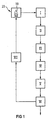
- FIG. 1 shows a schematic representation of the process of inventive method.
- a flame 10 in a combustion chamber 23 is monitored by a detection device I.
- the detection device I measures the spatial distribution at least one characteristic of the combustion Parameters that allow conclusions about the soot loading. Either the temperature or the carbon monoxide content or temperature and carbon monoxide content recorded together. This is followed by a calculation or a Comparison II a determination of the local soot formation rate, which provides a soot formation field III.
- the soot formation area III is summed up by an integration IV and if necessary averaged.
- the soot loading of the combustion chamber determined that displayed through a suitable edition VI is printed out or saved.
- the soot loading can be given to a regulation VII based on the flame 10 and thus acts on the combustion. hereby a firing control is achieved.
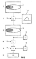
- Process steps I to VI are shown in more detail in FIG. First, a temperature field 11 of the flame 10 detected. Based on the determination of the local soot load on the temperature field 11, a conversion curve 12 is used either determined by experiment or by physical and / or chemical relationships have been calculated. such Conversion curves 12 are also in the VDI heat atlas and printed in "Technical Combustion", Warnatz, Springer-Verlag.
- the temperature field 11 and the conversion curve 12 are linked in a comparison module 13 and deliver Field 14 of the soot formation rate.
- This field 14 of the soot formation rate is transmitted to an integrator 15, which has a spatial and / or time totaling. Possibly can also be averaged after the integration.
- the total soot formation rate is calculated by the integration, which then with a calibration factor 16 from a Memory element C linked in a link module 17 becomes. This calculates the soot load, which is then is passed on to an output module 18.
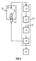
- FIG. 3 shows schematically a device for implementation of the method according to the invention.
- the flame 10 in the combustion chamber 23 is fed by a burner 21.
- to Monitoring is provided by one or more sensors 22, which are at least a parameter characteristic of the combustion measure up.
- This can be a CCD camera.
- Advantageous the spatial distribution of is measured Temperature and / or carbon monoxide content.
- the measured value is on the comparison module 13 passed on, in which the field 14 of the Soot formation rate is determined.
- the comparison module 13 transmits the field 14 of the soot formation rate to the integrator 15, in which the summation and possibly averaging takes place.
- the Calibration factor 16 determines the soot load. This soot load is delivered to the output module 18.
- the output module 18 transmits the soot load to a printer or memory 20.
- a printer or memory 20 there is a feedback to the Burner 21 of the flame 10 with direct, immediate monitoring of the flame 10 and therefore achieved very short dead times.
- the comparison module 13, the integrator 15, the link module 17 and the Output module 18 are combined in a data processing system 19.
Abstract
Description
Die vorliegende Erfindung betrifft ein Verfahren sowie eine Vorrichtung zur Ermittlung der Rußbeladung eines Verbrennungsraums in laufendem Betrieb.The present invention relates to a method and a Device for determining the soot load in a combustion chamber in operation.
Bei der Verbrennung eines fossilen Brennstoffs in einem Verbrennungsraum steht die ständige Verbesserung des Verbrennungsprozesses im Vordergrund der Bemühungen. Dies gilt nicht nur für gasförmige Schadstoffe, wie Kohlenmonoxid und Stickoxide, sondern auch für die Beladung des Abgases mit Feststoffen, wie Ruß. Zum Erreichen eines möglichst guten Verbrennungsprozesses muß die Feuerung mittels einer geeigneten Feuerungsregelung optimiert werden. Bei der Verwendung von fossilem Brennstoff oder Müll treten nämlich auf Grund der unterschiedlichen Herkunft des Brennstoffs oder der heterogenen Zusammensetzung des Mülls Schwankungen des Heizwertes des Brennstoffs oder der Müllmischung auf. Bei Brennstoffmischungen kann darüber hinaus das Verhältnis der einzelnen Brennstoffe zueinander schwanken.When burning a fossil fuel in a combustion chamber stands the constant improvement of the combustion process in the forefront of efforts. This is not the case only for gaseous pollutants such as carbon monoxide and Nitrogen oxides, but also for loading the exhaust gas with Solids, such as carbon black. To achieve the best possible The combustion process must be carried out using a suitable furnace Firing control can be optimized. When using of fossil fuel or garbage come to shame the different origins of the fuel or the heterogeneous Composition of the garbage fluctuations in the calorific value of fuel or garbage mix. For fuel mixtures can also change the relationship of each Fuels fluctuate with each other.
Eine Möglichkeit der Optimierung stellt die Ermittlung der Rußbeladung im laufenden Betrieb dar, wobei die ermittelte Rußbeladung anschließend für die Regelung der Flamme verwendet wird. Ein bekanntes Vorgehen besteht in einer punktuellen Absaugung von Abgasen mit Rußanteilen mit Hilfe einer Absaugsonde. Die Absaugung kann entweder im Verbrennungsraum oder in einem nachgeschalteten Abgassystem erfolgen. Anschließend wird die abgesaugte Luftmenge überprüft und hierdurch die Rußbeladung ermittelt. Eine vollständige Erfassung der Rußbeladung ist mit diesem Vorgehen nicht möglich, da lediglich ein punktuelles Absaugen erfolgt. Lokale Schwankungen der Rußbeladung in dem Verbrennungsraum oder im Abgassystem führen daher zu einer Verzerrung. Darüber hinaus wird die bei der Verbrennung entstehende Rußbeladung erst mit einer gewissen Verzögerungszeit erfaßt. Die vorgesehene Feuerungsregelung arbeitet somit stets mit einer vergleichsweise großen Totzeit, die bei größeren Kraftwerksanlagen bis zu einigen Minuten betragen kann.One way of optimization is to determine the Soot loading during operation, the determined Soot loading then used to control the flame becomes. A known procedure consists of a selective one Extraction of exhaust gases with soot content using a suction probe. The extraction can either be in the combustion chamber or take place in a downstream exhaust system. Subsequently the extracted air volume is checked and thereby the soot load is determined. A complete record soot loading is not possible with this procedure, since only a selective suction takes place. Local fluctuations the soot load in the combustion chamber or in the exhaust system therefore lead to a distortion. In addition, the at the soot load resulting from the combustion only with a certain Delay time recorded. The intended firing regulation thus always works with a comparatively large one Dead time, which is up to a few for larger power plants Minutes.
Ein anderer Ansatz sieht die Ermittlung der Rußbeladung von Flammen mit Hilfe von Laserabsorptionsmessungen über die Mie-Theorie vor. Dieses Meßverfahren ist allerdings nur zu Forschungszwecken im Labor geeignet, da die Messung der Rußbeladung einer Flamme sehr aufwendig ist. Ein Einsatz im täglichen Dauerbetrieb ist derzeit nicht möglich.Another approach involves determining the soot load of Flames using laser absorption measurements using Mie theory in front. However, this measurement method is only for research purposes Suitable in the laboratory because the measurement of the soot load a flame is very expensive. A daily use Continuous operation is currently not possible.
In der US 5,797,736 ist ein Verfahren und eine Vorrichtung beschrieben, mittels derer eine Flammenbildung in einem Verbrennungsprozeß geregelt wird. Dabei werden Sensoren eingesetzt, welche in und nahe der Flamme charakteristische Parameter der Verbrennung, wie z.B. die Temperatur, die Verteilung von Partikeln usw., detektieren.In US 5,797,736 is a method and an apparatus described by means of which flame formation in a Combustion process is regulated. Here sensors are used, which are characteristic parameters in and near the flame combustion, e.g. the temperature, the distribution of particles, etc., detect.
Es wird in oben genannter Schrift jedoch nicht näher ausgeführt, wie z.B. quantitativ eine Rußbeladung eines Verbrennungsraums ermittelt wird. Es geht hauptsächlich darum, qualitative Unregelmäßigkeiten - wie z.B. Fluktuationen in der Temperaturverteilung der Flamme ("cooler spots"), welche u.a. von einer unregelmäßigen Verteilung von Verbrennungspartikeln verursacht sein können - in der Flamme zu detektieren, um eine Anordnung aus Strahlreflektoren so auszurichten, daß Strahlungsenergie der Flamme gezielt auf "cooler spots" innerhalb der Flamme reflektiert wird. Dadurch wird die Verbrennung gleichmäßiger.However, it is not detailed in the above-mentioned document, such as. quantitatively a soot load in a combustion chamber is determined. It's mainly about qualitative Irregularities - such as Fluctuations in the Temperature distribution of the flame ("cooler spots"), which among other things of an irregular distribution of combustion particles can be caused - to detect in the flame to a Align the array of beam reflectors so that Radiant energy of the flame targeted at "cool spots" within the flame is reflected. This will make the Burn more evenly.
Eine quantitative Ermittlung der Rußbeladung eines Verbrennungsraumes ist mit letztgenanntem Verfahren und Vorrichtung nicht möglich. A quantitative determination of the soot load in a combustion chamber is with the latter method and device not possible.
Aus der DE 2 950 690 A1 ist die Messung einer Rußbeladung zur Regelung eines Verbrennungsvorgangs bekannt.DE 2 950 690 A1 describes the measurement of a soot load Regulation of a combustion process known.
Aufgabe der vorliegenden Erfindung ist es, ein Verfahren, bei dem mindestens ein für die Verbrennung charakteristischer Parameter, der einen Rückschluß auf die Rußbeladung erlaubt, durch Überwachung einer Flamme eines Verbrennungsraumes gemessen und die Rußbeladung basierend auf der Messung ermittelt wird, sowie eine Vorrichtung zur Durchführung des Verfahrens bereitzustellen, welche eine rasche und einfache Ermittlung der Rußbeladung eines Verbrennungsraums im laufenden Betrieb ermöglichen.The object of the present invention is to provide a method the at least one parameter characteristic of the combustion, which allows conclusions to be drawn about the soot load, measured by monitoring a flame of a combustion chamber and determines the soot loading based on the measurement is, as well as a device for performing the method provide a quick and easy investigation the soot loading of a combustion chamber while it is running Enable operation.
Erfindungsgemäß wird diese Aufgabe bei einem Verfahren der eingangs genannten Art dadurch gelöst, daß die räumliche Verteilung der Temperatur und/oder der Gehalt an Kohlenmonoxid als für die Verbrennung charakteristischer Parameter gemessen werden, eine Rußbildungsrate durch einen Vergleich mit vorgegebenen Umrechnungskurven ermittelt wird und die Rußbeladung mittels einer Integration über die Rußbildungsrate ermittelt wird.According to the invention, this object is achieved in a method of type mentioned solved in that the spatial distribution the temperature and / or the content of carbon monoxide measured as parameters characteristic of the combustion a soot formation rate by comparison with predetermined ones Conversion curves are determined and the soot load determined by means of an integration via the soot formation rate becomes.
Derartige Umrechnungskurven sind für verschiedene Brennstoffe beispielsweise in dem "VDI-Wärmeatlas" und in "Technische Verbrennung", Warnatz, Springer Verlag, abgedruckt. Alternativ oder zusätzliche können diese Umrechnungskurven durch Versuche für verschiedene Brennstoffe oder Brennstoffzusammensetzungen ermittelt und in Form eines Kennfelds abgelegt werden.Such conversion curves are for different fuels for example in the "VDI Heat Atlas" and in "Technical Combustion ", Warnatz, Springer Verlag, printed. Alternatively or additional can use these conversion curves Trials for different fuels or fuel compositions determined and stored in the form of a map become.
Die räumliche Verteilung der Temperatur läßt sich durch einen oder mehrere geeignete Sensoren erfassen. Die Messung ist genau, berührungsfrei, erfordert keine beweglichen Bauteile und erfolgt ohne Verzögerung. Die Messung des Gehalts an Kohlenmonoxid erfolgt beispielsweise über eine Erfassung der Strahlung in dem für Kohlenmonoxid charakteristischen Strahlungsbereich. Dieser Strahlungsbereich wird z.B. durch einen Strahlteiler aus dem Gesamtspektrum der Flamme isoliert und anschließend erfaßt; eine geeignete Auswerteeinheit für die räumliche Verteilung des Kohlenmonoxids ist z.B. eine CCD-Kamera. The spatial distribution of the temperature can be determined by a or detect several suitable sensors. The measurement is accurate non-contact, requires no moving parts and takes place without delay. Measuring the level of carbon monoxide takes place, for example, by detecting the radiation in the radiation range characteristic of carbon monoxide. This radiation area is e.g. through a Beam splitter isolated from the entire spectrum of the flame and then recorded; a suitable evaluation unit for the spatial distribution of carbon monoxide is e.g. a CCD camera.
Die Erfindung schlägt vor, die bisher bekannten direkten Verfahren zur Ermittlung der Rußbeladung durch ein indirektes Verfahren zu ersetzen. Ein Absaugen von rußbeladenen Abgasen oder eine aufwendige direkte Bestimmung der Rußbeladung in der Flamme können vermieden werden. Es wird vielmehr durch einfache Messung ein für die Verbrennung charakteristischer Parameter erfaßt und anschließend die Rußbeladung basierend auf dieser Messung und Vergleich mit vorgegebenen Umrechnungskurven ermittelt. Aufwendige Absaug- und Analyseeinrichtungen sind nicht erforderlich. Weiter erfolgt die Ermittlung der Rußbeladung erfindungsgemäß ohne Zeitverzögerung, so daß eine optimale Feuerungsregelung erreicht werden kann.The invention proposes the previously known direct methods to determine the soot loading by an indirect Procedure to replace. Extraction of soot-laden exhaust gases or a complex direct determination of the soot load in the flame can be avoided. It is rather through simple measurement a characteristic of the combustion Parameters recorded and then the soot loading based on this measurement and comparison with given conversion curves determined. Elaborate suction and analysis devices are not required. The determination continues the soot loading according to the invention without time delay, so that optimal firing control can be achieved.
Durch die Messung der räumlichen Verteilung der Temperatur und/oder des Gehalts an Kohlenmonoxid ist eine im Vergleich zu einer eindimensionalen Messung genauere Ermittlung der Rußbeladung möglich, da beide Größen im Regelfall im Bereich der Flamme nicht konstant sind.By measuring the spatial distribution of temperature and / or the carbon monoxide content is one in comparison for a one-dimensional measurement more precise determination of the Soot loading possible, since both sizes are usually in the range the flame are not constant.
Weiter ändert sich bei turbulenter Verbrennung, wie sie im Verbrennungsraum von Kraftwerken immer vorliegt, die Position der Flamme während der Verbrennung. Eine stationäre Messung an einzelnen ausgewählten Punkten könnte dazu führen, daß die Flamme bei Veränderung ihrer Position nicht durch die Meßeinrichtung erfaßt wird. Bei der Erfassung der räumlichen Verteilung kann dies durch die Vorgabe eines räumlichen Meßbereichs verhindert werden.Further changes in turbulent combustion, as in Combustion chamber of power plants is always present, the position the flame during combustion. A stationary measurement at selected points, the Do not flame through the measuring device when changing their position is detected. When capturing the spatial distribution can do this by specifying a spatial measuring range be prevented.
Vorteilhafte Ausgestaltungen und Weiterbildungen der Erfindung gehen aus den Unteransprüchen hervor.Advantageous refinements and developments of the invention emerge from the subclaims.
In vorteilhafter Ausgestaltung kann für die Meßwerte ein zulässiger Bereich mit einer Untergrenze und/oder Obergrenze vorgegeben werden. Liegt ein Meßwert außerhalb des vorgegebenen Bereichs, so kann dieser bei der Ermittlung der Rußbeladung unberücksichtigt bleiben. Beispielsweise kann bei der Messung der Temperatur eine Untergrenze von z.B. 800 °C festgelegt werden. Bereiche, in denen die Temperatur unter dieser Grenze liegt, können dann als außerhalb der Flamme liegend angesehen werden und bei der Ermittlung der Rußbeladung unberücksichtigt bleiben.In an advantageous embodiment, an allowable for the measured values Area with a lower limit and / or upper limit be specified. If a measured value lies outside the specified one Range, this can be used when determining the soot load to be disregarded. For example, in the Measuring the temperature a lower limit of e.g. 800 ° C become. Areas where the temperature is below this Limit is then considered to be out of flame are considered and not taken into account when determining the soot load stay.
In vorteilhafter Weiterbildung wird aus der gemessenen räumlichen Verteilung der Temperatur und/oder des Gehalts an Kohlenmonoxid die örtliche Rußbildungsrate ermittelt. Dies bedeutet, daß die zu einem oder mehreren diskreten Orten innerhalb des räumlichen Meßbereichs zugehörige örtliche Bildungsrate aus den zu dem diskreten Ort zugehörigen diskreten Meßwerten der Temperatur und/oder des Gehalts an Kohlenmonoxid ermittelt wird, wobei die zum diskreten Ort zugehörigen diskreten Meßwerte der Temperatur und/oder des Gehalts an Kohlenmonoxid aus der räumlichen Verteilung der Meßwerte entnommen werden. Hierdurch wird die Meßgenauigkeit verbessert.In an advantageous development, the measured spatial Distribution of temperature and / or carbon monoxide content the local soot formation rate is determined. This means, that the to one or more discrete locations within local education rate associated with the spatial measurement range from the discrete measured values associated with the discrete location the temperature and / or the carbon monoxide content is determined, the discrete associated with the discrete location Measured values of the temperature and / or the content of carbon monoxide taken from the spatial distribution of the measured values become. This improves the measurement accuracy.
Vorteilhaft wird die örtliche Rußbildungsrate nach physikalischen und/oder chemischen Zusammenhängen errechnet. Hierdurch kann durch Vorgabe des Brennstoffs oder der Brennstoffmischung ohne vorherige Tests und Erfahrungswerte die örtliche Rußbildungsrate bestimmt werden.The local soot formation rate according to physical is advantageous and / or chemical relationships. hereby can by specifying the fuel or the fuel mixture the local one without previous tests and experience Soot formation rate can be determined.
Vorteilhaft wird die ermittelte Rußbildungsrate über den Meßbereich aufsummiert. Hierdurch wird die zu bearbeitende Datenmenge verringert. Gleichzeitig ergibt sich ein Gesamtwert der Rußbildungsrate, der bereits für Kontroll- und Regelungszwecke verwendet werden kann.The determined soot formation rate over the measuring range is advantageous summed up. As a result, the amount of data to be processed reduced. At the same time there is a total value the soot formation rate, which is already used for control and regulation purposes can be used.
Gemäß einer vorteilhaften Weiterbildung wird die ermittelte Rußbildungsrate über einen vorgebbaren Zeitraum aufsummiert. Schwankungen der Flamme, insbesondere auf Grund turbulenter Verbrennung, können zuverlässig erfaßt werden. Gleichzeitig werden Spitzenwerte oder Minimalwerte geglättet. Durch das Aufsummieren kann darüber hinaus eine Kontrolle der Flamme erfolgen. Erlischt die Flamme, so fällt die Rußbildungsrate über einen längeren Zeitraum drastisch ab: Kurzzeitiges Flackern wird durch das Aufsummieren über den vorgebbaren Zeitraum geglättet, während ein Erlöschen der Flamme zu einem dauerhaften Abfall der Rußbildungsrate führt, der durch das erfindungsgemäße Verfahren erkennbar ist. Es ist somit neben der Ermittlung der Rußbeladung auch eine Überwachung der Flamme möglich.According to an advantageous development, the determined Soot formation rate summed up over a predefinable period. Fluctuations in the flame, particularly due to turbulence Combustion, can be reliably detected. simultaneously peak or minimum values are smoothed. By the A control of the flame can also add up respectively. If the flame goes out, the soot formation rate drops drastically over a longer period of time: brief flickering is added up over the predefinable period smoothed while extinguishing the flame to one leads to a permanent drop in the soot formation rate caused by the The inventive method is recognizable. It is next to it the determination of the soot load also a monitoring of Flame possible.
In vorteilhafter Weiterbildung ist der vorgebbare Zeitraum veränderlich. Insbesondere kann dieser Zeitraum in Abhängigkeit von vorangegangenen Messungen verändert werden. Weiter kann beim Anfahren oder bei Lastschwankungen der vorgebbare Zeitraum anders als im gleichbleibenden Dauerbetrieb gewählt werden.The predefinable period is an advantageous further development mutable. In particular, this period can be dependent be changed from previous measurements. Further can be the predefinable when starting off or in the event of load fluctuations Period selected differently than in constant continuous operation become.
Vorteilhaft wird die ermittelte Rußbildungsrate nach dem Aufsummieren gemittelt. Diese Mittelung erlaubt eine Darstellung der Rußbildungsrate bezogen auf die Größe des Meßbereichs, so daß mehrere Flammen oder Verbrennungsräume unterschiedlicher Größe miteinander verglichen werden können.The determined soot formation rate after the addition is advantageous averaged. This averaging allows a representation the soot formation rate based on the size of the measuring range, so that multiple flames or combustion chambers are different Size can be compared.
Gemäß einer vorteilhaften Ausgestaltung wird die ermittelte Rußbeladungsrate vor oder nach dem Aufsummieren mit einem Eichfaktor zur Ermittlung der Rußbeladung verknüpft. Dieser Eichfaktor ermöglicht den Schluß von der Rußbildungsrate auf die Rußbeladung und wird anlagenspezifisch ermittelt.According to an advantageous embodiment, the determined Soot loading rate before or after adding up with a Calibration factor linked to determine the soot load. This Calibration factor enables the conclusion of the soot formation rate the soot load and is determined on a plant-specific basis.
Vorteilhaft ist der Eichfaktor veränderbar, insbesondere in Abhängigkeit von dem Meßwert, der der Flamme zugeführten Verbrennungsluft und/oder weiteren Parametern. Hierdurch wird eine Anpassung an unterschiedliche Randbedingungen erreicht.The calibration factor can advantageously be changed, in particular in Dependence on the measured value supplied to the flame Combustion air and / or other parameters. This will an adaptation to different boundary conditions achieved.
Vorteilhaft werden sowohl die Temperatur als auch der Kohlenmonoxidgehalt gemessen und miteinander verknüpft. Dieses Vorgehen ermöglicht eine Ermittlung der Rußbeladung auf Grund zweier unterschiedlicher Meßwerte und somit eine Kontrolle. Gleichzeitig wird die Genauigkeit erhöht. Both the temperature and the carbon monoxide content are advantageous measured and linked together. This procedure enables determination of the soot load on the ground two different measured values and thus a control. At the same time, the accuracy is increased.
Eine Vorrichtung zur Durchführung des Verfahrens weist erfindungsgemäß mindestens einen Sensor zur Messung der räumlichen Verteilung der Temperatur und/oder des Gehalts an Kohlenmonoxid eine Datenverarbeitungsanlage zur Ermittlung der Rußbildungsrate und einen Integrator zur Ermittlung der Rußbeladung aus der Rußbildungsrate auf. Die Datenverarbeitungsanlage umfaßt insbesondere geeignete Baugruppen oder Module zum Aufsummieren und Mitteln der Rußbildungsrate sowie zur Verknüpfung mit dem Eichfaktor.A device for carrying out the method has according to the invention at least one sensor for measuring the spatial Distribution of temperature and / or carbon monoxide content a data processing system for determining the soot formation rate and an integrator for determining the soot load from the soot formation rate. The data processing system includes in particular suitable assemblies or modules for adding up and averaging the soot formation rate and for linking with the calibration factor.
Vorteilhaft ist mindestens ein Sensor als CCD-Kamera ausgebildet. Derartige "charged-coupled-device"-Kameras erlauben eine Ortsauflösung des Meßbereichs und damit die Erfassung des mindestens einen für die Verbrennung charakteristischen Parameters in räumlicher Verteilung. At least one sensor is advantageously designed as a CCD camera. Allow such "charged-coupled-device" cameras a spatial resolution of the measuring range and thus the detection of at least one characteristic of the combustion Parameters in spatial distribution.
Die ermittelte Rußbildungsrate kann anschließend über eine geeignete Regelung weiterverarbeitet und an den Brenner der Flamme geführt werden.The determined soot formation rate can then be determined using a suitable control processed and sent to the burner Flame.
Nachstehend wird die Erfindung anhand von Ausführungsbeispielen
näher beschrieben, die in schematischer Weise in der
Zeichnung dargestellt sind. Dabei zeigen:
Figur 1 zeigt eine schematische Darstellung des Ablaufs des
erfindungsgemäßen Verfahrens. Eine Flamme 10 in einem Verbrennungsraum
23 wird über eine Erfassungseinrichtung I überwacht.
Die Erfassungseinrichtung I mißt die räumliche Verteilung
mindestens eines für die Verbrennung charakteristischen
Parameters, der einen Rückschluß auf die Rußbeladung erlaubt.
Es werden entweder die Temperatur oder der Gehalt an Kohlenmonoxid
oder Temperatur und Kohlenmonoxidgehalt gemeinsam erfaßt.
Anschließend erfolgt durch eine Berechnung oder einen
Abgleich II eine Ermittlung der örtlichen Rußbildungsrate,
die ein Rußbildungsfeld III liefert. Das Rußbildungsfeld III
wird durch eine Integration IV aufsummiert und gegebenenfalls
gemittelt. Anschließend erfolgt eine Verknüpfung V mit einem
Eichfaktor. Hierdurch wird die Rußbeladung des Verbrennungsraums
ermittelt, die über eine geeignete Ausgabe VI angezeigt,
ausgedruckt oder abgespeichert wird. Zusätzlich kann
die Rußbeladung auf eine Regelung VII gegeben werden, die auf
die Flamme 10 und damit auf die Verbrennung einwirkt. Hierdurch
wird eine Feuerungsregelung erreicht.Figure 1 shows a schematic representation of the process of
inventive method. A
In Figur 2 sind die Verfahrensschritte I bis VI genauer dargestellt.
Zunächst wird ein Temperaturfeld 11 der Flamme 10
erfaßt. Zur Ermittlung der örtlichen Rußbeladung basierend
auf dem Temperaturfeld 11 dient eine Umrechnungskurve 12, die
entweder durch Versuche ermittelt oder nach physikalischen
und/oder chemischen Zusammenhängen errechnet worden ist. Derartige
Umrechnungskurven 12 sind auch in dem VDI-Wärmeatlas
und in "Technische Verbrennung", Warnatz, Springer-Verlag abgedruckt.
Das Temperaturfeld 11 und die Umrechnungskurve 12
werden in einem Vergleichsmodul 13 verknüpft und liefern ein
Feld 14 der Rußbildungsrate. Dieses Feld 14 der Rußbildungsrate
wird an einen Integrator 15 übermittelt, der eine räumliche
und/oder zeitliche Aufsummierung vornimmt. Gegebenenfalls
kann nach der Integration auch eine Mittelung erfolgen.
Durch die Integration wird die gesamte Rußbildungsrate errechnet,
die anschließend mit einem Eichfaktor 16 aus einem
Speicherelement C in einem Verknüpfungsmodul 17 verknüpft
wird. Hierdurch wird die Rußbeladung errechnet, die anschließend
an ein Ausgabemodul 18 weitergegeben wird.Process steps I to VI are shown in more detail in FIG.
First, a
Alternativ kann aus einem anderen Speicherelement C' ein anderer
Eichfaktor 16' verwendet werden, der nach der Ermittlung
des Felds 14 der Rußbildungsrate mit diesem Feld 14 verknüpft
wird. Dies ist gestrichelt gezeigt.Alternatively, another memory element C 'can be used
Calibration factor 16 'can be used after the determination
of
Figur 3 zeigt schematisch eine Vorrichtung zur Durchführung
des erfindungsgemäßen Verfahrens. Die Flamme 10 in dem Verbrennungsraum
23 wird von einem Brenner 21 gespeist. Zur
Überwachung dienen ein oder mehrere Sensoren 22, die mindestens
einen für die Verbrennung charakteristischen Parameter
messen. Hierbei kann es sich um eine CCD-Kamera handeln. Vorteilhaft
erfolgt eine Messung der räumlichen Verteilung von
Temperatur und/oder Kohlenmonoxidgehalt. Der Meßwert wird an
das Vergleichsmodul 13 weitergegeben, in dem das Feld 14 der
Rußbildungsrate ermittelt wird. Das Vergleichsmodul 13 übermittelt
das Feld 14 der Rußbildungsrate an den Integrator 15,
in dem die Aufsummierung und gegebenenfalls Mittelung erfolgt.
In dem Verknüpfungsmodul 17 wird anschließend über den
Eichfaktor 16 die Rußbeladung ermittelt. Diese Rußbeladung
wird an das Ausgabemodul 18 abgegeben. Das Ausgabemodul 18
übermittelt die Rußbeladung an einen Drucker oder Speicher
20. Vorteilhaft erfolgt gleichzeitig eine Rückkopplung zu dem
Brenner 21 der Flamme 10. Hierdurch wird eine Feuerungsregelung
mit direkter, unmittelbarer Überwachung der Flamme 10
und daher sehr geringen Totzeiten erreicht. Das Vergleichsmodul
13, der Integrator 15, das Verknüpfungsmodul 17 sowie das
Ausgabemodul 18 sind in einer Datenverarbeitungsanlage 19 zusammengefaßt.Figure 3 shows schematically a device for implementation
of the method according to the invention. The
Insgesamt ermöglichen das erfindungsgemäße Verfahren und die zugehörige Vorrichtung eine rasche, einfache und hochgenaue Ermittlung der Rußbeladung.Overall, the inventive method and the associated device a quick, simple and highly accurate Determination of the soot load.
Claims (13)
- Method for determining the soot charge in a combustion chamber (23) during operation, in which at least one parameter which is characteristic of combustion and permits a conclusion concerning the soot charge is measured by monitoring a flame (10) in the combustion chamber (23), and the soot charge is determined on the basis of the measurement, characterized in that the spatial distribution of the temperature and/or the content of carbon monoxide is measured as parameter characteristic of combustion, a soot formation rate is determined by comparison with prescribed conversion curves and the soot charge is determined by integration via the soot formation rate.
- Method according to Claim 1, characterized in that a permissible range with a lower bound and/or upper bound is prescribed for the measured values of the at least one parameter characteristic of combustion, and measured values lying outside the prescribed range are not taken into account when determining the soot charge.
- Method according to Claim 1 or 2, characterized in that the local soot formation rate is determined from the measured spatial distribution of the temperature and/or the content of carbon monoxide.
- Method according to Claim 3, characterized in that the local soot formation rate is calculated using physical and/or chemical relationships.
- Method according to either of Claims 3 and 4, characterized in that the determined soot formation rate is summed over the measuring zone.
- Method according to one of Claims 3 to 5, characterized in that the determined soot formation rate is summed over a prescribeable time interval.
- Method according to Claim 6, characterized in that the prescribeable time interval is variable.
- Method according to one of Claims 5 to 7, characterized in that the determined soot formation rate is averaged after the summing.
- Method according to one of Claims 5 to 8, characterized in that the determined soot formation rate before or after the summing is linked to a calibration factor determining the soot charge.
- Method according to Claim 9, characterized in that the calibration factor is variable, in particular as a function of the measured value, the combustion air fed to the flame (10) and/or other parameters.
- Method according to one of Claims 1 to 10, characterized in that the temperature and the carbon monoxide content are measured and linked to one another.
- Device for determining the soot charge in a combustion chamber (23) during operation, in which at least one parameter which is characteristic of combustion and permits a conclusion concerning the soot charge is measured by monitoring a flame (10) in the combustion chamber (23), and the soot charge is determined on the basis of the measurement, characterized by at least one sensor (22) for measuring the spatial distribution of the temperature and/or the content of carbon monoxide, by a computer (19) for determining the soot formation rate and by an integrator (15) for determining the soot charge from the soot formation rate.
- Device according to Claim 12, characterized in that at least one sensor (22) is designed as a CCD camera.
Applications Claiming Priority (3)
| Application Number | Priority Date | Filing Date | Title |
|---|---|---|---|
| DE19841877 | 1998-09-11 | ||
| DE19841877A DE19841877A1 (en) | 1998-09-11 | 1998-09-11 | Method and device for determining the soot loading of a combustion chamber |
| PCT/DE1999/002839 WO2000016010A1 (en) | 1998-09-11 | 1999-09-08 | Method and device for determining the soot charge in a combustion chamber |
Publications (2)
| Publication Number | Publication Date |
|---|---|
| EP1114280A1 EP1114280A1 (en) | 2001-07-11 |
| EP1114280B1 true EP1114280B1 (en) | 2003-12-17 |
Family
ID=7880809
Family Applications (1)
| Application Number | Title | Priority Date | Filing Date |
|---|---|---|---|
| EP99955673A Expired - Lifetime EP1114280B1 (en) | 1998-09-11 | 1999-09-08 | Method and device for determining the soot charge in a combustion chamber |
Country Status (8)
| Country | Link |
|---|---|
| US (1) | US6551094B2 (en) |
| EP (1) | EP1114280B1 (en) |
| JP (1) | JP4365036B2 (en) |
| AT (1) | ATE256843T1 (en) |
| DE (2) | DE19841877A1 (en) |
| DK (1) | DK1114280T3 (en) |
| ES (1) | ES2213396T3 (en) |
| WO (1) | WO2000016010A1 (en) |
Families Citing this family (9)
| Publication number | Priority date | Publication date | Assignee | Title |
|---|---|---|---|---|
| DE10243307B4 (en) * | 2002-09-13 | 2006-06-08 | Deutsches Zentrum für Luft- und Raumfahrt e.V. | Apparatus and method for the controlled production of nano soot particles |
| WO2007022442A1 (en) * | 2005-08-17 | 2007-02-22 | Nuvo Ventures, Llc | Method and system for monitoring plant operating capacity |
| DE102006044114A1 (en) | 2006-09-20 | 2008-03-27 | Forschungszentrum Karlsruhe Gmbh | Method for characterizing the exhaust gas burnout quality in incinerators |
| DE102006060869A1 (en) * | 2006-12-22 | 2008-06-26 | Khd Humboldt Wedag Gmbh | Method for controlling the operation of a rotary kiln burner |
| US8070482B2 (en) * | 2007-06-14 | 2011-12-06 | Universidad de Concepción | Combustion control system of detection and analysis of gas or fuel oil flames using optical devices |
| US8018590B2 (en) * | 2008-10-23 | 2011-09-13 | General Electric Company | Three-dimensional optical sensor and system for combustion sensing and control |
| DE102008056674A1 (en) * | 2008-11-11 | 2010-05-12 | Siemens Aktiengesellschaft | A method and apparatus for monitoring the combustion of a power plant based on a real concentration distribution of a substance |
| US20100324989A1 (en) * | 2009-06-23 | 2010-12-23 | Craig Stephen Etchegoyen | System and Method for Monitoring Efficacy of Online Advertising |
| DE102009030322A1 (en) * | 2009-06-24 | 2010-12-30 | Siemens Aktiengesellschaft | Concept for controlling and optimizing the combustion of a steam generator on the basis of spatially resolved measurement information from the combustion chamber |
Family Cites Families (20)
| Publication number | Priority date | Publication date | Assignee | Title |
|---|---|---|---|---|
| DE2950690A1 (en) * | 1979-12-17 | 1981-06-25 | Servo-Instrument, in Deutschland Alleinvertrieb der BEAB-Regulatoren GmbH u. Co KG, 4050 Mönchengladbach | Regulation of gas burner operation - has exhaust gas sampling to control setting of butterfly valves controlling through flow |
| DE2950689A1 (en) * | 1979-12-17 | 1981-06-25 | Servo-Instrument, in Deutschland Alleinvertrieb der BEAB-Regulatoren GmbH u. Co KG, 4050 Mönchengladbach | CONTROL DEVICE FOR THE COMBUSTION AIR AMOUNT OF A FIREPLACE |
| JPS60196517A (en) * | 1984-03-16 | 1985-10-05 | Toyota Motor Corp | Control mechanism for soot of burner |
| US4620491A (en) * | 1984-04-27 | 1986-11-04 | Hitachi, Ltd. | Method and apparatus for supervising combustion state |
| JPH0227571B2 (en) * | 1984-12-06 | 1990-06-18 | Tokyo Denryoku Kk | NENSHOJOTAISHINDANHOHO |
| JPS62276326A (en) * | 1986-05-26 | 1987-12-01 | Ishikawajima Harima Heavy Ind Co Ltd | Diagnosis of combustion |
| US4926356A (en) * | 1988-02-29 | 1990-05-15 | The Boeing Company | Test apparatus for measuring heat release of certain materials |
| CH680238A5 (en) * | 1989-12-04 | 1992-07-15 | Matter & Siegmann Ag | |
| JPH03207912A (en) * | 1990-01-08 | 1991-09-11 | Hitachi Ltd | Flame spectroscopic image display for gas turbine combustion device |
| US5249954A (en) * | 1992-07-07 | 1993-10-05 | Electric Power Research Institute, Inc. | Integrated imaging sensor/neural network controller for combustion systems |
| DE4305645C2 (en) * | 1993-02-24 | 1996-10-02 | Rwe Entsorgung Ag | Method for determining characteristic properties of processes forming free radicals, use of the method and device for carrying out the method |
| JPH06273322A (en) * | 1993-03-17 | 1994-09-30 | Hitachi Ltd | Camera, spectroscopic system and combustion evaluating system employing them |
| US5575637A (en) * | 1994-11-04 | 1996-11-19 | Air Products And Chemicals, Inc. | Method and device for low-NOx high efficiency heating in high temperature furnaces |
| DE19532539A1 (en) * | 1995-09-04 | 1997-03-20 | Heinz Prof Dr Ing Spliethoff | Process for monitoring power plant output firing |
| US5794549A (en) * | 1996-01-25 | 1998-08-18 | Applied Synergistics, Inc. | Combustion optimization system |
| DE19605287C2 (en) * | 1996-02-13 | 2000-11-02 | Orfeus Combustion Eng Gmbh | Method and device for controlling the travel time of a boiler |
| US5829962A (en) * | 1996-05-29 | 1998-11-03 | L'air Liquide, Societe Anonyme Pour L'etude Et, L'exploitation Des Procedes Georges | Method and apparatus for optical flame control of combustion burners |
| US5993194A (en) * | 1996-06-21 | 1999-11-30 | Lemelson; Jerome H. | Automatically optimized combustion control |
| US5797736A (en) * | 1996-12-03 | 1998-08-25 | University Of Kentucky Research Foundation | Radiation modulator system |
| DE19931111A1 (en) * | 1999-07-06 | 2001-01-11 | Electrowatt Tech Innovat Corp | Flame monitoring device e.g. for refuse burning plant comprises array of semiconductor photodetectors connected to evaluation circuitry |
-
1998
- 1998-09-11 DE DE19841877A patent/DE19841877A1/en not_active Withdrawn
-
1999
- 1999-09-08 AT AT99955673T patent/ATE256843T1/en active
- 1999-09-08 DK DK99955673T patent/DK1114280T3/en active
- 1999-09-08 EP EP99955673A patent/EP1114280B1/en not_active Expired - Lifetime
- 1999-09-08 ES ES99955673T patent/ES2213396T3/en not_active Expired - Lifetime
- 1999-09-08 WO PCT/DE1999/002839 patent/WO2000016010A1/en active IP Right Grant
- 1999-09-08 DE DE59908129T patent/DE59908129D1/en not_active Expired - Lifetime
- 1999-09-08 JP JP2000570504A patent/JP4365036B2/en not_active Expired - Fee Related
-
2001
- 2001-03-12 US US09/803,764 patent/US6551094B2/en not_active Expired - Lifetime
Also Published As
| Publication number | Publication date |
|---|---|
| EP1114280A1 (en) | 2001-07-11 |
| JP2002525544A (en) | 2002-08-13 |
| WO2000016010A1 (en) | 2000-03-23 |
| ATE256843T1 (en) | 2004-01-15 |
| DE19841877A1 (en) | 2000-04-20 |
| US20010019814A1 (en) | 2001-09-06 |
| JP4365036B2 (en) | 2009-11-18 |
| US6551094B2 (en) | 2003-04-22 |
| ES2213396T3 (en) | 2004-08-16 |
| DE59908129D1 (en) | 2004-01-29 |
| DK1114280T3 (en) | 2004-04-13 |
Similar Documents
| Publication | Publication Date | Title |
|---|---|---|
| EP0612961B1 (en) | Method for determining characteristic properties of processes producing radicals | |
| DE60106509T2 (en) | Control method of a burner | |
| EP0156200B1 (en) | Method of and device for determining the mixing ratio of a mixture containing an oxygen carrier and a fuel | |
| DE69923357T2 (en) | Feed / loss method for determining fuel flow, chemical composition, calorific value, and performance of a fossil fuel thermal system | |
| DE2656840C2 (en) | Method and device for regulating the energy supply to a heating device for the combustion chamber of an incineration unit | |
| EP1114280B1 (en) | Method and device for determining the soot charge in a combustion chamber | |
| DE102005006007A1 (en) | Method and system for real-time evaluation of the boiler setting using an emission sensor data map | |
| DE4118781C2 (en) | Wobbe counter | |
| DE102007041871A1 (en) | Compensation of varying fuel and air properties with an ion signal | |
| DE19850338C2 (en) | Method and device for checking and monitoring the aging of a catalytic converter in the exhaust gas of internal combustion engines and the emission of pollutants | |
| EP0156958B1 (en) | Regulation method for the combustion air quantity of a burner apparatus | |
| EP2347178B1 (en) | Method and device for monitoring the combustion of fuel in a power station | |
| EP1890207A1 (en) | Method of generating a process model | |
| EP1697687B1 (en) | Method for determining fluctuating fuel properties during the operation of a power plant | |
| EP4043793A1 (en) | Method and arrangement for detecting flashback in a premix burner | |
| EP1051585B1 (en) | Method and device for operating an incinerator plant | |
| DE4042025C2 (en) | Device and method for evaluating the combustion state in an internal combustion engine | |
| EP3995817A1 (en) | Method and assembly for detecting hydrogen in a heater operable with hydrogen or hydrogen-containing fuel gas | |
| WO2005038345A2 (en) | Device and method for optimizing the exhaust gas burn-out rate in incinerating plants | |
| EP0655583B1 (en) | Method for controlling and monitoring combustion | |
| DE102009057121A1 (en) | Method for qualitative monitoring of combustion status of boiler system in e.g. industrial combustion, involves determining exhaust gas value of combustion of fuel-air-mixture by boiler-isothermal current and/or voltage characteristic curve | |
| DE19637726A1 (en) | Fuel combustion monitoring apparatus from formation of exhaust gas esp. for gas turbine | |
| DE4315969A1 (en) | Method and equipment for optimising combustion plants | |
| DE10153643A1 (en) | Process for monitoring of a combustion system having a burner supplied with fuel comprises simultaneous monitoring of the flame, the oxidizable components of the exhaust gas, and its temperature using a sensor | |
| DE2510718C2 (en) | Compound controller for a gas, oil and coal dust burner |
Legal Events
| Date | Code | Title | Description |
|---|---|---|---|
| PUAI | Public reference made under article 153(3) epc to a published international application that has entered the european phase |
Free format text: ORIGINAL CODE: 0009012 |
|
| 17P | Request for examination filed |
Effective date: 20001201 |
|
| AK | Designated contracting states |
Kind code of ref document: A1 Designated state(s): AT BE CH CY DE DK ES FI FR GB GR IE IT LI LU MC NL PT SE |
|
| 17Q | First examination report despatched |
Effective date: 20020124 |
|
| GRAH | Despatch of communication of intention to grant a patent |
Free format text: ORIGINAL CODE: EPIDOS IGRA |
|
| GRAS | Grant fee paid |
Free format text: ORIGINAL CODE: EPIDOSNIGR3 |
|
| GRAA | (expected) grant |
Free format text: ORIGINAL CODE: 0009210 |
|
| AK | Designated contracting states |
Kind code of ref document: B1 Designated state(s): AT BE CH CY DE DK ES FI FR GB GR IE IT LI LU MC NL PT SE |
|
| PG25 | Lapsed in a contracting state [announced via postgrant information from national office to epo] |
Ref country code: IE Free format text: LAPSE BECAUSE OF FAILURE TO SUBMIT A TRANSLATION OF THE DESCRIPTION OR TO PAY THE FEE WITHIN THE PRESCRIBED TIME-LIMIT Effective date: 20031217 Ref country code: CY Free format text: LAPSE BECAUSE OF FAILURE TO SUBMIT A TRANSLATION OF THE DESCRIPTION OR TO PAY THE FEE WITHIN THE PRESCRIBED TIME-LIMIT Effective date: 20031217 |
|
| REG | Reference to a national code |
Ref country code: GB Ref legal event code: FG4D Free format text: NOT ENGLISH |
|
| REG | Reference to a national code |
Ref country code: CH Ref legal event code: NV Representative=s name: SIEMENS SCHWEIZ AG Ref country code: CH Ref legal event code: EP |
|
| REG | Reference to a national code |
Ref country code: IE Ref legal event code: FG4D Free format text: GERMAN |
|
| REF | Corresponds to: |
Ref document number: 59908129 Country of ref document: DE Date of ref document: 20040129 Kind code of ref document: P |
|
| PG25 | Lapsed in a contracting state [announced via postgrant information from national office to epo] |
Ref country code: GR Free format text: LAPSE BECAUSE OF FAILURE TO SUBMIT A TRANSLATION OF THE DESCRIPTION OR TO PAY THE FEE WITHIN THE PRESCRIBED TIME-LIMIT Effective date: 20040317 |
|
| REG | Reference to a national code |
Ref country code: SE Ref legal event code: TRGR |
|
| REG | Reference to a national code |
Ref country code: DK Ref legal event code: T3 |
|
| GBT | Gb: translation of ep patent filed (gb section 77(6)(a)/1977) |
Effective date: 20040319 |
|
| REG | Reference to a national code |
Ref country code: IE Ref legal event code: FD4D |
|
| REG | Reference to a national code |
Ref country code: ES Ref legal event code: FG2A Ref document number: 2213396 Country of ref document: ES Kind code of ref document: T3 |
|
| PG25 | Lapsed in a contracting state [announced via postgrant information from national office to epo] |
Ref country code: LU Free format text: LAPSE BECAUSE OF NON-PAYMENT OF DUE FEES Effective date: 20040908 |
|
| PG25 | Lapsed in a contracting state [announced via postgrant information from national office to epo] |
Ref country code: MC Free format text: LAPSE BECAUSE OF NON-PAYMENT OF DUE FEES Effective date: 20040930 |
|
| ET | Fr: translation filed | ||
| PLBE | No opposition filed within time limit |
Free format text: ORIGINAL CODE: 0009261 |
|
| STAA | Information on the status of an ep patent application or granted ep patent |
Free format text: STATUS: NO OPPOSITION FILED WITHIN TIME LIMIT |
|
| 26N | No opposition filed |
Effective date: 20040920 |
|
| PG25 | Lapsed in a contracting state [announced via postgrant information from national office to epo] |
Ref country code: PT Free format text: LAPSE BECAUSE OF NON-PAYMENT OF DUE FEES Effective date: 20040517 |
|
| REG | Reference to a national code |
Ref country code: CH Ref legal event code: PCAR Free format text: SIEMENS SCHWEIZ AG;INTELLECTUAL PROPERTY FREILAGERSTRASSE 40;8047 ZUERICH (CH) |
|
| PGFP | Annual fee paid to national office [announced via postgrant information from national office to epo] |
Ref country code: DK Payment date: 20110926 Year of fee payment: 13 |
|
| PGFP | Annual fee paid to national office [announced via postgrant information from national office to epo] |
Ref country code: CH Payment date: 20111213 Year of fee payment: 13 |
|
| PGFP | Annual fee paid to national office [announced via postgrant information from national office to epo] |
Ref country code: FI Payment date: 20120912 Year of fee payment: 14 Ref country code: SE Payment date: 20120911 Year of fee payment: 14 |
|
| PGFP | Annual fee paid to national office [announced via postgrant information from national office to epo] |
Ref country code: BE Payment date: 20121010 Year of fee payment: 14 |
|
| PGFP | Annual fee paid to national office [announced via postgrant information from national office to epo] |
Ref country code: AT Payment date: 20120810 Year of fee payment: 14 |
|
| REG | Reference to a national code |
Ref country code: CH Ref legal event code: PL |
|
| PG25 | Lapsed in a contracting state [announced via postgrant information from national office to epo] |
Ref country code: CH Free format text: LAPSE BECAUSE OF NON-PAYMENT OF DUE FEES Effective date: 20120930 Ref country code: LI Free format text: LAPSE BECAUSE OF NON-PAYMENT OF DUE FEES Effective date: 20120930 |
|
| BERE | Be: lapsed |
Owner name: *SIEMENS A.G. Effective date: 20130930 |
|
| REG | Reference to a national code |
Ref country code: SE Ref legal event code: EUG |
|
| PG25 | Lapsed in a contracting state [announced via postgrant information from national office to epo] |
Ref country code: FI Free format text: LAPSE BECAUSE OF NON-PAYMENT OF DUE FEES Effective date: 20130908 Ref country code: SE Free format text: LAPSE BECAUSE OF NON-PAYMENT OF DUE FEES Effective date: 20130909 |
|
| REG | Reference to a national code |
Ref country code: DK Ref legal event code: EBP Effective date: 20130930 |
|
| REG | Reference to a national code |
Ref country code: AT Ref legal event code: MM01 Ref document number: 256843 Country of ref document: AT Kind code of ref document: T Effective date: 20130908 |
|
| PG25 | Lapsed in a contracting state [announced via postgrant information from national office to epo] |
Ref country code: BE Free format text: LAPSE BECAUSE OF NON-PAYMENT OF DUE FEES Effective date: 20130930 |
|
| PG25 | Lapsed in a contracting state [announced via postgrant information from national office to epo] |
Ref country code: AT Free format text: LAPSE BECAUSE OF NON-PAYMENT OF DUE FEES Effective date: 20130908 |
|
| PG25 | Lapsed in a contracting state [announced via postgrant information from national office to epo] |
Ref country code: DK Free format text: LAPSE BECAUSE OF NON-PAYMENT OF DUE FEES Effective date: 20130930 |
|
| PGFP | Annual fee paid to national office [announced via postgrant information from national office to epo] |
Ref country code: NL Payment date: 20140904 Year of fee payment: 16 |
|
| PGFP | Annual fee paid to national office [announced via postgrant information from national office to epo] |
Ref country code: GB Payment date: 20140908 Year of fee payment: 16 |
|
| PGFP | Annual fee paid to national office [announced via postgrant information from national office to epo] |
Ref country code: IT Payment date: 20140927 Year of fee payment: 16 |
|
| PGFP | Annual fee paid to national office [announced via postgrant information from national office to epo] |
Ref country code: FR Payment date: 20140917 Year of fee payment: 16 Ref country code: ES Payment date: 20141027 Year of fee payment: 16 Ref country code: DE Payment date: 20141120 Year of fee payment: 16 |
|
| REG | Reference to a national code |
Ref country code: DE Ref legal event code: R119 Ref document number: 59908129 Country of ref document: DE |
|
| PG25 | Lapsed in a contracting state [announced via postgrant information from national office to epo] |
Ref country code: IT Free format text: LAPSE BECAUSE OF NON-PAYMENT OF DUE FEES Effective date: 20150908 |
|
| GBPC | Gb: european patent ceased through non-payment of renewal fee |
Effective date: 20150908 |
|
| REG | Reference to a national code |
Ref country code: NL Ref legal event code: MM Effective date: 20151001 |
|
| REG | Reference to a national code |
Ref country code: FR Ref legal event code: ST Effective date: 20160531 |
|
| PG25 | Lapsed in a contracting state [announced via postgrant information from national office to epo] |
Ref country code: GB Free format text: LAPSE BECAUSE OF NON-PAYMENT OF DUE FEES Effective date: 20150908 Ref country code: DE Free format text: LAPSE BECAUSE OF NON-PAYMENT OF DUE FEES Effective date: 20160401 |
|
| PG25 | Lapsed in a contracting state [announced via postgrant information from national office to epo] |
Ref country code: FR Free format text: LAPSE BECAUSE OF NON-PAYMENT OF DUE FEES Effective date: 20150930 Ref country code: NL Free format text: LAPSE BECAUSE OF NON-PAYMENT OF DUE FEES Effective date: 20151001 |
|
| REG | Reference to a national code |
Ref country code: ES Ref legal event code: FD2A Effective date: 20170306 |
|
| PG25 | Lapsed in a contracting state [announced via postgrant information from national office to epo] |
Ref country code: ES Free format text: LAPSE BECAUSE OF NON-PAYMENT OF DUE FEES Effective date: 20150909 |