EP1113615B1 - Sende-Diversityerkennungsanordnung und Erkennungsverfahren - Google Patents
Sende-Diversityerkennungsanordnung und Erkennungsverfahren Download PDFInfo
- Publication number
- EP1113615B1 EP1113615B1 EP00128288A EP00128288A EP1113615B1 EP 1113615 B1 EP1113615 B1 EP 1113615B1 EP 00128288 A EP00128288 A EP 00128288A EP 00128288 A EP00128288 A EP 00128288A EP 1113615 B1 EP1113615 B1 EP 1113615B1
- Authority
- EP
- European Patent Office
- Prior art keywords
- symbol
- transmission diversity
- antenna
- modulated
- primary cpich
- Prior art date
- Legal status (The legal status is an assumption and is not a legal conclusion. Google has not performed a legal analysis and makes no representation as to the accuracy of the status listed.)
- Expired - Lifetime
Links
- 230000005540 biological transmission Effects 0.000 title claims description 116
- 238000001514 detection method Methods 0.000 title claims description 29
- 238000004891 communication Methods 0.000 claims description 10
- 238000001228 spectrum Methods 0.000 claims description 5
- 238000010276 construction Methods 0.000 description 13
- 238000000034 method Methods 0.000 description 12
- 238000010586 diagram Methods 0.000 description 5
- 238000013442 quality metrics Methods 0.000 description 5
- 238000007792 addition Methods 0.000 description 4
- 230000010355 oscillation Effects 0.000 description 4
- 230000001419 dependent effect Effects 0.000 description 3
- 230000003044 adaptive effect Effects 0.000 description 2
- 238000012937 correction Methods 0.000 description 2
- 238000012935 Averaging Methods 0.000 description 1
- 206010022998 Irritability Diseases 0.000 description 1
- 101150041689 SLC25A5 gene Proteins 0.000 description 1
- 101150092978 Slc25a4 gene Proteins 0.000 description 1
- 238000011161 development Methods 0.000 description 1
- 230000018109 developmental process Effects 0.000 description 1
- 238000009434 installation Methods 0.000 description 1
- 230000010363 phase shift Effects 0.000 description 1
- 239000004065 semiconductor Substances 0.000 description 1
Images


Classifications
-
- H—ELECTRICITY
- H04—ELECTRIC COMMUNICATION TECHNIQUE
- H04L—TRANSMISSION OF DIGITAL INFORMATION, e.g. TELEGRAPHIC COMMUNICATION
- H04L1/00—Arrangements for detecting or preventing errors in the information received
- H04L1/02—Arrangements for detecting or preventing errors in the information received by diversity reception
- H04L1/06—Arrangements for detecting or preventing errors in the information received by diversity reception using space diversity
- H04L1/0618—Space-time coding
-
- H—ELECTRICITY
- H04—ELECTRIC COMMUNICATION TECHNIQUE
- H04L—TRANSMISSION OF DIGITAL INFORMATION, e.g. TELEGRAPHIC COMMUNICATION
- H04L1/00—Arrangements for detecting or preventing errors in the information received
- H04L1/0001—Systems modifying transmission characteristics according to link quality, e.g. power backoff
- H04L1/0023—Systems modifying transmission characteristics according to link quality, e.g. power backoff characterised by the signalling
- H04L1/0025—Transmission of mode-switching indication
Definitions
- the present invention relates generally to a transmission diversity detection circuit, a detection method thereof and a storage medium storing a transmission diversity detection program. More particularly, the invention relates to a transmission diversity detection circuit, a detection method thereof and a storage medium storing a transmission diversity detection program, applicable for spread spectrum communication performing transmission diversity, and especially applicable for the case where presence or absence of transmission diversity is notified by modulation of a SCH (Synchronization channel).
- a SCH Synchrononization channel
- a transmission diversity since a plurality of paths between the base station and a mobile station are established, communication can be performed even when receiving condition in one path is not good, if receiving condition of another path is good.
- a transmission diversity system applicable for spread spectrum communication has been disclosed in 3GPP (3rd Generation Partnership Project) specification TS25.211 V3.0.0 (TSGR1#7(99)g0). This transmission diversity system will be discussed with reference to Figs. 7 to 13.
- Fig. 7 there is shown a transmission pattern of a primary CPICH (common pilot channel) symbol in the transmission diversity.
- CPICH common pilot channel
- one frame is consisted of fifteen time slots (hereinafter,merely called as "slot") #0 to #14. Accordingly, since one frame is consisted of odd number of slots, "-A" and “A” are transmitted from the antenna 2 at the boundary of the frame FB (frame boundary). At portions other than the boundary FB, "A”, “A” and “-A”, “-A” are transmitted alternately from the antenna 2 as set forth above.
- the primary CPICH symbol is not transmitted on the side of the antenna 2, and only primary CPICH symbol on the side of the antenna 1 is transmitted.
- a transmission pattern of the SCH represents both of a primary SCH and a secondary SCH.
- Respective SCHs are those, in which the symbol 1 + j is spread with a primary synchronization code and a secondary synchronization code. These SCHs are further modulated with "a".
- Fig. 8 there is shown the slots #0 to #14 forming one frame. It is assumed that a period T slot of the slot is 2560 chips. On the other hand, a period T frame is 15 x T slot . Then, in one slot, after transmission of 256 chips of the primary SCH and the secondary SCH, data portion indicated by a primary CCPCH (Common Control Physical Channel) is transmitted.
- a primary CCPCH Common Control Physical Channel
- Cp in the primary SCH is a primary synchronization code.
- a takes a value of "1” or "-1" according to the following condition. Namely, concerning the data portion indicated by primary CCPCH in Fig. 8, when transmission diversity is performed in a method called as space time block coding based transmit antenna diversity (STTD), "a” is “1” and when STTD transmission diversity is not performed, “a” becomes "-1".
- STTD space time block coding based transmit antenna diversity
- FIG. 9 is a block diagram showing a construction of a primary portion of the base station for performing STTD transmission diversity.
- the base station is constructed with a STTD encoder 41 for inputting a quadrature phase shift keying (QPSK) symbol, a multiplexer (MUX) 42 being input an encoded output of the encoder 41, a pilot signal and a diversity pilot signal, a multipliers 43a and 43b for spreading an output of the multiplexer 42 with a scramble code C, and antennas 1 and 2 provided corresponding to the multipliers 43a and 43b.
- QPSK quadrature phase shift keying
- MUX multiplexer
- the STTD encoder 41 converts input symbol as shown in Fig. 10.
- Fig. 10 among input signal to the STTD encoder 41, in a front portion of the data portion N data , symbols S 1 and S 2 are present. Namely, during a period from a time 0 to a time T, symbol S 1 is present, and during a period from the time T to a time 2T, the symbol S 2 is present.
- the STTD encoder 41 outputs symbols S 1 and S 2 as they are, to the side of the antenna 1 (Ant1).
- a complex conjugate -S 2 * of the symbol S 2 and a complex conjugate S 1 * of the symbol S 1 are output alternately.
- the symbol S 1 is transmitted from the antenna 1.
- the complex conjugate -S 2 * of the symbol S 2 is transmitted from the antenna 2.
- the symbol S 2 is transmitted from the antenna 1, and at the same time, the complex conjugate S 1 * of the symbol S 1 is transmitted from the antenna 2.
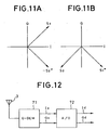
- the symbol S 1 and the complex conjugate -S 2 * are transmitted during the period from the time 0 to the time T as shown in Fig. 11A.
- the symbol S 2 and the complex conjugate S 1 * are transmitted during the period from the time T to the time 2T as shown in Fig. 11B.
- the complex conjugate of the symbol is output from the antenna 2.
- the signal arriving from the antenna 1 during the period from the time 0 to the time T and the signal arriving from the antenna 2 during the period from the time 0 to the time T are situated in a relationship to weaken with each other
- the signal arriving from the antenna 1 during the period from the time T to the time 2T and the signal arriving from the antenna 2 during the period from the time T to the time 2T are inherently situated in a relationship to strengthen with each other.
- paths P1 to Pj (j is a natural number) are present as propagation paths.
- Signals received by the antenna 3 becomes a sum of symbols transmitted from the antennas 1 and 2 at the same timing and varied amplitudes and phases through a plurality of paths. Even if the signals received by the antenna is weaken due to variation of the amplitude and the phase caused by the paths during a certain period, i.e. either the period from 0 to T or the period from T to 2T, the arriving signals from a plurality of paths are strengthened with each other in another period, to increase probability of correct reception.
- Fig. 12 shows a typical construction of the major part on a reception side in relation to the base station.
- the reception side is constructed with a reception antenna 3, a demodulator (Q-DEM) 71 corresponding to the foregoing encoder and an A/D converter 27 which converts an analog signal Ia and Qa into digital signals Id and Qd.
- Q-DEM demodulator
- A/D converter 27 which converts an analog signal Ia and Qa into digital signals Id and Qd.
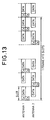
- Fig. 13 shows a transmission diversity pattern of the SCH.
- the transmission diversity system is those called as TSTD (time switched transmit diversity for SCH) and is different from the foregoing STTD transmission diversity.
- TSTD time switched transmit diversity for SCH
- the SCH is performed only from the antenna 1. Accordingly, irrespective presence or absence of the TSTD transmission diversity, the SCH is never transmitted from a plurality of antennas, simultaneously.
- phase of the symbol through the propagation paths becomes indeterminative. Therefore, on the basis of phase difference with a known symbol to be a reference of the phase, the direction of modulation "a" of the SCH is predicted.
- phase rotation is caused between the symbols to require simultaneously perform prediction and correction of phase rotation to make process quite complicate.
- US-A-5,940,454 discloses a switch diversity control apparatus.
- a receiver for receiving a radio signal carrying digitally-encoded data has a plurality of diversity antennas, respectively coupled to inputs of a selector.
- a received signal selected by the selector is equalized by an adaptive equalizer and then demodulated to recover data, when possible.
- a quality metric dependent on the quality of the recovered data is generated.
- a switch controller responsive to the quality metric controls the selector. After the controller controls the selector to select a new antenna, it monitors the quality metric as the adaptive equalizer retrains and, if the quality metric does not exceed a predetermined threshold before a predetermined forward guard time expires, the controller causes the selector to select another antenna.
- the switch controller may also receive a signal level signal dependent on the level of the received signal. After the controller controls the selector to select a new antenna, if the level of the received signal is less than a predetermined threshold the demodulator recovers data, if possible, for a short, predetermined time and, if the quality metric derived therefrom does not exceed a predetermined threshold, the controller controls the selector to select another antenna after the short, predetermined time.
- the present invention has been worked out in view of the drawbacks in the prior art set forth above. It is therefore an object of the present invention to provide a transmission diversity detection circuit, a transmission diversity detection method and a storage medium storing a transmission diversity detection program, which can detect presence or absence of a STTD transmission diversity by simply arithmetic operation.
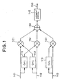
- Fig. 1 is a block diagram showing a construction of the preferred embodiment of a STTD transmission diversity detection circuit according to the present invention.
- Fig. 1 there is shown a construction on a receiver side of the shown system.
- the receiver of the shown system is constructed with complex conjugate calculating portion (Conj.) 111, 112 and 113 for calculating respective complex conjugates for respective complex signals input to complex input portions 101, 102 and 103, complex multipliers 121, 122 and 123 for performing multiplication, a complex adder 130 adding results of multiplication (products) of the multipliers, and judgment portion 140 for making judgment whether transmission diversity is present or not depending upon sign of the result of addition.
- Conj. complex conjugate calculating portion
- 111, 112 and 113 for calculating respective complex conjugates for respective complex signals input to complex input portions 101, 102 and 103
- complex multipliers 121, 122 and 123 for performing multiplication
- a complex adder 130 adding results of multiplication (products) of the multipliers
- judgment portion 140
- (0)th primary CPICH symbol (to be expressed by C 2n,0 ) in even number slot
- (0) th SCH symbol (to be expressed by S 2n,0 ) in even number slot at the same position
- the first primary CPICH symbol (to be expressed as C 2n,1 ) in even number slot are input, respectively.
- the complex conjugate calculating portions 111,112 and 113 calculate complex conjugates of input complex signals and output the resultant complex conjugates. From the complex conjugate calculating portion 111, a complex conjugate C 2n,0 * of the complex signal C 2n,0 is output. From the complex conjugate calculating portion 112, a complex conjugate S 2n,0 * of the complex signal S 2n,0 is output. From the complex conjugate calculating portion 113, a complex conjugate C 2n,1 * of the complex signal C 2n,1 is output. It should be noted that the complex conjugate calculating portions 111, 112 and 113 take I signal and Q signal as inputs, derive the complex conjugates with inverting the Q signal and output resultant complex conjugates, as shown in Fig. 2.
- the complex multipliers 121, 122 and 123 perform complex multiplication of two input complexes and output products. From the complex multiplier 121, C 2n,0 * S 2n,0 * is output. From the complex multiplier 122, C 2n,0 S 2n,0 is output. From the complexmultiplier 123, C 2n,1 ⁇ C 2n,1 * is output.
- the complex adder 130 calculates a sum of input three complex number C 2n,0 ⁇ S 2n,0 v + C 2n,0 * ⁇ S 2n,0 + C 2n,1 ⁇ C 2n,1 * and outputs the sum.
- the judgment portion 140 makes judgment whether transmission diversity is present or not on the basis of the result output from the complex adder 130.
- the result of judgment is output from a judgment result output portion 150.
- (0)th primary CPICH symbol in (2n) th even number slot is expressed by C 2n,0
- (0) th SCH symbol in (2n) th even number slot at the same position is expressed by S 2n,0
- the subsequent first primary CPICH symbol at the same slot is expressed as C 2n,1 .
- Respective symbols are transmitted with spread by a spread code in the base station.
- despreading with correct spreading code and correct timing is performed for the reception signal, and restoration of the symbol is already completed at the reception side.
- the character coefficient of the transmission path from the first antenna 1 of the base station to the antenna on the reception side is ⁇ 1 and the characteristic coefficient of the transmission path from the second antenna 2 of the base station to the antenna of the terminal on the reception side is ⁇ 2 .
- characteristics coefficient ⁇ 1 is to be considered.
- These characteristic coefficients ⁇ 1 and ⁇ 2 are complex including the phase and amplitude.
- Figs. 3A and 3B meaning of the characteristic chart will be discussed with reference to Figs. 3A and 3B.
- the transmission side even when transmission is performed in a relationship of the orthogonal coordinate axes as shown in Fig. 3A, it can be received in the relationship of the orthogonal axes as shown in Fig. 3B due to error between reference oscillation frequency between the transmission side and the reception side, or due to rotation of the phase caused by characteristics of the propagation path.
- One expressing the relationship shown in Figs. 3A and 3B is the characteristic coefficient.
- the characteristic coefficient from the transmission antenna 1 to the reception antenna 3 is ⁇ 1
- the transmitted symbol A is received as ⁇ 1 ⁇ A.
- the characteristic coefficient from the transmission antenna 2 to the reception antenna is ⁇ 2
- the transmitted symbol A is received as ⁇ 2 ⁇ A.
- the arithmetic operations are performed.
- the complex conjugate C 2n,0 * of C 2n,0 the complex conjugate S 2n,0 * of S 2n,0 and the complex conjugate C 2n,1 * of C 2n,1 are calculated by the complex conjugate calculating portions 111, 112 and 113 shown in Fig. 1.
- calculation by the following equations (7) to (9) are performed by the complex multipliers 121, 122 and 123 to output the result of calculation.
- the output of the complex adder 130 in Fig. 1 is as expressed by the following equation (15).
- C 2 ⁇ n , 0 ⁇ S 2 ⁇ n , 0 * + C 2 ⁇ n , 0 * ⁇ S 2 ⁇ n , 0 + C 2 ⁇ n , 1 * ⁇ C 2 ⁇ n , 1 -
- the result of calculation becomes only scalar amount.
- the result of calculation becomes positive value (sign is plus) when STTD transmission diversity is performed, and becomes negative value (sign is minus) when STTD transmission diversity is not performed. From the foregoing, with the shown system, by the sign of the result of calculation, it becomes possible to detect whether STTD transmission diversity is performed or not. It should be noted that by performing the detection process for a plurality of even numbered slots and averaging the result of detection, diversity detection with higher certainty can be performed.
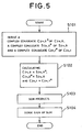
- the transmission diversity detection method shown in Fig. 5 can be realized. Namely, as shown in Fig. 5, at first, the complex conjugate C 2n,0 * of C 2n,0 , the complex conjugate S 2n,0 * of S 2n,0 and the complex conjugate C 2n,1 * of C 2n,1 are derived (step S101). Next, multiplication C 2n,0 ⁇ S 2n,0 * , multiplication C 2n,0 * ⁇ S 2n,0 and multiplication C 2n,1 ⁇ C 2n,1 * are performed respectively (step S102). Then, addition of the results of multiplication (products) is performed (step S103). Finally, concerning the result of addition, judgment is made whether the sign of the resultant value is positive or negative (step S104). By performing the foregoing method, it can be detected whether transmission diversity is performed or not.
- a process shown in Fig. 6 is performed. Namely, referring to Fig. 6, comparing the sign D and zero (0), when the sign D is smaller than or equal to zero, judgment can be made that the transmission diversity is not performed to perform normal reception process. On the other hand, when the sign D is greater than zero, judgment can be made that transmission diversity is performed to perform reception process adapting to transmission diversity. As set forth above, reference is made to the result of calculation to check sign of the result of calculation, then whether the transmission diversity is performed or not can be easily detected.
- arithmetic operation for the detection process set forth above may be performed upon reception by the receiver, namely upon communication, or upon position registration for communication.
- a storage medium storing a program for realizing the process shown in Figs. 5 and 6 is prepared to control the computer using the stored program to perform transmission diversity detection process.
- a storage medium a semiconductor memory, a magnetic disk drive and other various storage medium may be used.
- the present invention can detect presence or absence of STTD transmission diversity by simple arithmetic operation.
- presence or absence of STTD transmission diversity can be detected within a short period, namely within a period of two symbols at the shortest.
- presence or absence of STTD transmission diversity can be detected without requiring particular prediction and correction process.
Landscapes
- Engineering & Computer Science (AREA)
- Computer Networks & Wireless Communication (AREA)
- Signal Processing (AREA)
- Quality & Reliability (AREA)
- Radio Transmission System (AREA)
- Mobile Radio Communication Systems (AREA)
Claims (11)
- Erfassungsschaltung der Übertragungsdiversität, um das Vorhandensein oder das Nichtvorhandensein einer Übertragungsdiversität einer Spreizspektrumkommunikation durch Modulation eines Synchronisationskanals, der nachfolgend als SCH bezeichnet wird, zu benachrichtigen, die aufweist:ein arithmetisches Mittel (111, 112, 113, 121, 122, 123, 130) zur Berechnung eines berechneten Wertes von C2n,0 x S2n,0 * + C2n,0 * x S2n,0 + C2n,1 * x C2n,1, wobei 2n die Schlitzzahl ist, in ersten und zweiten Symbolen in einer vorbestimmten Anzahl der Reihen der Schlitze hinsichtlich eines Empfangssignal, wobei ein primäres gemeinsames Pilotkanalsymbol, das nachfolgend als CPICH-Symbol bezeichnet wird, hinsichtlich des ersten Symbols als C2n,0, ein SCH-Symbol hinsichtlich des ersten Symbols als S2n,0 und ein primäres CPICH-Symbol hinsichtlich des zweiten Symbols als C2n,1 dargestellt werden,wobei ein konjugiert Komplexes des primären CPICH-Symbols C2n,0 als C2n,0 *, ein konjugiert Komplexes des SCH-Symbols S2n,0 als S2n,0 * und ein konjugiert Komplexes des primären CPICH-Symbols C2n,1 als C2n,1 * dargestellt werden, und
ein Beurteilungsmittel (140), um eine Beurteilung durchzuführen, ob oder ob nicht eine Übertragungsdiversität vorliegt in Abhängigkeit davon, ob der berechnete Wert positiv oder negativ ist,
wobei, wenn Übertragungsdiversität durchgeführt wird, das SCH-Symbol um +1 moduliert wird und mit einer ersten Antenne (1) in geradzahligen Schlitze übertragen wird und mit einer zweiten Antenne (2) in ungeradzahligen Schlitzen übertragen wird und wobei, wenn Übertragungsdiversität nicht durchgeführt wird, das SCH-Symbol um -1 moduliert wird und immer mit der ersten Antenne (1) übertragen wird und
wobei, wenn Übertragungsdiversität durchgeführt wird, das primäre CPICH um +1 moduliert wird und mit einer ersten Antenne (1) übertragen wird, wobei auch gleichzeitig das primäre CPICH-Symbol um eine vorbestimmte Sequenz von +1 oder -1 moduliert wird und mit der zweiten Antenne (2) übertragen wird, wobei das erste Symbol in jedem geradzahligen Schlitz um +1 1 moduliert wird und das zweite Symbol in jedem geradzahligen Schlitz um -1 moduliert wird, wobei, wenn Übertragungsdiversität nicht durchgeführt wird, das primäre CPICH-Symbol um +1 moduliert wird und nur mit der ersten Antenne (1) übertragen wird. - Erfassungsschaltung der Übertragungsdiversität nach Anspruch 1, wobei das arithmetische Mittel aufweist:Schaltungen (111, 112, 113), um das konjugiert Komplexe C2n,0 * von dem primären CPICH-Symbol C2n,0, ein konjugiert Komplexes S2n,0 * von dem SCH-Symbol S2n,0 und ein konjugiert Komplexes C2n,1 * von dem primären CPICH-Symbol C2n,1 abzuleiten,Multiplizierer (121, 122, 123), um C2n,0 x S2n,0 *, C2n,0 * x S2n,0 und C2n,1 * x C2n,1 zu berechnen, undeinen Addierer (130), um die Summe C2n,0 x S2n,0 * + C2n,0 * x S2n,0 + C2n,1 * x C2n,1 zu berechnen,wobei das Beurteilungsmittel (140) eine Beurteilung in Abhängigkeit von dem positiven oder dem negativen Vorzeichen der Summe durchführt, ob oder ob nicht Übertragungsdiversität durchgeführt wird.
- Erfassungsschaltung der Übertragungsdiversität nach Anspruch 1, wobei der vorbestimmte Schlitz ein geradzahliger Schlitz in einem Rahmen ist und das erste und das zweite Symbol ein nulltes und ein erstes Symbol des Schlitzes sind.
- Erfassungsschaltung der Übertragungsdiversität nach Anspruch 1, wobei nach Durchführen der Kommunikation das arithmetische Mittel (111, 112, 113, 121, 122, 123, 130) eine arithmetische Operation durchführt.
- Erfassungsschaltung der Übertragungsdiversität nach Anspruch 1, wobei nach Registrieren einer Position für die Kommunikation das arithmetische Mittel (111, 112, 113, 121, 122, 123, 130) eine arithmetische Operation durchführt.
- Erfassungsverfahren der Übertragungsdiversität, um das Vorhandensein oder das Nichtvorhandensein einer Übertragungsdiversität einer Spreizspektrumkommunikation durch Modulation eines Synchronisationskanals zu benachrichtigen, das aufweist:einen Berechnungsschritt zur Berechnung eines berechneten Wertes von C2n,0 x S2n,0 * + C2n,0* x S2n,0 + C2n,1 * x C2,1, wobei 2n die Schlitzzahl ist, in ersten und zweiten Symbolen in einer vorbestimmten Anzahl der Reihen der Schlitze hinsichtlich eines Empfangssignal, wobei ein primäres CPICH-Symbol hinsichtlich des ersten Symbols als C2n,0, ein SCH-Symbol hinsichtlich des ersten Symbols als S2n,0 und ein primäres CPICH-Symbol hinsichtlich des zweiten Symbols als C2n,1 dargestellt werden, und wobei ein konjugiert Komplexes des primären CPICH-Symbols C2n,0 als C2n,0 *, ein konjugiert Komplexes des SCH-Symbols S2n,0 als S2n,0 * und ein konjugiert Komplexes des primären CPICH-Symbols C2n,1 als C2n,1 * dargestellt werden, undeinen Beurteilungsschritt, um eine Beurteilung durchzuführen, ob oder ob nicht eine Übertragungsdiversität vorliegt in Abhängigkeit davon, ob der berechnete Wert positiv oder negativ ist,wobei, wenn Übertragungsdiversität durchgeführt wird, das SCH-Symbol um +1 moduliert wird und mit einer ersten Antenne (1) in geradzahligen Schlitze übertragen wird und mit einer zweiten Antenne (2) in ungeradzahligen Schlitzen übertragen wird und wobei, wenn Übertragungsdiversität nicht durchgeführt wird, das SCH-Symbol um -1 moduliert wird und immer mit der ersten Antenne (1) übertragen wird und
wobei, wenn Übertragungsdiversität durchgeführt wird, das primäre CPICH um +1 moduliert wird und mit der ersten Antenne (1) übertragen wird, wobei auch gleichzeitig das primäre CPICH-Symbol um eine vorbestimmte Sequenz von +1 oder -1 moduliert wird und mit der zweiten Antenne (2) übertragen wird, wobei das erste Symbol in jedem geradzahligen Schlitz um +1 moduliert wird und das zweite Symbol in jedem geradzahligen Schlitz um -1 moduliert wird, wobei, wenn Übertragungsdiversität nicht durchgeführt wird, das primäre CPICH-Symbol um +1 moduliert wird und nur mit der ersten Antenne (1) übertragen wird. - Erfassungsverfahren der Übertragungsdiversität nach Anspruch 6, wobei der Berechnungsschritt Schritte aufweist:(S101) Ableiten des konjugiert Komplexen C2n,0 * von dem primären CPICH-Symbol C2n,0, eines konjugiert Komplexen S2n,0 * von dem SCH-Symbol S2n,0 und eines konjugiert Komplexen C2n,1 * von dem primären CPICH-Symbol C2n,1,(S102) Berechnen von C2n,0 x S2n,0 *, C2n,0 * x S2n,0 und C2n,1 * x C2n,1, und(S103) Berechnen der Summe C2n,0 x S2n,0 * + C2n,0 * x S2n,0 + C2n,1 * x C2n,1,wobei der Beurteilungsschritt (S 140) eine Beurteilung in Abhängigkeit von dem positiven oder dem negativen Vorzeichen der Summe durchführt, ob oder ob nicht Übertragungsdiversität durchgeführt wird.
- Erfassungsverfahren der Übertragungsdiversität nach Anspruch 6, wobei der vorbestimmte Schlitz ein geradzahliger Schlitz in einem Rahmen ist und das erste und das zweite Symbol ein nulltes und ein erstes Symbol des Schlitzes sind.
- Speichermedium, das ein Programm speichert, das ein Erfassungsverfahren der Übertragungsdiversität implementiert, um das Vorhandensein oder das Nichtvorhandensein einer Übertragungsdiversität einer Spreizspektrumkommunikation durch Modulation eines Synchronisationskanals zu benachrichtigen, wobei das Programm aufweist:einen Berechnungsschritt zur Berechnung eines berechneten Wertes von C2n,0 x S2n,0 * + C2n,0 * x S2n,0 + C2n,1 * x C2n,1, wobei 2n die Schlitzzahl ist, in ersten und zweiten Symbolen in einer vorbestimmten Anzahl der Reihen der Schlitze hinsichtlich eines Empfangssignal, wobei ein primäres CPICH-Symbol hinsichtlich des ersten Symbols als C2n,0, ein SCH-Symbol hinsichtlich des ersten Symbols als S2n,0 und ein primäres CPICH-Symbol hinsichtlich des zweiten Symbols als C2n,1 dargestellt werden und wobei ein konjugiert Komplexes des primären CPICH-Symbols C2n,0 als C2n,0 *, ein konjugiert Komplexes des SCH-Symbols S2n,0 als S2n,0 * und ein konjugiert Komplexes des primären CPICH-Symbols C2n,1 als C2n,1 * dargestellt werden, undeinen Beurteilungsschritt, um eine Beurteilung durchzuführen, ob oder ob nicht eine Übertragungsdiversität vorliegt in Abhängigkeit davon, ob der berechnete Wert positiv oder negativ ist,wobei, wenn Übertragungsdiversität durchgeführt wird, das SCH-Symbol um +1 moduliert wird und mit einer ersten Antenne (1) in geradzahligen Schlitze übertragen wird und mit einer zweiten Antenne (2) in ungeradzahligen Schlitzen übertragen wird und wobei, wenn Übertragungsdiversität nicht durchgeführt wird, das SCH-Symbol um -1 moduliert wird und immer mit der ersten Antenne (1) übertragen wird und
wobei, wenn Übertragungsdiversität durchgeführt wird, das primäre CPICH um +1 moduliert wird und mit der ersten Antenne (1) übertragen wird, wobei auch gleichzeitig das primäre CPICH-Symbol um eine vorbestimmte Sequenz von +1 oder -1 moduliert wird und mit der zweiten Antenne (2) übertragen wird, wobei das erste Symbol in jedem geradzahligen Schlitz um +1 moduliert wird und das zweite Symbol in jedem geradzahligen Schlitz um -1 moduliert wird, wobei, wenn Übertragungsdiversität nicht durchgeführt wird, das primäre CPICH-Symbol um +1 moduliert wird und nur mit der ersten Antenne (1) übertragen wird. - Speichermedium nach Anspruch 9, wobei der Berechnungsschritt Schritte auf weist:(S101) Ableiten des konjugiert Komplexen C2n,0 * von dem primären CPICH-Symbol C2n,0, eines konjugiert Komplexen S2n,0 * von dem SCH-Symbol S2n,0 und eines konjugiert Komplexen C2n,1 * von dem primären CPICH-Symbol C2n,1,(S102) Berechnen von C2n,0 x S2n,0 *, C2n,0 * x S2n,0 und C2n,1 * x C2n,1, und(S103) Berechnen der Summe C2n,0 x S2n,0 * + C2n,0 * × S2n,0 + C2n,1 * x C2n,1,wobei der Beurteilungsschritt (S 140) eine Beurteilung in Abhängigkeit von dem positiven oder dem negativen Vorzeichen der Summe durchführt, ob oder ob nicht Übertragungsdiversität durchgeführt wird.
- Speichermedium nach Anspruch 9, wobei der vorbestimmte Schlitz ein geradzahliger Schlitz in einem Rahmen ist und das erste und das zweite Symbol ein nulltes und ein erstes Symbol des Schlitzes sind.
Applications Claiming Priority (2)
| Application Number | Priority Date | Filing Date | Title |
|---|---|---|---|
| JP36859999 | 1999-12-27 | ||
| JP36859999 | 1999-12-27 |
Publications (3)
| Publication Number | Publication Date |
|---|---|
| EP1113615A2 EP1113615A2 (de) | 2001-07-04 |
| EP1113615A3 EP1113615A3 (de) | 2005-07-20 |
| EP1113615B1 true EP1113615B1 (de) | 2007-07-11 |
Family
ID=18492250
Family Applications (1)
| Application Number | Title | Priority Date | Filing Date |
|---|---|---|---|
| EP00128288A Expired - Lifetime EP1113615B1 (de) | 1999-12-27 | 2000-12-22 | Sende-Diversityerkennungsanordnung und Erkennungsverfahren |
Country Status (5)
| Country | Link |
|---|---|
| US (1) | US6859484B2 (de) |
| EP (1) | EP1113615B1 (de) |
| CN (1) | CN100380854C (de) |
| AU (1) | AU770433B2 (de) |
| DE (1) | DE60035479T2 (de) |
Families Citing this family (9)
| Publication number | Priority date | Publication date | Assignee | Title |
|---|---|---|---|---|
| FI20010874L (fi) * | 2001-04-26 | 2002-10-27 | Nokia Corp | Tiedonsiirtomenetelmä ja -laitteisto |
| KR100401954B1 (ko) * | 2001-11-01 | 2003-10-17 | 한국전자통신연구원 | 기지국의 시공 전송 다이버시티 부호화 사용 여부 판정장치 및 그 방법 |
| DE10250861B4 (de) | 2002-10-31 | 2007-01-04 | Infineon Technologies Ag | Verfahren und Vorrichtungen zur Detektion des TX-Diversity-Modes für Mobilfunkempfänger |
| DE10347985B4 (de) * | 2003-10-15 | 2005-11-10 | Infineon Technologies Ag | Verfahren und Vorrichtung zur Erkennung von Sendeantennendiversität im Empfänger sowie zur Scrambling-Code-Indentifizierung |
| TWI280003B (en) * | 2005-04-14 | 2007-04-21 | Ind Tech Res Inst | System and method for transmission diversity status detection |
| US7684508B1 (en) * | 2005-05-27 | 2010-03-23 | Mediatek Incorporation | Transmission diversity detecting apparatus capable of generating quality indicator and related method thereof |
| KR101276797B1 (ko) * | 2005-08-24 | 2013-06-20 | 한국전자통신연구원 | 이동 통신 시스템에서의 송신 다이버시티 방법 및 기지국송신기 |
| WO2007138666A1 (ja) * | 2006-05-29 | 2007-12-06 | Panasonic Corporation | 無線基地局装置 |
| US8565775B2 (en) * | 2008-06-25 | 2013-10-22 | Qualcomm Incorporated | Methods and apparatus for common channel cancellation in wireless communications |
Family Cites Families (7)
| Publication number | Priority date | Publication date | Assignee | Title |
|---|---|---|---|---|
| US5812935A (en) * | 1993-04-17 | 1998-09-22 | Hughes Electronics | Cellular system employing base station transmit diversity according to transmission quality level |
| US5623485A (en) * | 1995-02-21 | 1997-04-22 | Lucent Technologies Inc. | Dual mode code division multiple access communication system and method |
| JP3337613B2 (ja) * | 1996-03-05 | 2002-10-21 | シャープ株式会社 | スペクトル拡散通信システム |
| JP3763949B2 (ja) * | 1997-09-25 | 2006-04-05 | 若間金物株式会社 | スライドヒンジ |
| US5940454A (en) * | 1997-12-17 | 1999-08-17 | Nortel Networks Corporation | Blind switch diversity control apparatus |
| KR19990088235A (ko) * | 1998-05-13 | 1999-12-27 | 윤종용 | 이동통신시스템의시간스위칭송신다이버시티장치및그제어방법 |
| US6862434B2 (en) * | 2002-07-26 | 2005-03-01 | Qualcomm Inc. | Transmission diversity systems |
-
2000
- 2000-12-21 US US09/740,975 patent/US6859484B2/en not_active Expired - Fee Related
- 2000-12-22 EP EP00128288A patent/EP1113615B1/de not_active Expired - Lifetime
- 2000-12-22 DE DE60035479T patent/DE60035479T2/de not_active Expired - Lifetime
- 2000-12-22 AU AU72518/00A patent/AU770433B2/en not_active Ceased
- 2000-12-27 CN CNB001376241A patent/CN100380854C/zh not_active Expired - Fee Related
Non-Patent Citations (1)
| Title |
|---|
| None * |
Also Published As
| Publication number | Publication date |
|---|---|
| US6859484B2 (en) | 2005-02-22 |
| CN100380854C (zh) | 2008-04-09 |
| EP1113615A2 (de) | 2001-07-04 |
| US20010006531A1 (en) | 2001-07-05 |
| EP1113615A3 (de) | 2005-07-20 |
| AU770433B2 (en) | 2004-02-19 |
| DE60035479D1 (de) | 2007-08-23 |
| AU7251800A (en) | 2001-06-28 |
| DE60035479T2 (de) | 2008-04-17 |
| CN1304233A (zh) | 2001-07-18 |
Similar Documents
| Publication | Publication Date | Title |
|---|---|---|
| US6853839B2 (en) | Method of antenna-weight estimation and mobile communication terminal | |
| EP1263179B1 (de) | Kanalschätzung in einem CDMA-System mit codierten Steuersymbolen als zusätzlichen Pilotsymbolen | |
| EP0993130B1 (de) | Raum-Zeit blockkodierte Sendeantennediversity für WCDMA | |
| EP1128586B1 (de) | Basisstation und Endgerät mit adaptiver Modulation | |
| CA2076061A1 (en) | Method of forming a channel estimate for a time-varying radio channel | |
| US20020196733A1 (en) | Carrier phase recovery of multi-rate signals | |
| US6424642B1 (en) | Estimation of doppler frequency through autocorrelation of pilot symbols | |
| US20070230628A1 (en) | Apparatus and method for detecting a signal in a communication system using Multiple Input Multiple Output scheme | |
| EP0898400A2 (de) | Kommunikationsverfahren, Sende- und Empfangsvorrichtungen und zellulares Radio-Kommunikationssystem | |
| KR20070081786A (ko) | 통신시스템에서 다중입출력을 위한 신호 수신 방법 및 장치 | |
| EP1322045A1 (de) | Vorrichtung und verfahren zum funkempfang | |
| US6426978B1 (en) | Digital communication systems and methods for differential and/or amplitude encoding and decoding secondary symbols | |
| EP1113615B1 (de) | Sende-Diversityerkennungsanordnung und Erkennungsverfahren | |
| KR20050006290A (ko) | 전송 전에 사전 회전을 이용하는 코드 분할 다중 접속시스템 | |
| US6546026B1 (en) | Multi-diversity synchronization technique for improving synchronization performance in wireless applications over fading channels | |
| US7890839B2 (en) | Radio communication apparatus suppressing correction error while maintaining communication quality, and method and program for error correction | |
| US7095727B2 (en) | System and method for determining use of STTD encoding of base system | |
| US5946345A (en) | Apparatus and a method for telecommunication system | |
| EP1475932B1 (de) | Interferenzsignalerkennung und Kanalschätzung für drahtlose Kommunikationsnetze | |
| EP2153540B1 (de) | Verfahren und vorrichtung zur reduzierten gitter-demodulation | |
| JP2590441B2 (ja) | 干渉波検出方法 | |
| JP4079964B2 (ja) | 無線受信装置及びアンテナ・ベリフィケーション方法 | |
| CN1805306B (zh) | 移动站装置和移动站装置的控制方法 | |
| JP3551922B2 (ja) | 送信ダイバシティ検出回路、検出方法、記録媒体 | |
| US8204463B2 (en) | Method for antenna verification |
Legal Events
| Date | Code | Title | Description |
|---|---|---|---|
| PUAI | Public reference made under article 153(3) epc to a published international application that has entered the european phase |
Free format text: ORIGINAL CODE: 0009012 |
|
| AK | Designated contracting states |
Kind code of ref document: A2 Designated state(s): AT BE CH CY DE DK ES FI FR GB GR IE IT LI LU MC NL PT SE TR |
|
| AX | Request for extension of the european patent |
Free format text: AL;LT;LV;MK;RO;SI |
|
| PUAL | Search report despatched |
Free format text: ORIGINAL CODE: 0009013 |
|
| AK | Designated contracting states |
Kind code of ref document: A3 Designated state(s): AT BE CH CY DE DK ES FI FR GB GR IE IT LI LU MC NL PT SE TR |
|
| AX | Request for extension of the european patent |
Extension state: AL LT LV MK RO SI |
|
| 17P | Request for examination filed |
Effective date: 20050608 |
|
| AKX | Designation fees paid |
Designated state(s): DE FR GB IT |
|
| GRAP | Despatch of communication of intention to grant a patent |
Free format text: ORIGINAL CODE: EPIDOSNIGR1 |
|
| GRAS | Grant fee paid |
Free format text: ORIGINAL CODE: EPIDOSNIGR3 |
|
| GRAA | (expected) grant |
Free format text: ORIGINAL CODE: 0009210 |
|
| AK | Designated contracting states |
Kind code of ref document: B1 Designated state(s): DE FR GB IT |
|
| REG | Reference to a national code |
Ref country code: GB Ref legal event code: FG4D |
|
| REF | Corresponds to: |
Ref document number: 60035479 Country of ref document: DE Date of ref document: 20070823 Kind code of ref document: P |
|
| ET | Fr: translation filed | ||
| PLBE | No opposition filed within time limit |
Free format text: ORIGINAL CODE: 0009261 |
|
| STAA | Information on the status of an ep patent application or granted ep patent |
Free format text: STATUS: NO OPPOSITION FILED WITHIN TIME LIMIT |
|
| 26N | No opposition filed |
Effective date: 20080414 |
|
| REG | Reference to a national code |
Ref country code: GB Ref legal event code: 732E Free format text: REGISTERED BETWEEN 20141023 AND 20141029 |
|
| REG | Reference to a national code |
Ref country code: FR Ref legal event code: TP Owner name: LENOVO INNOVATIONS LIMITED (HONG KONG), HK Effective date: 20141119 |
|
| PGFP | Annual fee paid to national office [announced via postgrant information from national office to epo] |
Ref country code: DE Payment date: 20141216 Year of fee payment: 15 Ref country code: GB Payment date: 20141217 Year of fee payment: 15 |
|
| PGFP | Annual fee paid to national office [announced via postgrant information from national office to epo] |
Ref country code: FR Payment date: 20141208 Year of fee payment: 15 |
|
| PGFP | Annual fee paid to national office [announced via postgrant information from national office to epo] |
Ref country code: IT Payment date: 20141203 Year of fee payment: 15 |
|
| REG | Reference to a national code |
Ref country code: DE Ref legal event code: R119 Ref document number: 60035479 Country of ref document: DE |
|
| GBPC | Gb: european patent ceased through non-payment of renewal fee |
Effective date: 20151222 |
|
| REG | Reference to a national code |
Ref country code: FR Ref legal event code: ST Effective date: 20160831 |
|
| PG25 | Lapsed in a contracting state [announced via postgrant information from national office to epo] |
Ref country code: DE Free format text: LAPSE BECAUSE OF NON-PAYMENT OF DUE FEES Effective date: 20160701 Ref country code: GB Free format text: LAPSE BECAUSE OF NON-PAYMENT OF DUE FEES Effective date: 20151222 |
|
| PG25 | Lapsed in a contracting state [announced via postgrant information from national office to epo] |
Ref country code: FR Free format text: LAPSE BECAUSE OF NON-PAYMENT OF DUE FEES Effective date: 20151231 |
|
| PG25 | Lapsed in a contracting state [announced via postgrant information from national office to epo] |
Ref country code: IT Free format text: LAPSE BECAUSE OF NON-PAYMENT OF DUE FEES Effective date: 20151222 |