EP1113518B1 - Electrolyte à base d'oxide solide, module de cellule à combustible et méthode de fabrication - Google Patents
Electrolyte à base d'oxide solide, module de cellule à combustible et méthode de fabrication Download PDFInfo
- Publication number
- EP1113518B1 EP1113518B1 EP00123637.1A EP00123637A EP1113518B1 EP 1113518 B1 EP1113518 B1 EP 1113518B1 EP 00123637 A EP00123637 A EP 00123637A EP 1113518 B1 EP1113518 B1 EP 1113518B1
- Authority
- EP
- European Patent Office
- Prior art keywords
- sheet
- electrolyte
- indentations
- ceramic
- flexible ceramic
- Prior art date
- Legal status (The legal status is an assumption and is not a legal conclusion. Google has not performed a legal analysis and makes no representation as to the accuracy of the status listed.)
- Expired - Lifetime
Links
Images


Classifications
-
- C—CHEMISTRY; METALLURGY
- C04—CEMENTS; CONCRETE; ARTIFICIAL STONE; CERAMICS; REFRACTORIES
- C04B—LIME, MAGNESIA; SLAG; CEMENTS; COMPOSITIONS THEREOF, e.g. MORTARS, CONCRETE OR LIKE BUILDING MATERIALS; ARTIFICIAL STONE; CERAMICS; REFRACTORIES; TREATMENT OF NATURAL STONE
- C04B35/00—Shaped ceramic products characterised by their composition; Ceramics compositions; Processing powders of inorganic compounds preparatory to the manufacturing of ceramic products
- C04B35/01—Shaped ceramic products characterised by their composition; Ceramics compositions; Processing powders of inorganic compounds preparatory to the manufacturing of ceramic products based on oxide ceramics
- C04B35/48—Shaped ceramic products characterised by their composition; Ceramics compositions; Processing powders of inorganic compounds preparatory to the manufacturing of ceramic products based on oxide ceramics based on zirconium or hafnium oxides, zirconates, zircon or hafnates
- C04B35/486—Fine ceramics
-
- C—CHEMISTRY; METALLURGY
- C04—CEMENTS; CONCRETE; ARTIFICIAL STONE; CERAMICS; REFRACTORIES
- C04B—LIME, MAGNESIA; SLAG; CEMENTS; COMPOSITIONS THEREOF, e.g. MORTARS, CONCRETE OR LIKE BUILDING MATERIALS; ARTIFICIAL STONE; CERAMICS; REFRACTORIES; TREATMENT OF NATURAL STONE
- C04B35/00—Shaped ceramic products characterised by their composition; Ceramics compositions; Processing powders of inorganic compounds preparatory to the manufacturing of ceramic products
- C04B35/622—Forming processes; Processing powders of inorganic compounds preparatory to the manufacturing of ceramic products
- C04B35/62222—Forming processes; Processing powders of inorganic compounds preparatory to the manufacturing of ceramic products obtaining ceramic coatings
-
- H—ELECTRICITY
- H01—ELECTRIC ELEMENTS
- H01M—PROCESSES OR MEANS, e.g. BATTERIES, FOR THE DIRECT CONVERSION OF CHEMICAL ENERGY INTO ELECTRICAL ENERGY
- H01M8/00—Fuel cells; Manufacture thereof
- H01M8/10—Fuel cells with solid electrolytes
- H01M8/12—Fuel cells with solid electrolytes operating at high temperature, e.g. with stabilised ZrO2 electrolyte
- H01M8/124—Fuel cells with solid electrolytes operating at high temperature, e.g. with stabilised ZrO2 electrolyte characterised by the process of manufacturing or by the material of the electrolyte
- H01M8/1246—Fuel cells with solid electrolytes operating at high temperature, e.g. with stabilised ZrO2 electrolyte characterised by the process of manufacturing or by the material of the electrolyte the electrolyte consisting of oxides
- H01M8/1253—Fuel cells with solid electrolytes operating at high temperature, e.g. with stabilised ZrO2 electrolyte characterised by the process of manufacturing or by the material of the electrolyte the electrolyte consisting of oxides the electrolyte containing zirconium oxide
-
- Y—GENERAL TAGGING OF NEW TECHNOLOGICAL DEVELOPMENTS; GENERAL TAGGING OF CROSS-SECTIONAL TECHNOLOGIES SPANNING OVER SEVERAL SECTIONS OF THE IPC; TECHNICAL SUBJECTS COVERED BY FORMER USPC CROSS-REFERENCE ART COLLECTIONS [XRACs] AND DIGESTS
- Y02—TECHNOLOGIES OR APPLICATIONS FOR MITIGATION OR ADAPTATION AGAINST CLIMATE CHANGE
- Y02E—REDUCTION OF GREENHOUSE GAS [GHG] EMISSIONS, RELATED TO ENERGY GENERATION, TRANSMISSION OR DISTRIBUTION
- Y02E60/00—Enabling technologies; Technologies with a potential or indirect contribution to GHG emissions mitigation
- Y02E60/30—Hydrogen technology
- Y02E60/50—Fuel cells
-
- Y—GENERAL TAGGING OF NEW TECHNOLOGICAL DEVELOPMENTS; GENERAL TAGGING OF CROSS-SECTIONAL TECHNOLOGIES SPANNING OVER SEVERAL SECTIONS OF THE IPC; TECHNICAL SUBJECTS COVERED BY FORMER USPC CROSS-REFERENCE ART COLLECTIONS [XRACs] AND DIGESTS
- Y02—TECHNOLOGIES OR APPLICATIONS FOR MITIGATION OR ADAPTATION AGAINST CLIMATE CHANGE
- Y02P—CLIMATE CHANGE MITIGATION TECHNOLOGIES IN THE PRODUCTION OR PROCESSING OF GOODS
- Y02P70/00—Climate change mitigation technologies in the production process for final industrial or consumer products
- Y02P70/50—Manufacturing or production processes characterised by the final manufactured product
-
- Y—GENERAL TAGGING OF NEW TECHNOLOGICAL DEVELOPMENTS; GENERAL TAGGING OF CROSS-SECTIONAL TECHNOLOGIES SPANNING OVER SEVERAL SECTIONS OF THE IPC; TECHNICAL SUBJECTS COVERED BY FORMER USPC CROSS-REFERENCE ART COLLECTIONS [XRACs] AND DIGESTS
- Y10—TECHNICAL SUBJECTS COVERED BY FORMER USPC
- Y10T—TECHNICAL SUBJECTS COVERED BY FORMER US CLASSIFICATION
- Y10T428/00—Stock material or miscellaneous articles
- Y10T428/24—Structurally defined web or sheet [e.g., overall dimension, etc.]
- Y10T428/24149—Honeycomb-like
-
- Y—GENERAL TAGGING OF NEW TECHNOLOGICAL DEVELOPMENTS; GENERAL TAGGING OF CROSS-SECTIONAL TECHNOLOGIES SPANNING OVER SEVERAL SECTIONS OF THE IPC; TECHNICAL SUBJECTS COVERED BY FORMER USPC CROSS-REFERENCE ART COLLECTIONS [XRACs] AND DIGESTS
- Y10—TECHNICAL SUBJECTS COVERED BY FORMER USPC
- Y10T—TECHNICAL SUBJECTS COVERED BY FORMER US CLASSIFICATION
- Y10T428/00—Stock material or miscellaneous articles
- Y10T428/24—Structurally defined web or sheet [e.g., overall dimension, etc.]
- Y10T428/24355—Continuous and nonuniform or irregular surface on layer or component [e.g., roofing, etc.]
Definitions
- the present invention is in the field of electrochemical devices and more particularly relates to flexible ceramic sheets for solid electrolytes and electrolyte/electrode assemblies for devices such as fuel cells.
- Curved electrode and electrolyte designs that reduce the thermal stresses arising during the normal operation of fuel cells are disclosed in published PCT patent application WO99/44254 .
- the use of corrugated planar electrode/electrolyte sheets to control such stresses is proposed by K. Tomida et al. in "Preparation of Solid Electrolyte Thin Films for Relaxing Thermal Stresses", Proceedings of the Third International Symposium on Solid Oxide Fuel Cells, Proceedings Volume 93-4, pages 74-81, Singhal and Iwahara, Editors, The Electrochemical Society, Inc. (1993 ).
- each planar electrode/electrolyte sub-unit is bonded to and edge-supported by a framing manifold structure, with multiple frames and sub-units being stacked and electrically interconnected in parallel or series to provide the fuel cell output current or voltage required for the particular application of interest.
- the present invention provides highly strain tolerant ceramic electrolyte layers wherein the electrolyte is formed of a strong, thin ceramic sheet incorporating a two-dimensional surface indentation pattern.
- flexible ceramic sheet having a surface indentation pattern providing a strain tolerance of not less than 0.5% in any direction in the sheet plane, more preferably a strain tolerance of at least 1% in any direction in the sheet plane can readily be provided by means hereinafter described.
- Useful indentation patterns are those that impart a very high multi-axial strain tolerance to the sheet, within the plane of the sheet, without introducing stress concentrators that reduce sheet strength.
- suitable indentation patterns are those comprising multi-directional corrugations or waves, protrusions or indentations of circular, polygonal, or other cross-section, and other contiguous or overlapping indentations or protrusions that do not introduce sharp sheet curvature and do not alter the generally planar configuration of the sheet.
- One-dimensional patterns, such as single-direction corrugations that provide only uni-axial strain tolerance, are not useful.
- Strain tolerant electrolyte sheets produced as described can be employed in a variety of different fuel cell configurations, but are of particular value in planar stacked fuel cell designs. This is because the strain-tolerant electrolyte sheets of the invention offer much higher resistance to mechanical failure under temperature cycling conditions, particularly in an edge-supported electrolyte configuration, than do conventional corrugated or other electrolyte sheet designs.
- Patterns that are not useful to build the required multidirectional strain tolerance are those that have straight corrugation ridges, or straight paths or areas of completely flat sheet, running in straight uninterrupted lines from one edge of the sheet to another. Uninterrupted ridge or flat lines in the sheet surface define axes of very low strain tolerance in the sheet plane, greatly increasing the risk of sheet or contact failure in the event that significant stresses along such axes arise in the course of use. Patterns of this type include parallel corrugation patterns, and also many regular indentation patterns based on repeating triangles, squares and rectangles if the indentations are not appropriatedly staggered to avoid linear ridges or flats.
- Figs. 4a-4c of the drawing illustrate multidirectional corrugation patterns that are not useful to provide strain-tolerant electrolyte sheets in accordance with the invention.
- the lines represent the outlines or borders of sheet indentations or protrusions having the shapes enclosed by the lines.
- a shared characteristic of all of these designs is that substantially all of the lines correspond to flat straight paths spanning the entire widths or lengths of the sheets. Accordingly the corrugation patterns shown, although multi-directional in nature, impart essentially no enhanced strain tolerance to the sheets in directions parallel to those span lines.
- Figs. 5a-5f of the drawing illustrate multidirectional corrugation patterns that increase the strain tolerance of the sheet in every direction in the sheet plane.
- the indentation patterns represented by these line drawings are characterized by the complete absence of span lines corresponding to straight ridge or flat lines crossing the entire lengths or widths of the sheets.
- Concentric corrugations are appropriate for circular or near circular electrolyte sheet but are not as useful for rectangles and square sheets. Radial corrugations that have straight ridge lines running from one edge of a square or rectangular sheet to the opposite edge of the sheet are not useful. Concentric corrugations can have curved ridge lines from one edge of a square or rectangular sheet to the adjacent edge of the sheet. Of course, completely a-periodic patterns, if free of straight ridge or flat lines, could also be used.
- impressioning the selected indentation patterns on thin ceramic sheet can be accomplished in a number of different ways. For example, sufficiently thin ceramic sheet materials can be reformed through a process of superplastic deformation at high temperatures below their melting temperatures.
- a green polymer-bonded ceramic powder sheet is made from a zirconia powder as follows.
- a ceramic slip is first prepared by combining a yttria-stabilized zirconia powder (TZ-3Y powder from the Tosoh Corporation, Japan) with a vehicle consisting of a mixture of ethanol, butanol, propylene glycol and water. 100g of the zirconia powder free of contaminants is added to a previously prepared mixture of 36.4g of ethanol, 8.8g of 1-butanol, 2g of propylene glycol, 2.5g of distilled water, and 1g of a liquid dispersant (Emphos PS-21A dispersant from the Witco Chemical Company). The resulting powder dispersion is transferred to a milling bottle and is vibration-milled for 72 hours using zirconia balls as the milling media.
- a yttria-stabilized zirconia powder TZ-3Y powder from the Tosoh Corporation, Japan
- a vehicle consisting of a mixture of
- the milled suspension is processed through a double settling process wherein it is first allowed to settle for 72 hours and the liquid then separated from the sediment by decantation. The resulting slip is then allowed to settle for another 24 hours and separated from the sediment for final processing.
- the slip thus provided is next flocculated through the addition of an alcohol-acetic acid mixture consisting of 50% of glacial acetic acid and 50% of isopropyl alcohol by weight.
- This mixture is added to the slip in a proportion sufficient to provide 1 part of acetic acid for each 100 parts by weight of ceramic powder remaining after settling, and the acidified slip is then shaken to assure complete mixing.
- film-forming additives consisting of about 3.5 parts by weight of a dibutyl pthalate liquid plasticizer and 6 parts by weight of a polyvinyl butyral powder binder are added to the slip for each 100 parts by weight of zirconia powder remaining after settling, with gentle shaking after each addition to achieve thorough mixing.
- the resulting slip has a viscosity suitable for tape casting.
- a flexible cohesive zirconia sheet is formed from this slip by casting it onto a thin methyl cellulose release layer previously applied to a flat casting surface.
- the release layer consists of a dried tape-cast methyl cellulose coating of about 0.0005 inch thickness formed from a 2% (wt.) aqueous solution of Dow K-75 Methocel® cellulose.
- the tape-cast layer thus provided provides a flexible green ceramic sheet layer after the removal of volatile slip vehicle components by drying.
- a supporting acrylic polymer overlayer is tape-cast over the ceramic sheet and dried.
- This overlayer is provided from an acrylate solution containing 71% of ethyl acetate solvent to which 25% of polymethylmethacrylate powder and 3.5% of dibutyl pthalate (Aldrich Chemical Company) have been added.
- the acrylate solution is tape-cast and then dried to provide a flexible polymer film overcoating.
- This layer adheres well to the underlying ceramic sheet layer, providing a cohesive composite sheet consisting of the ceramic sheet and acrylate overcoating. This cohesive composite sheet is easily separated from the cellulose release layer after all layers have been completely dried.
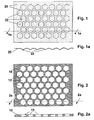
- a metal form with regularly spaced hexagonal cutouts is provided.
- This form consists of a metal grid about 0.6 mm in thickness incorporating hexagonal cutouts in a close-packed array made up of offset rows of hexagons forming a honeycomb pattern, with a row-to-row center spacing of 6.5 mm.
- the residual metal framework surrounding the cutouts provides separating ribs about 0.6 mm in width and 0.6 mm in height between each hexagon and its six neighboring hexagons.
- Figs. 2-2a of the drawing illustrate a metal form of this design, wherein a plurality of hexagonal cutouts 12 are arranged in close-packed array within form 10.
- the metal form thus provided is placed on a vacuum table and the table and form are preheated to about 60°C.
- a section of the composite green ceramic sheet about 31cm by 24cm in size made as above described is then placed over the form and an insulating section of polymer foam board is placed over the sheet and form to allow them to reach uniform temperature.
- the vacuum table is then activated for about ten seconds, following which the vacuum is released and the green ceramic sheet is removed from the form and inspected.
- the multi-directionally corrugated sheet resulting from this reforming step is a regularly indented green ceramic sheet incorporating hexagonal indentations separated from each other by spacings corresponding to the spacings between adjacent hexagonal cutouts in the metal honeycomb form.
- This green sheet is trimmed to even rectangular shape with a rotary cloth cutter and then sintered in air on a refractory setter in an electric kiln operating at 1430°C for a period of two hours. The fully sintered sheet is then removed from the kiln and examined.
- Figs. 1-1(a) of the drawing present a schematic top plan and a front elevational cross-sectional view, respectively, of a ceramic sheet 20 which has been fully sintered to set a hexagonal indentation pattern incorporating a plurality of hexagonal indentations 22 established during reforming of the green sheet substantially as above described.
- the sintered sheet will be of zirconia-3 mole% yttria composition with a thickness of about 20 um, supporting an array of hexagonal indentations about 0.15 mm in depth with a row-to-row center spacing of about 4.5 mm between the rows of the hexagons.
- the unusually high multidirectional strain tolerance of this sheet is manifested by an easily discerned stretch or "give" in the sheet when manually stressed in the sheet plane.
- the strain tolerance of the free-standing sheet is measured to be in excess of 1% without cracking.
- Variations in the reforming procedure employed to process green ceramic sheets can be used to change the nature or extent of the indentation patterns developed. For example, using shorter vacuum forming times, e.g., of 1 to 3 or 4 seconds in duration, give shallower corrugations, while using a polyethylene sheet on top of the green ceramic sheet to increase vacuum retention, or using longer forming times, give deeper (higher) corrugations.
- the corrugations would be offset 90 degrees from each other at a ridge spacing of approximately 1 cm, a ridge height of about 2 mm, and a ridge base width of about 1 mm, with a radius of curvature for the ridge edges of 0.4 mm.
- indentation patterns provided in accordance with the invention will have indentation populations along any axis in the plane of the sheet at least adequate to permit theoretical sheet elongations of 1% or greater in all directions within the plane of the sheet.
- the corrugation or other indentation patterns will not incorporate curvature radii below about 2mm or 100x the thickness of the sheet.
- the corrugations or other indentations will preferably not exceed about 2mm in height as measured from the base plane of the sheet.
- a particular advantage of the invention is that alternative indentation patterns adapted to specific applications for strain-tolerant ceramic sheets may be developed to meet particular needs. For example, where high flatness in selected sheet portions is required to meet special electrical contact or electrode processing requirements, sheets incorporating flat sections together with sections incorporating patterned indentations can be provided.
- Fig. 3 of the drawing illustrates one sheet design of this type, incorporating a multi-directionally corrugated or indented border portion 30 incorporating hexagonal indentations 32 surrounding a rectangular flat central section 34.
- This design is particularly well adapted for applications wherein the sheet is to be edge-mounted in a surrounding frame.
- the flat central section of the sheet is isolated from undue stress in all directions in the sheet plane by the surrounding, highly strain tolerant indented border section.
- the strain-tolerant edge portions facilitate edge mounting since gas-tight edge seals requiring larger sheet deformations can be accommodated with a lower risk of sheet failure.
- One fuel cell design to be considered incorporates a yttria-stabilized zirconia electrolyte sheet mounted in a relatively massive surrounding frame that functions as a sheet separator and enclosure for fuel or oxidant gases to be supplied to the sheet.
- Such frames will be of much higher thermal mass than the electrolyte sheet and its supported electrode layers.
- the electrolyte/electrode sheets will be mounted in these frames so that they will be substantially unstressed at fuel cell operating temperatures. If a fuel cell operating temperature of 800C is specified and the cell is turned off, the electrode/electrolyte sheet will cool to ambient temperatures much more rapidly than the frame. In fact, it can be determined from the known thermal expansion coefficient of yttria-stabilized zirconia (110 x 10 -7 /°C) that a strain as high as 0.9% can be developed in an electrolyte/electrode sheet mounted in such a frame at the point of maximum sheet/frame temperature differential during the cooling process. This strain can readily be accommodated by the strain-tolerant electrolyte sheets of the invention.
- any of these various indentation patterns can readily be carried out in a continuous process, and can be accomplished at any one of a number of different points in the sheet forming process ranging from the time the green ceramic sheet is first cast to the point at which the dried green sheet is ready for sintering.
- any of the various indentation patterns having the required shape and frequency characteristics may be used in combination with sheet configurations other than strictly planar configurations, including tubular or dome configurations, to increase multi-axial strain tolerance in tubular or other non-planar fuel cell designs.
Claims (9)
- Feuille céramique flexible comportant un motif d'indentations de surface fournissant une tolérance à la contrainte de pas moins de 0,5 % dans n'importe quelle direction dans le plan de la feuille.
- Feuille céramique flexible selon la revendication 1 ayant une tolérance à la contrainte d'au moins 1 % dans toutes les directions dans le plan de la feuille.
- Feuille céramique flexible ayant au moins une partie de surface intégrant un ensemble d'indentations de surface, dans laquelle :a) les indentations sont positionnées de telle sorte qu'il n'y a pas de protubérances rectilignes, de trajectoires rectilignes, ou de trajectoires plates couvrant la totalité de la largeur ou de la longueur de la feuille ; etb) la densité d'assemblage de l'ensemble est suffisante pour transmettre une tolérance de contrainte d'au moins environ 1 % à la partie de surface.
- Feuille céramique flexible selon la revendication 3 dans laquelle les indentations de surface imposent des rayons de courbure de pas moins de 2 mm dans la surface de la feuille.
- Feuille céramique flexible selon la revendication 3 dans laquelle les indentations de surface ne dépassent pas 2 mm de hauteur.
- Feuille céramique flexible selon la revendication 5 dans laquelle les indentations de surface sont de forme hexagonale, circulaire, ou en forme de tuile de Penrose.
- Feuille céramique flexible selon la revendication 1 ayant une composition consistant principalement en zirconium.
- Procédé de réalisation d'une feuille céramique flexible tolérante à la contrainte comprenant les étapes de :- formation d'une feuille de céramique verte flexible comprenant une poudre céramique et un liant organique thermoplastique ;- chauffage d'au moins un partie de la feuille verte pour assouplir le liant et fournir une feuille assouplie par la chaleur ;- remodelage de la feuille assouplie par la chaleur pour fournir une feuille ondulée ayant un ensemble d'indentations de feuille formant une ondulation de surface multi-directionnelle sur au moins une partie de la feuille de telle sorte qu'il n'y a pas de protubérances rectilignes ou de zones de trajectoires plates s'étendant d'un bord de feuille à un autre bord de la feuille ; et- cuisson de la feuille ondulée pour retirer le liant et fritter la poudre céramique pour en faire une feuille céramique flexible intégrant une ondulation de surface multi-directionnelle.
- Module de cellule à combustible à base d'oxyde solide comprenant :a) une feuille d'électrolyte céramique flexible ayant un motif d'indentations de surface fournissant une tolérance à la contrainte supérieure ou égale à 0,5 % dans n'importe quelle direction dans le plan de la feuille ;b) une couche de cathode disposée sur une première face de la feuille électrolyte ; etc) une couche d'anode disposée sur une seconde face de la feuille électrolyte.
Applications Claiming Priority (2)
| Application Number | Priority Date | Filing Date | Title |
|---|---|---|---|
| US17313399P | 1999-12-27 | 1999-12-27 | |
| US173133P | 1999-12-27 |
Publications (2)
| Publication Number | Publication Date |
|---|---|
| EP1113518A1 EP1113518A1 (fr) | 2001-07-04 |
| EP1113518B1 true EP1113518B1 (fr) | 2013-07-10 |
Family
ID=22630675
Family Applications (1)
| Application Number | Title | Priority Date | Filing Date |
|---|---|---|---|
| EP00123637.1A Expired - Lifetime EP1113518B1 (fr) | 1999-12-27 | 2000-10-30 | Electrolyte à base d'oxide solide, module de cellule à combustible et méthode de fabrication |
Country Status (3)
| Country | Link |
|---|---|
| US (1) | US6582845B2 (fr) |
| EP (1) | EP1113518B1 (fr) |
| JP (1) | JP5010773B2 (fr) |
Cited By (1)
| Publication number | Priority date | Publication date | Assignee | Title |
|---|---|---|---|---|
| US8534301B2 (en) | 2008-06-02 | 2013-09-17 | Innovation Direct Llc | Steam mop |
Families Citing this family (76)
| Publication number | Priority date | Publication date | Assignee | Title |
|---|---|---|---|---|
| JP2004507876A (ja) | 2000-09-01 | 2004-03-11 | グローバル サーモエレクトリック インコーポレイテッド | 固体イオンデバイス用電極パターン |
| US20060166053A1 (en) * | 2001-11-21 | 2006-07-27 | Badding Michael E | Solid oxide fuel cell assembly with replaceable stack and packet modules |
| US20030096147A1 (en) * | 2001-11-21 | 2003-05-22 | Badding Michael E. | Solid oxide fuel cell stack and packet designs |
| US7067208B2 (en) * | 2002-02-20 | 2006-06-27 | Ion America Corporation | Load matched power generation system including a solid oxide fuel cell and a heat pump and an optional turbine |
| US6833212B2 (en) * | 2002-03-29 | 2004-12-21 | Hewlett-Packard Development Company, L.P. | Electrolyte for a fuel cell |
| US7022429B2 (en) | 2002-04-25 | 2006-04-04 | General Electric Company | Fluid passages for power generation equipment |
| KR100590376B1 (ko) * | 2003-03-20 | 2006-06-19 | 마쯔시다덴기산교 가부시키가이샤 | 집합전지 |
| WO2004113252A1 (fr) | 2003-06-23 | 2004-12-29 | Ibiden Co., Ltd. | Structure alveolaire |
| US7531261B2 (en) | 2003-06-30 | 2009-05-12 | Corning Incorporated | Textured electrolyte sheet for solid oxide fuel cell |
| US7314678B2 (en) | 2003-08-25 | 2008-01-01 | Corning Incorporated | Solid oxide fuel cell device with a component having a protective coatings and a method for making such |
| JP2005116615A (ja) * | 2003-10-03 | 2005-04-28 | Dowa Mining Co Ltd | 半導体発光素子及びその製造方法 |
| US7410716B2 (en) | 2003-11-03 | 2008-08-12 | Corning Incorporated | Electrolyte sheet with protruding features having undercut angles and method of separating such sheet from its carrier |
| US7279241B2 (en) * | 2004-06-30 | 2007-10-09 | Corning Incorporated | Electrolyte sheet with a corrugation pattern |
| US20060008696A1 (en) * | 2004-06-30 | 2006-01-12 | Suk-Won Cha | Nanotubular solid oxide fuel cell |
| US7588856B2 (en) | 2004-08-04 | 2009-09-15 | Corning Incorporated | Resistive-varying electrode structure |
| JP4560676B2 (ja) * | 2004-08-09 | 2010-10-13 | 大日本印刷株式会社 | 固体酸化物形燃料電池用粘着シート及びその製造方法 |
| US7502394B2 (en) | 2004-12-03 | 2009-03-10 | Corning Incorporated | System and method for modulating a semiconductor laser |
| US7303833B2 (en) * | 2004-12-17 | 2007-12-04 | Corning Incorporated | Electrolyte sheet with a corrugation pattern |
| US7431196B2 (en) * | 2005-03-21 | 2008-10-07 | The Boeing Company | Method and apparatus for forming complex contour structural assemblies |
| US8192888B2 (en) * | 2005-04-19 | 2012-06-05 | Nextech Materials, Ltd. | Two layer electrolyte supported fuel cell stack |
| KR100728781B1 (ko) * | 2005-07-27 | 2007-06-19 | 삼성에스디아이 주식회사 | 연료 전지용 막-전극 어셈블리 및 이를 포함하는 연료 전지시스템 |
| EP1929563A4 (fr) * | 2005-09-02 | 2009-04-08 | Corning Inc | Feuille electrolytique a motif d'ondulations |
| US7736787B2 (en) | 2005-09-06 | 2010-06-15 | Nextech Materials, Ltd. | Ceramic membranes with integral seals and support, and electrochemical cells and electrochemical cell stacks including the same |
| US7732737B2 (en) | 2005-10-11 | 2010-06-08 | Kimberly-Clark Worldwide, Inc. | Micro powered warming container |
| US7661562B2 (en) | 2005-10-11 | 2010-02-16 | Kimberly-Clark Worldwide, Inc. | Micro powered dispensing device |
| US7665460B2 (en) | 2005-10-11 | 2010-02-23 | Kimberly-Clark Worldwide, Inc. | Micro powered gas-forming device |
| US7774894B2 (en) | 2005-10-11 | 2010-08-17 | Kimberly-Clark Worldwide, Inc. | Micro powered floor cleaning device |
| KR100716369B1 (ko) * | 2005-11-10 | 2007-05-11 | 현대자동차주식회사 | 디젤매연촉매여과필터의 제조방법 |
| US20070172713A1 (en) * | 2006-01-23 | 2007-07-26 | Ketcham Thomas D | Stress reducing bus bar for an electrolyte sheet and a solid oxide fuel cell utilizing such |
| US20080032178A1 (en) * | 2006-08-02 | 2008-02-07 | Phong Diep | Solid oxide fuel cell device with an elongated seal geometry |
| US20080044707A1 (en) * | 2006-08-21 | 2008-02-21 | National Tsing Hua University | Flexible fuel cell |
| US7820332B2 (en) | 2006-09-27 | 2010-10-26 | Corning Incorporated | Electrolyte sheet with regions of different compositions and fuel cell device including such |
| WO2008048445A2 (fr) | 2006-10-18 | 2008-04-24 | Bloom Energy Corporation | Anode de stabilité remarquable dans des conditions de panne d'alimentation de combustible extrême |
| US10615444B2 (en) | 2006-10-18 | 2020-04-07 | Bloom Energy Corporation | Anode with high redox stability |
| JP2008218275A (ja) * | 2007-03-06 | 2008-09-18 | Mitsubishi Materials Corp | 固体酸化物形燃料電池 |
| WO2008127601A1 (fr) | 2007-04-13 | 2008-10-23 | Bloom Energy Corporation | Électrolyte sofc composite en céramique hétérogène |
| US20080254336A1 (en) * | 2007-04-13 | 2008-10-16 | Bloom Energy Corporation | Composite anode showing low performance loss with time |
| US7914636B2 (en) * | 2007-09-11 | 2011-03-29 | Institute Of Nuclear Energy Research | Synergistic process and recipe for fabrication of a high integrity membrane electrode assembly of solid oxide fuel cell |
| US20090081512A1 (en) | 2007-09-25 | 2009-03-26 | William Cortez Blanchard | Micromachined electrolyte sheet, fuel cell devices utilizing such, and micromachining method for making fuel cell devices |
| US9246184B1 (en) | 2007-11-13 | 2016-01-26 | Bloom Energy Corporation | Electrolyte supported cell designed for longer life and higher power |
| WO2009064391A2 (fr) | 2007-11-13 | 2009-05-22 | Bloom Energy Corporation | Pile supportée par un électrolyte conçue pour une durée de vie plus longue et pour délivrer une puissance plus élevée |
| US20100075191A1 (en) * | 2008-09-23 | 2010-03-25 | Nelson David E | Textured solid oxide fuel cell having reduced polarization losses |
| JP5677966B2 (ja) * | 2008-10-31 | 2015-02-25 | コーニング インコーポレイテッド | セラミックシートをキャスティングするための方法および装置 |
| KR101021332B1 (ko) | 2008-12-30 | 2011-03-14 | 두산중공업 주식회사 | 전해질이 함침된 공기극 및 그 제조방법 |
| US8652697B2 (en) | 2009-02-25 | 2014-02-18 | Bloom Energy Corporation | Controlling a fuel cell system based on fuel cell impedance characteristic |
| US8663869B2 (en) * | 2009-03-20 | 2014-03-04 | Bloom Energy Corporation | Crack free SOFC electrolyte |
| US8617763B2 (en) * | 2009-08-12 | 2013-12-31 | Bloom Energy Corporation | Internal reforming anode for solid oxide fuel cells |
| KR101985025B1 (ko) | 2009-12-28 | 2019-05-31 | 인텔리전트 에너지 리미티드 | 비대칭 구조를 갖는 연료전지 및 연료전지요소와 이의 방법 |
| CN102725902B (zh) | 2010-01-26 | 2016-01-20 | 博隆能源股份有限公司 | 低降级的相稳定性经掺杂氧化锆电解质组合物 |
| US8440362B2 (en) | 2010-09-24 | 2013-05-14 | Bloom Energy Corporation | Fuel cell mechanical components |
| JP5679869B2 (ja) * | 2011-03-07 | 2015-03-04 | スタンレー電気株式会社 | 光半導体素子の製造方法 |
| TWI552417B (zh) | 2011-11-17 | 2016-10-01 | 博隆能源股份有限公司 | 對氧化鋯為主之電解質提供抗腐蝕性之多層塗層 |
| US8962219B2 (en) | 2011-11-18 | 2015-02-24 | Bloom Energy Corporation | Fuel cell interconnects and methods of fabrication |
| US9452475B2 (en) | 2012-03-01 | 2016-09-27 | Bloom Energy Corporation | Coatings for SOFC metallic interconnects |
| US9847520B1 (en) | 2012-07-19 | 2017-12-19 | Bloom Energy Corporation | Thermal processing of interconnects |
| WO2014036058A1 (fr) | 2012-08-29 | 2014-03-06 | Bloom Energy Corporation | Interconnexion pour empilement de piles à combustible |
| US9478812B1 (en) | 2012-10-17 | 2016-10-25 | Bloom Energy Corporation | Interconnect for fuel cell stack |
| WO2014074478A1 (fr) | 2012-11-06 | 2014-05-15 | Bloom Energy Corporation | Conception d'interconnexion et de plaque d'extrémité améliorée d'assemblage de piles à combustible |
| JP6339582B2 (ja) | 2012-11-20 | 2018-06-06 | ブルーム エナジー コーポレーション | ドープされたスカンジア安定化ジルコニア電解質組成物 |
| US9755263B2 (en) | 2013-03-15 | 2017-09-05 | Bloom Energy Corporation | Fuel cell mechanical components |
| US9583771B2 (en) | 2013-05-16 | 2017-02-28 | Bloom Energy Coporation | Corrosion resistant barrier layer for a solid oxide fuel cell stack and method of making thereof |
| JP6253918B2 (ja) * | 2013-08-06 | 2017-12-27 | 日機装株式会社 | 曲面部を備えるセラミックスプレートの製造方法及び製造装置 |
| US9502721B2 (en) | 2013-10-01 | 2016-11-22 | Bloom Energy Corporation | Pre-formed powder delivery to powder press machine |
| WO2015080889A1 (fr) | 2013-11-27 | 2015-06-04 | Bloom Energy Corporation | Interconnexion de piles à combustible à dégradation de tension au cours du temps réduite |
| US10079393B1 (en) | 2014-01-09 | 2018-09-18 | Bloom Energy Corporation | Method of fabricating an interconnect for a fuel cell stack |
| US9461320B2 (en) | 2014-02-12 | 2016-10-04 | Bloom Energy Corporation | Structure and method for fuel cell system where multiple fuel cells and power electronics feed loads in parallel allowing for integrated electrochemical impedance spectroscopy (EIS) |
| US9461319B2 (en) | 2014-02-21 | 2016-10-04 | Bloom Energy Corporation | Electrochemical impedance spectroscopy (EIS) analyzer and method of using thereof |
| WO2015130644A1 (fr) | 2014-02-25 | 2015-09-03 | Bloom Energy Corporation | Composition et traitement d'interconnexions métalliques pour empilements de sofc |
| US9923211B2 (en) | 2014-04-24 | 2018-03-20 | Bloom Energy Corporation | Fuel cell interconnect with reduced voltage degradation over time |
| JP6371216B2 (ja) * | 2014-12-26 | 2018-08-08 | 株式会社日本触媒 | 固体酸化物形燃料電池用電解質シート |
| US10651496B2 (en) | 2015-03-06 | 2020-05-12 | Bloom Energy Corporation | Modular pad for a fuel cell system |
| WO2016154198A1 (fr) | 2015-03-24 | 2016-09-29 | Bloom Energy Corporation | Composition de couche de renforcement d'électrolyte de périmètre pour des électrolytes de pile à combustible à oxyde solide |
| US10573910B2 (en) | 2015-09-14 | 2020-02-25 | Bloom Energy Corporation | Electrochemical impedance spectroscopy (“EIS”) analyzer and method of using thereof |
| US10763533B1 (en) | 2017-03-30 | 2020-09-01 | Bloom Energy Corporation | Solid oxide fuel cell interconnect having a magnesium containing corrosion barrier layer and method of making thereof |
| US10680251B2 (en) | 2017-08-28 | 2020-06-09 | Bloom Energy Corporation | SOFC including redox-tolerant anode electrode and system including the same |
| EP4082735A1 (fr) | 2021-04-27 | 2022-11-02 | DynElectro ApS | Plaques vertes ondulées pour la préparation de plaques céramiques de grandes dimensions et procédés et utilisations associés |
Family Cites Families (9)
| Publication number | Priority date | Publication date | Assignee | Title |
|---|---|---|---|---|
| US5089455A (en) | 1989-08-11 | 1992-02-18 | Corning Incorporated | Thin flexible sintered structures |
| ATE165320T1 (de) * | 1990-07-06 | 1998-05-15 | Igr Ets Inc | Duktile keramische zusammensetzungen |
| US5332483A (en) * | 1990-07-06 | 1994-07-26 | Igr Enterprises, Inc. | Gas separation system |
| US5069987A (en) * | 1990-07-06 | 1991-12-03 | Igr Enterprises, Inc. | Solid oxide fuel cell assembly |
| JP3116455B2 (ja) * | 1991-10-03 | 2000-12-11 | 株式会社村田製作所 | 固体電解質型燃料電池 |
| US5273837A (en) * | 1992-12-23 | 1993-12-28 | Corning Incorporated | Solid electrolyte fuel cells |
| JPH07245113A (ja) * | 1994-03-02 | 1995-09-19 | Sekiyu Sangyo Kasseika Center | 燃料電池用固体電解質及びこれを用いた固体電解質型燃料電池 |
| JPH09312163A (ja) * | 1996-05-22 | 1997-12-02 | Mitsubishi Heavy Ind Ltd | 固体電解質型燃料電池 |
| DE69905019T2 (de) * | 1998-02-27 | 2003-10-16 | Corning Inc | Flexible anorganische elektrolytische brennstoffzellenausführung |
-
2000
- 2000-10-30 EP EP00123637.1A patent/EP1113518B1/fr not_active Expired - Lifetime
- 2000-12-15 US US09/737,706 patent/US6582845B2/en not_active Expired - Fee Related
- 2000-12-27 JP JP2000398700A patent/JP5010773B2/ja not_active Expired - Fee Related
Cited By (1)
| Publication number | Priority date | Publication date | Assignee | Title |
|---|---|---|---|---|
| US8534301B2 (en) | 2008-06-02 | 2013-09-17 | Innovation Direct Llc | Steam mop |
Also Published As
| Publication number | Publication date |
|---|---|
| EP1113518A1 (fr) | 2001-07-04 |
| US20020076593A1 (en) | 2002-06-20 |
| US6582845B2 (en) | 2003-06-24 |
| JP5010773B2 (ja) | 2012-08-29 |
| JP2001229935A (ja) | 2001-08-24 |
Similar Documents
| Publication | Publication Date | Title |
|---|---|---|
| EP1113518B1 (fr) | Electrolyte à base d'oxide solide, module de cellule à combustible et méthode de fabrication | |
| US7279241B2 (en) | Electrolyte sheet with a corrugation pattern | |
| US7947213B2 (en) | Method of making a textured electrolyte sheet for a fuel cell device | |
| JP5022228B2 (ja) | 波形パターンを有する電解質シート | |
| US7410716B2 (en) | Electrolyte sheet with protruding features having undercut angles and method of separating such sheet from its carrier | |
| JP5051741B2 (ja) | 平板型固体酸化物形燃料電池の作製方法 | |
| JP5132562B2 (ja) | 電解質シートおよび固体酸化物燃料電池素子 | |
| CN114335640A (zh) | 一种阳极支撑型sofc半电池烧结方法 | |
| JP6965041B2 (ja) | 電気化学反応単セルおよび電気化学反応セルスタック | |
| EP4082735A1 (fr) | Plaques vertes ondulées pour la préparation de plaques céramiques de grandes dimensions et procédés et utilisations associés | |
| JP2008140549A (ja) | 燃料電池セルスタック用集電体及びそれを用いた直接火炎型燃料電池モジュール | |
| KR102100257B1 (ko) | 고강도 프레임이 적용된 고체산화물연료전지용 평판형 단전지 | |
| JPH0624123B2 (ja) | 溶融炭酸塩型燃料電池の製造方法 |
Legal Events
| Date | Code | Title | Description |
|---|---|---|---|
| PUAI | Public reference made under article 153(3) epc to a published international application that has entered the european phase |
Free format text: ORIGINAL CODE: 0009012 |
|
| AK | Designated contracting states |
Kind code of ref document: A1 Designated state(s): BE DE FR GB |
|
| AX | Request for extension of the european patent |
Free format text: AL;LT;LV;MK;RO;SI |
|
| 17P | Request for examination filed |
Effective date: 20011012 |
|
| AKX | Designation fees paid |
Free format text: BE DE FR GB |
|
| 17Q | First examination report despatched |
Effective date: 20080602 |
|
| RIC1 | Information provided on ipc code assigned before grant |
Ipc: H01M 8/12 20060101AFI20121220BHEP Ipc: C04B 35/622 20060101ALI20121220BHEP Ipc: C04B 35/486 20060101ALI20121220BHEP |
|
| GRAP | Despatch of communication of intention to grant a patent |
Free format text: ORIGINAL CODE: EPIDOSNIGR1 |
|
| GRAS | Grant fee paid |
Free format text: ORIGINAL CODE: EPIDOSNIGR3 |
|
| GRAA | (expected) grant |
Free format text: ORIGINAL CODE: 0009210 |
|
| AK | Designated contracting states |
Kind code of ref document: B1 Designated state(s): BE DE FR GB |
|
| REG | Reference to a national code |
Ref country code: GB Ref legal event code: FG4D |
|
| REG | Reference to a national code |
Ref country code: DE Ref legal event code: R096 Ref document number: 60048117 Country of ref document: DE Effective date: 20130829 |
|
| PG25 | Lapsed in a contracting state [announced via postgrant information from national office to epo] |
Ref country code: BE Free format text: LAPSE BECAUSE OF FAILURE TO SUBMIT A TRANSLATION OF THE DESCRIPTION OR TO PAY THE FEE WITHIN THE PRESCRIBED TIME-LIMIT Effective date: 20130710 |
|
| PGFP | Annual fee paid to national office [announced via postgrant information from national office to epo] |
Ref country code: FR Payment date: 20131118 Year of fee payment: 14 Ref country code: DE Payment date: 20131029 Year of fee payment: 14 Ref country code: GB Payment date: 20131028 Year of fee payment: 14 |
|
| PLBE | No opposition filed within time limit |
Free format text: ORIGINAL CODE: 0009261 |
|
| STAA | Information on the status of an ep patent application or granted ep patent |
Free format text: STATUS: NO OPPOSITION FILED WITHIN TIME LIMIT |
|
| 26N | No opposition filed |
Effective date: 20140411 |
|
| REG | Reference to a national code |
Ref country code: DE Ref legal event code: R097 Ref document number: 60048117 Country of ref document: DE Effective date: 20140411 |
|
| REG | Reference to a national code |
Ref country code: DE Ref legal event code: R119 Ref document number: 60048117 Country of ref document: DE |
|
| GBPC | Gb: european patent ceased through non-payment of renewal fee |
Effective date: 20141030 |
|
| PG25 | Lapsed in a contracting state [announced via postgrant information from national office to epo] |
Ref country code: DE Free format text: LAPSE BECAUSE OF NON-PAYMENT OF DUE FEES Effective date: 20150501 Ref country code: GB Free format text: LAPSE BECAUSE OF NON-PAYMENT OF DUE FEES Effective date: 20141030 |
|
| REG | Reference to a national code |
Ref country code: FR Ref legal event code: ST Effective date: 20150630 |
|
| PG25 | Lapsed in a contracting state [announced via postgrant information from national office to epo] |
Ref country code: FR Free format text: LAPSE BECAUSE OF NON-PAYMENT OF DUE FEES Effective date: 20141031 |