EP1113513A2 - Hydrogen occluding alloy for battery cathode - Google Patents
Hydrogen occluding alloy for battery cathode Download PDFInfo
- Publication number
- EP1113513A2 EP1113513A2 EP00126541A EP00126541A EP1113513A2 EP 1113513 A2 EP1113513 A2 EP 1113513A2 EP 00126541 A EP00126541 A EP 00126541A EP 00126541 A EP00126541 A EP 00126541A EP 1113513 A2 EP1113513 A2 EP 1113513A2
- Authority
- EP
- European Patent Office
- Prior art keywords
- crystal structure
- type crystal
- hydrogen
- discharge capacity
- battery
- Prior art date
- Legal status (The legal status is an assumption and is not a legal conclusion. Google has not performed a legal analysis and makes no representation as to the accuracy of the status listed.)
- Withdrawn
Links
Images
Classifications
-
- H—ELECTRICITY
- H01—ELECTRIC ELEMENTS
- H01M—PROCESSES OR MEANS, e.g. BATTERIES, FOR THE DIRECT CONVERSION OF CHEMICAL ENERGY INTO ELECTRICAL ENERGY
- H01M4/00—Electrodes
- H01M4/02—Electrodes composed of, or comprising, active material
- H01M4/36—Selection of substances as active materials, active masses, active liquids
- H01M4/38—Selection of substances as active materials, active masses, active liquids of elements or alloys
- H01M4/383—Hydrogen absorbing alloys
-
- Y—GENERAL TAGGING OF NEW TECHNOLOGICAL DEVELOPMENTS; GENERAL TAGGING OF CROSS-SECTIONAL TECHNOLOGIES SPANNING OVER SEVERAL SECTIONS OF THE IPC; TECHNICAL SUBJECTS COVERED BY FORMER USPC CROSS-REFERENCE ART COLLECTIONS [XRACs] AND DIGESTS
- Y02—TECHNOLOGIES OR APPLICATIONS FOR MITIGATION OR ADAPTATION AGAINST CLIMATE CHANGE
- Y02E—REDUCTION OF GREENHOUSE GAS [GHG] EMISSIONS, RELATED TO ENERGY GENERATION, TRANSMISSION OR DISTRIBUTION
- Y02E60/00—Enabling technologies; Technologies with a potential or indirect contribution to GHG emissions mitigation
- Y02E60/10—Energy storage using batteries
Definitions
- the present invention relates to a hydrogen occluding alloy which is used for a battery as a cathode and provides to the battery a high electric discharge capacity at small number of electric charge/discharge cycles (electric charge is referred to as charge and electric discharge is referred to as discharge, hereinafter) by an initial activation treatment for the battery at a quick discharge speed (referred to as high-rate initial activation treatment, hereinafter), that is, enables to increase the maximum discharge capacity of the battery and to provide to the battery a high-rate discharge capacity at low temperature.
- JP-A 10-25528 discloses the following hydrogen occluding alloy which has a composition comprising, by mass % (% means mass %, hereinafter);
- the hydrogen occluding alloy as mentioned above is made for a cathode of battery by the process comprising the steps of; preparing a molten hydrogen occluding alloy having the above-mentioned composition, providing for a material of the hydrogen occluding alloy having a prescribed shape by casting processes such as mold casting, centrifugal casting and rapidly chilled roll casting or gas atomizing process; then, if necessary, subjecting the material to a homogenizing heat treatment in a non-oxidizing atmosphere comprising vacuum or an inert gas at a prescribed temperature within the range of 1173 to 1323K (900 to 1050 °C) for a prescribed time; next, subjecting the material to a hydrogen heat treatment in a hydrogen atmosphere at a prescribed temperature within the range of 673 to 1273K (400 to 1000°C) for a prescribed time followed by cooling slowly, thereby to obtain a microstructure where the rare earth element hydride is dispersively distributed in a matrix having the CaCu 5 -type crystal structure;
- a battery having a cathode into which the hydrogen occluding alloy powder mentioned above is incorporated is treated according to various conditions to obtain a discharge capacity proper to a battery (maximum discharge capacity); for examples, a battery used for a low power equipment is subjected to an initial activation treatment at a slow charge speed (low-rate initial activation treatment), for example, 0.25C, and a battery used for a high power equipment is subjected to an initial activation treatment at a quite quick discharge speed (high-rate initial activation treatment), for example, 10C.
- low-rate initial activation treatment for example 0.25C
- high-rate initial activation treatment for example, 10C.
- the subsequent hydrogen heat treatment comprising holding in a hydrogen atmosphere at a prescribed temperature within the range of 673 to 1273K (400 to 1000°C) for a prescribed time followed by cooling, that is, the formation of rare earth element hydride starts from a state of microstructure where a Ce 2 Ni 7 -type crystal structure is dispersively distributed in a matrix having a CaCu 5 -type crystal structure;
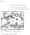
- the microstructure comprises a continuous phase and dispersed phase wherein the continuous phase is composed of CaCu 5 -type crystal structure and the dispersed phase is composed of three phases comprising Ce 2 Ni 7 -type crystal structure, rare earth element hydride which is a reaction product produced by the hydrogen heat treatment of the Ce 2 Ni 7 -type crystal structure and CaCu 5 -type crystal structure, and the dispersed phase of the CaCu 5 -type crystal structure is interposed in between the Ce 2 Ni 7 -type crystal structure and rare earth element hydride both of which are dispersed phases; and
- the maximum discharge capacity is greatly increased by the high-rate initial activation treatment of the battery owing to the action of the Ce 2 Ni 7 -type crystal structure and CaCu 5 -type crystal structure both of which are the dispersed phases of the above-mentioned alloy, namely, a high maximum discharge capacity is provided to the battery as well as the high maximum discharge capacity which is increased is available at small number of charge/discharge cycles, and further, a high high-rate discharge capacity at low temperature is provided to the battery, and that, hydrogen absorption and hydrogen desorption proceed as quickly as in the conventional occluding alloy, which is contributed by the rare earth element hydride also composing a dispersed phase.
- Fig.1 is illustrating the result of microstructure observation (magnifications: 15000) of an alloy 2 of the present invention using a scanning electron microscope.
- the present invention has been achieved on the above-mentioned findings and is characterized by the following hydrogen occluding alloy used for a cathode of battery;
- the hydrogen occluding alloy of the present invention has a composition comprising;
- composition of the hydrogen occluding alloy is defined as mentioned above.
- These rare earth elements form a continuous phase of CaCu 5 -type crystal structure having a hydrogen absorbing function with Ni, and form rare earth element hydride which contributes to promoting a hydrogen adsorption/desorption speed and Ce 2 Ni 7 -type crystal structure which contributes to obtaining a high discharge capacity at small number of charge/discharge cycles by a high-rate initial activation treatment of a battery and increasing a high-rate discharge capacity at low temperature. Since a maximum discharge capacity is decreased when the content is less than 32% or over 38%, the content is defined to 32 to 38% and preferable is 33 to 35%.
- a Co component dissolves into the matrix and has effects which reduce expansion/shrinkage of volume during hydrogen absorption/desorption with the result of preventing the fine-pulverization of the alloy and prolonging its usable life when the Co content is less than 0.1%, the above-mentioned effects can not be achieved.
- the content when the content is over 17%, the number of charge/discharge cycles tends to increase which are required for attaining a maximum discharge capacity when the high-rate initial activation treatment is carried out. Accordingly, the content is defined to 0.1 to 17% and preferable is 6 to 12%.
- An Al component dissolves into the matrix and improves the corrosion resistance of the alloy.
- the content is less than 0.1%, the desired effect on corrosion resistance can not be achieved.
- the content exceeds 3.5%, a maximum discharge capacity and a high-rate discharge capacity at low temperature decrease. Accordingly, the content is defined to 0.1 to 3.5% and preferable is 1 to 2%.
- a Mn component dissolves into the matrix and has effects which decrease the equilibrium dissociation pressure of hydrogen and increase a maximum discharge capacity.
- the content is less than 0.5%, the desired effect on increasing the maximum discharge capacity is not available.
- the content exceeds 10%, the maximum discharge capacity tends to decrease. Accordingly, the content is defined to 0.5 to 10% and preferable is 3 to 8%.
- Hydrogen predominantly bonds to rare earth elements by hydrogen heat treatment at high temperature to form rare earth element hydride which contributes to increasing a hydrogen absorption and desorption speed.
- the content is less than 0.05%, the ratio of the formed rare earth element hydride is insufficient with result that the effect thereof is not enough.
- the content is over 0.2%, the ratio of the formed rare earth element hydride is excessive with the result that a relative ratio of CaCu 5 -type crystal structure is excessively decreased and a maximum discharge capacity tends to sharply decrease.
- the content is defined to 0.005 to 0.2% and preferably is 0.01 to 0.15%.
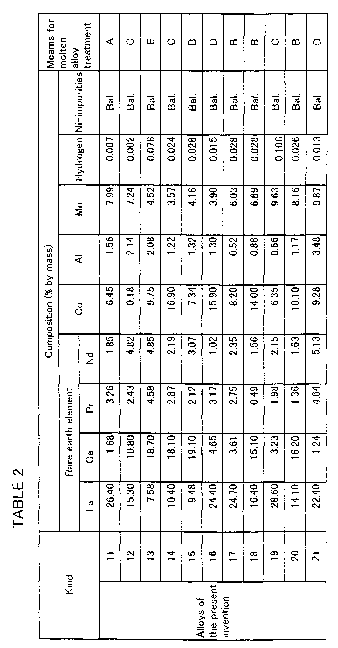
- Ni, La, Ce, Co, Al and Mn, further with a misch metal, as raw materials, each having a purity of at least 99.9% are melted in vacuum, using an ordinary high-frequency induction furnace, to prepare molten alloys each having a composition shown in Tables 1 to 3 and each molten metal is treated by any one of molten alloy treatments of (A) to (E) mentioned below.
- Each molten alloy is subjected to any one of the molten alloy treatments (the combination of each molten alloy with an applied treatment is shown in Tables 1 to 3) to form a hydrogen occluding alloy material having a prescribed shape.
- a material is inserted into a furnace for heat treatment and the following treatments are carried out: first, when a hydrogen heat treatment is carried out, heating up from room temperature to a prescribed temperature of within the range of 393 to 673K (120 to 400°C) is carried out in a vacuum condition of 0.13Pa (10 -3 Torr) to form an alloy having a microstructure in which a phase having a Ca 2 Ni 7 type crystal structure is dispersively distributed in a matrix having a CaCu 5 -type crystal structure; subsequently, after changing the vacuum atmosphere mentioned above to a hydrogen atmosphere having a prescribed pressure of within the range of 0.11 to 1.01MPa (1.1 to 10bar),
- pulverizing by a hydrogenation process is carried out which comprised hydrogen absorbing at a prescribed temperature of with of 283 to 473K (10 to 200°C) during the above-mentioned cooling process, followed by hydrogen desorption by vacuum exhausting, to thereby obtain the powder of each alloy having a particle size of up to 75 ⁇ m (200mesh).
- a hydrogen heat treatment is carried out in the same manner as in the above-mentioned cases except for excluding the pulverizing by a hydrogenation process.
- the powder obtained by the E method the powder is subjected to particle size control by sieving to obtain powder having a particle size of up to 75 ⁇ m (200mesh).
- the hydrogen occluding alloys Nos.1 to 32 of the present invention (referred to the alloy(s) of the present invention, hereinafter) are produced by the above-mentioned processes.
- the conventional hydrogen occluding alloys Nos.1 to 10 are produced wherein hydrogen occluding alloy materials having a prescribed shape are made of molten alloys having a composition shown Table 4 by subjecting the molten alloys to any one of the molten alloy treatments of (A) to (E) in accordance with the combinations of the molten alloy treatments with the molten alloys as shown in Table 4.; and a hydrogen heat treatment to the hydrogen occluding alloy materials is carried out in the same manner as to the hydrogen occluding alloy materials of the present invention except that heating up is carried out to a prescribed temperature of within the range of 673 to 1273K (400 to 1000 °C) in a hydrogen atmosphere having a prescribed pressure of within the range of 0.11 to 1.01MPa (1.1 to 10bar), followed by holding at this temperature for 1 hour, and then, cooling is carried out to a temperature of 573K (300°C) or less.
- the conventional alloy(s) referred to as the conventional alloy(s), here
- the microstructure of all the alloys of the present invention Nos.1 to 32 comprised a continuous phase and dispersed phase wherein the continuous phase is composed of CaCu 5 -type crystal structure and the dispersed phase is composed of three phases comprising Ce 2 Ni,-type crystal structure, rare earth element hydride which is a reaction product produced by the hydrogen heat treatment of the Ce 2 Ni 7 -type crystal structure and CaCu 5 -type crystal structure, and the dispersed phase of the CaCu 5 -type crystal structure is interposed in between the Ce 2 Ni 7 -type crystal structure and rare earth element hydride both of which are dispersed phases, while the microstructure of all the conventional
- Copper(I) oxide (Cu 2 O) as a conductive agent, polytetrafluoroethylene (PTFE) as a binder and carboxymethyl cellulose (CMC) as a thickener are added to each alloy of the present invention Nos.1 to 32 and the conventional alloys Nos.1 to 10 to form a paste and the resultant paste is filled up into a commercially available sintered porous Ni plate having a porosity of 95%.
- the sintered porous plate is dried and pressed, and shaped into a plate of 30mm X 40mm having a thickness of 0.40 to 0.43mm.
- the amount of the filled active material powder is approximately 1.8g.
- a nickel thin plate for forming a lead is welded to a side of the shaped plate to form a negative electrode.
- a positive electrode is formed as follows; a paste is prepared from Ni(OH) 2 as an active material to which cobalt monoxide (CoO) as a conductive agent, polytetrafluoroethylene (PTFE) as a binder and carboxymethyl cellulose (CMC) as a thickener are added; the resultant paste is filled up into the above mentioned sintered porous Ni plate; then, the sintered porous plate is dried and pressed, and shaped into a plate of 30mm X 40mm having a thickness of 0.71 to 0.73mm; and a nickel thin plate is welded to a side of the shaped plate, thereby to form a positive electrode.
- CoO cobalt monoxide
- PTFE polytetrafluoroethylene
- CMC carboxymethyl cellulose
- a battery is fabricated as follows; the positive electrodes are disposed on both sides of the negative electrode each through a separator made of a polypropylene/polyethylene copolymer, and protective plates made of vinyl chloride are provided on the outer side of the positive electrodes in such a manner that the positive electrodes are integrally sandwiched in between the protective plates so as to prevent the omission of the active material from the outside of the positive electrodes; the integrated electrodes are inserted into a cell made of vinyl chloride; and an aqueous solution of KOH having a concentration of 28% as an electrolyte is poured into the cell, to thereby produce a battery.
- the above-mentioned battery is subjected to a charge/discharge treatment, that is an high-rate initial activation treatment, which comprised the following conditions;
- the above-mentioned charge/discharge is counted as one cycle and the charge/discharge is repeated.
- a discharge capacity is measured at 5, 10 and 15 cycles of the charge/discharge, and further the charge/discharge cycle is repeated until the discharge capacity showed no change to measure a critical discharge capacity.
- the above-mentioned critical discharge capacity is defined as a maximum discharge capacity and the results of the measurement are shown in Figs.5 and 6.
- carbonyl nickel as a conductive agent, polytetrafluoroethylene (PTFE) as a binder and carboxymethyl cellulose (CMC) as a thickener are added to each alloy of the present invention Nos.1 to 32 and the conventional alloys Nos.1 to 10 to form a paste and the resultant paste is filled up into a commercially available sintered porous Ni plate having a porosity of 95%.
- the sintered porous plate is dried and pressed, and shaped into a plate of 320mm X 31mm having a thickness of 0.40 to 0.43mm.
- the amount of the filled active material powder is approximately 10g.
- a nickel thin plate for forming a lead is welded to a side of the shaped plate to form a negative electrode.
- a positive electrode is formed as follows; a paste is prepared from Ni(OH) 2 as an active material to which cobalt monoxide (CoO) as a conductive agent, polytetrafluoroethylene (PTFE) as a binder and carboxymethyl cellulose (CMC) as a thickener are added; the resultant paste is filled up into the sintered porous Ni plate; then, the sintered porous plate is dried and pressed, and shaped into a plate of 295mm X 31mm having a thickness of 0.50 to 0.53mm; and a nickel thin plate is welded to a side of the shaped plate, thereby to form a positive electrode.
- CoO cobalt monoxide
- PTFE polytetrafluoroethylene
- CMC carboxymethyl cellulose
- the negative electrode is piled on the positive electrode through a separator made of a polypropylene/polyethylene copolymer and the piled electrodes are wound to form a swirl having a diameter of about 20.5mm.
- the swirl is put in a cylindrical receptacle made of Ni having a inside diameter of 21mm and an aqueous solution of potassium hydroxide having a concentration of 28% is poured into the cylindrical receptacle, followed by sealing, to thereby to produce a hermetically sealed cylindrical battery having a rated capacity of 2700mAh.
- the battery is further subjected to a charge having the following condition;
- the battery is left at room temperature (in a thermostatic chamber having a temperature of -15°C) for 5 hours and is confirmed to have been stable at -15°C.
- the thermostatic chamber having a temperature of -15 °C discharge is continued under a discharge speed of 2C which is a quick discharge condition until the terminated voltage of discharge reached 0.9V and the discharge capacity thereof (referred to as high-rate discharge capacity at low temperature, hereinafter) is measured.
- the results of the measurement are also shown in Tables 5 and 6.
- the maximum discharge capacity is greatly increased by the high-rate initial activation treatment of the battery owing to the action of the Ce 2 Ni,-type crystal structure and CaCu 5 -type crystal structure both of which are the dispersed phases of the above-mentioned alloys, namely, a quite high discharge capacity is provided to the battery as well as the maximum discharge capacity which is greatly increased is available at small number of charge/discharge cycles, and further, a high-rate discharge capacity is available at a low temperature (-15 °C), whereas in batteries comprising the conventional alloys Nos.1 to 10, the maximum discharge capacity is relatively low , many number of charge/discharge cycles are required for attaining the maximum discharge capacity and a high-rate discharge capacity at low temperature is limited to a relatively low value.
- the hydrogen occluding alloys of the present invention when used as a cathode of battery, a high maximum discharge capacity is available by a high-rate initial activation treatment and further, a high-rate discharge capacity is available at a low temperature. Accordingly, the battery can be used for various mechanical equipment which require a high power, for examples, electric tools, electrically assisted bicycles and electric automobiles. Furthermore, as the battery exhibits a battery performance which enables the battery to be used at a low temperature and the high-rate initial activation treatment can be completed by small number of charge/discharge cycles, the alloys of the present invention are possessed of characteristics useful for industry which include contribution to providing to batteries a long life and a low cost.
Landscapes
- Chemical & Material Sciences (AREA)
- Chemical Kinetics & Catalysis (AREA)
- Electrochemistry (AREA)
- General Chemical & Material Sciences (AREA)
- Battery Electrode And Active Subsutance (AREA)
Abstract
Description
wherein the hydrogen occluding alloy enables to provide to the battery a high discharge capacity at small number of charge/discharge cycles by a high-rate initial activation treatment and to increase a high-rate discharge capacity at low temperature.


| Kind | Allowable maximum discharge capacity of battery in high-rate initial activation treatment (mAh/g) | Discharge capacity (mAh/g) | High-rate discharge cpacity at low temperature (m/Ah) | |||
| Number of charge/disharge: 5cycles | Number of charge/disharge: 10cycles | Number of charge/disharge: 15cycles | ||||
| Alloys of the present invention | 1 | 188 | 92 | 174 | 182 | 2350 |
| 2 | 205 | 119 | 176 | 200 | 2510 | |
| 3 | 189 | 99 | 177 | 184 | 2390 | |
| 4 | 179 | 94 | 155 | 175 | 2316 | |
| 5 | 178 | 89 | 159 | 171 | 2311 | |
| 6 | 165 | 88 | 146 | 159 | 2288 | |
| 7 | 205 | 116 | 192 | 199 | 2411 | |
| 8 | 192 | 109 | 177 | 182 | 2467 | |
| 9 | 179 | 87 | 155 | 174 | 2301 | |
| 10 | 180 | 84 | 156 | 175 | 2334 | |
| 11 | 161 | 65 | 152 | 156 | 2200 | |
| 12 | 151 | 88 | 136 | 147 | 2198 | |
| 13 | 203 | 117 | 179 | 198 | 2471 | |
| 14 | 182 | 84 | 166 | 179 | 2384 | |
| 15 | 185 | 101 | 176 | 180 | 2332 | |
| 16 | 174 | 79 | 162 | 168 | 2320 | |
| 17 | 185 | 84 | 172 | 179 | 2353 | |
| 18 | 185 | 89 | 158 | 181 | 2290 | |
| 19 | 207 | 108 | 195 | 202 | 2431 | |
| 20 | 177 | 75 | 155 | 173 | 2318 | |
| 21 | 182 | 88 | 155 | 177 | 2431 | |
| 22 | 191 | 82 | 167 | 184 | 2340 |
| Kind | Allowable maximum of battery in high-rate initial activation treatment (mAh/g) | Discharge capacity (mAh/g) | High-rate discharge cpacity at low temperature (m/Ah) | |||
| Number of charge/disharge: 5cycles | Number of charge/disharge: 10cycles | Number of charge/disharge: 15cycles | ||||
| Alloys of the present invention | 23 | 206 | 84 | 192 | 201 | 2463 |
| 24 | 171 | 69 | 157 | 165 | 2326 | |
| 25 | 176 | 72 | 166 | 172 | 2361 | |
| 26 | 199 | 94 | 177 | 191 | 2335 | |
| 27 | 196 | 85 | 168 | 189 | 2393 | |
| 28 | 173 | 98 | 158 | 169 | 2308 | |
| 29 | 183 | 100 | 163 | 177 | 2364 | |
| 30 | 178 | 89 | 159 | 174 | 2262 | |
| 31 | 185 | 83 | 166 | 180 | 2365 | |
| 32 | 184 | 85 | 166 | 180 | 2378 | |
| The conventional alloys | 1 | 125 | 8 | 40 | 97 | 1075 |
| 2 | 136 | 22 | 34 | 102 | 1197 | |
| 3 | 141 | 13 | 43 | 101 | 1318 | |
| 4 | 145 | 12 | 41 | 116 | 1313 | |
| 5 | 126 | 10 | 38 | 88 | 1235 | |
| 6 | 100 | 13 | 34 | 71 | 1003 | |
| 7 | 127 | 14 | 38 | 95 | 1271 | |
| 8 | 105 | 10 | 30 | 84 | 1079 | |
| 9 | 109 | 10 | 33 | 82 | 1050 | |
| 10 | 111 | 5 | 28 | 79 | 1118 |
Claims (1)
- A hydrogen occluding alloy used for a cathode of battery which comprises;and has a microstructure obtained by X-ray diffraction and microstructure observation with scanning electron microscope, said microstructure comprising a continuous phase and dispersed phase wherein the continuous phase is composed of CaCu5-type crystal structure and the dispersed phase is composed of three phases comprising Ce2Ni7-type crystal structure, rare earth element hydride which is a reaction product produced by the hydrogen heat treatment of the Ce2Ni7-type crystal structure and CaCu5-type crystal structure, and the dispersed phase of the CaCu5-type crystal structure is interposed in between the Ce2Ni7-type crystal structure and rare earth element hydride both of which are dispersed phases, wherein the hydrogen occluding alloy enables to provide to the battery a high discharge capacity at small number of charge/discharge cycles by a high-rate initial activation treatment and to increase a high-rate discharge capacity at low temperature.32 to 38% of rare earth elements mainly comprising La and/or Ce,0.1 to 17% of Co,0.1 to 3.5 % of Al,0.5 to 10 % of Mn and0.005% to 0.2% of hydrogen, with the balance being Ni and inevitable impurities,
Applications Claiming Priority (4)
| Application Number | Priority Date | Filing Date | Title |
|---|---|---|---|
| JP36689299 | 1999-12-24 | ||
| JP36689299 | 1999-12-24 | ||
| JP2000030091A JP3697996B2 (en) | 1999-12-24 | 2000-02-08 | Hydrogen storage alloy for battery negative electrode that enables high discharge capacity with a small number of charge / discharge cycles and improvement of low-temperature, high-rate discharge capacity with high-rate initial activation treatment |
| JP2000030091 | 2000-02-08 |
Publications (2)
| Publication Number | Publication Date |
|---|---|
| EP1113513A2 true EP1113513A2 (en) | 2001-07-04 |
| EP1113513A3 EP1113513A3 (en) | 2001-11-28 |
Family
ID=26581845
Family Applications (1)
| Application Number | Title | Priority Date | Filing Date |
|---|---|---|---|
| EP00126541A Withdrawn EP1113513A3 (en) | 1999-12-24 | 2000-12-11 | Hydrogen occluding alloy for battery cathode |
Country Status (4)
| Country | Link |
|---|---|
| US (1) | US20010007638A1 (en) |
| EP (1) | EP1113513A3 (en) |
| JP (1) | JP3697996B2 (en) |
| CN (1) | CN1171334C (en) |
Cited By (1)
| Publication number | Priority date | Publication date | Assignee | Title |
|---|---|---|---|---|
| ITUB20159317A1 (en) * | 2015-12-28 | 2017-06-28 | Guarniflon S P A | METHOD OF MANUFACTURING A FORMULATION AND FORMULATION |
Families Citing this family (6)
| Publication number | Priority date | Publication date | Assignee | Title |
|---|---|---|---|---|
| JP4706163B2 (en) * | 2003-03-14 | 2011-06-22 | 株式会社Gsユアサ | Hydrogen storage alloy electrode and nickel metal hydride storage battery using the same |
| JP5105766B2 (en) * | 2006-04-25 | 2012-12-26 | 三洋電機株式会社 | Alkaline storage battery, method for manufacturing the same, and assembled battery device |
| JP5529562B2 (en) * | 2010-01-29 | 2014-06-25 | 三菱重工業株式会社 | Method for producing hydrogen storage metal or hydrogen storage alloy |
| US8901888B1 (en) | 2013-07-16 | 2014-12-02 | Christopher V. Beckman | Batteries for optimizing output and charge balance with adjustable, exportable and addressable characteristics |
| JP6331824B2 (en) * | 2013-08-30 | 2018-05-30 | 三菱マテリアル株式会社 | Copper alloy sputtering target |
| CN111180718A (en) * | 2019-12-31 | 2020-05-19 | 深圳拓量技术有限公司 | Hydrogen storage alloy powder of nickel-hydrogen battery for ultralow temperature environment and preparation method thereof |
Family Cites Families (5)
| Publication number | Priority date | Publication date | Assignee | Title |
|---|---|---|---|---|
| US5376474A (en) * | 1993-02-05 | 1994-12-27 | Sanyo Electric Co., Ltd. | Hydrogen-absorbing alloy for a negative electrode and manufacturing method therefor |
| JPH09209065A (en) * | 1994-11-07 | 1997-08-12 | Santoku Kinzoku Kogyo Kk | Age precipitation type rare earth metal-nickel alloy, its production, and nickel-hydrogen secondary battery negative pole |
| DE69704003T2 (en) * | 1996-05-09 | 2001-06-07 | Mitsubishi Materials Corp., Tokio/Tokyo | Hydrogen absorbing alloy, process for its manufacture and electrode |
| DE69839465D1 (en) * | 1997-03-28 | 2008-06-26 | Matsushita Electric Industrial Co Ltd | Negative electrode for alkaline batteries |
| EP0969110A3 (en) * | 1998-06-16 | 2000-01-19 | Mitsubishi Materials Corporation | Hydrogen occluding alloy |
-
2000
- 2000-02-08 JP JP2000030091A patent/JP3697996B2/en not_active Expired - Fee Related
- 2000-12-11 EP EP00126541A patent/EP1113513A3/en not_active Withdrawn
- 2000-12-14 US US09/735,650 patent/US20010007638A1/en not_active Abandoned
- 2000-12-23 CN CNB001206931A patent/CN1171334C/en not_active Expired - Fee Related
Cited By (2)
| Publication number | Priority date | Publication date | Assignee | Title |
|---|---|---|---|---|
| ITUB20159317A1 (en) * | 2015-12-28 | 2017-06-28 | Guarniflon S P A | METHOD OF MANUFACTURING A FORMULATION AND FORMULATION |
| EP3187280A1 (en) * | 2015-12-28 | 2017-07-05 | Guarniflon S.P.A. | Method for the manufacture of a formulation and formulation |
Also Published As
| Publication number | Publication date |
|---|---|
| EP1113513A3 (en) | 2001-11-28 |
| JP2001240927A (en) | 2001-09-04 |
| CN1314722A (en) | 2001-09-26 |
| US20010007638A1 (en) | 2001-07-12 |
| CN1171334C (en) | 2004-10-13 |
| JP3697996B2 (en) | 2005-09-21 |
Similar Documents
| Publication | Publication Date | Title |
|---|---|---|
| US6524746B2 (en) | Hydrogen absorbing alloy powder and process for producing same | |
| EP1113513A2 (en) | Hydrogen occluding alloy for battery cathode | |
| JP3604156B2 (en) | Electrochemical battery | |
| EP0806803B1 (en) | Hydrogen occluding alloy, process for its preparation and electrode | |
| US6083327A (en) | Hydrogen occluding alloy | |
| JPH1125964A (en) | Alkaline storage battery | |
| CA2295204A1 (en) | Hydrogen storage alloy | |
| JPH10265875A (en) | Hydrogen storage alloy, method for producing the same, and nickel-metal hydride secondary battery | |
| JPH0763007B2 (en) | Manufacturing method of hydrogen storage electrode | |
| JPH10259436A (en) | Hydrogen storage alloy, method for producing the same, and nickel-metal hydride secondary battery | |
| JPH10265888A (en) | Hydrogen storage alloy, method for producing the same, and nickel-metal hydride secondary battery | |
| WO1998054775A9 (en) | Hydrogen storage alloy | |
| JP4117918B2 (en) | Hydrogen storage alloy, manufacturing method thereof, and nickel metal hydride secondary battery | |
| KR100207618B1 (en) | Anode manufacturing method of secondary battery and secondary battery having same | |
| JPH08120364A (en) | Hydrogen storage alloy for battery, method for producing the same, and nickel-hydrogen secondary battery | |
| JPH10259445A (en) | Hydrogen storage alloy, method for producing the same, and nickel-metal hydride secondary battery | |
| JP3454780B2 (en) | Alkaline storage battery | |
| JPS62264557A (en) | Metal oxide-hydrogen battery | |
| JP3369148B2 (en) | Alkaline storage battery | |
| JP3369838B2 (en) | Hydrogen storage alloy electrode | |
| JP2000129379A (en) | Hydrogen storage alloy | |
| JPH06163039A (en) | Hydrogen storage alloy electrode | |
| JPH10102173A (en) | Hydrogen storage alloy, method for producing the same, and nickel-metal hydride secondary battery | |
| JPH1060565A (en) | Hydrogen storage alloy and nickel hydrogen secondary battery | |
| JPH1116599A (en) | Hydrogen storage alloy and nickel hydrogen secondary battery |
Legal Events
| Date | Code | Title | Description |
|---|---|---|---|
| PUAI | Public reference made under article 153(3) epc to a published international application that has entered the european phase |
Free format text: ORIGINAL CODE: 0009012 |
|
| AK | Designated contracting states |
Kind code of ref document: A2 Designated state(s): AT BE CH CY DE DK ES FI FR GB GR IE IT LI LU MC NL PT SE TR |
|
| AX | Request for extension of the european patent |
Free format text: AL;LT;LV;MK;RO;SI |
|
| PUAL | Search report despatched |
Free format text: ORIGINAL CODE: 0009013 |
|
| AK | Designated contracting states |
Kind code of ref document: A3 Designated state(s): AT BE CH CY DE DK ES FI FR GB GR IE IT LI LU MC NL PT SE TR |
|
| AX | Request for extension of the european patent |
Free format text: AL;LT;LV;MK;RO;SI |
|
| AKX | Designation fees paid | ||
| REG | Reference to a national code |
Ref country code: DE Ref legal event code: 8566 |
|
| STAA | Information on the status of an ep patent application or granted ep patent |
Free format text: STATUS: THE APPLICATION IS DEEMED TO BE WITHDRAWN |
|
| 18D | Application deemed to be withdrawn |
Effective date: 20020529 |