EP1113511A1 - Lithium secondary cell and its producing method - Google Patents
Lithium secondary cell and its producing method Download PDFInfo
- Publication number
- EP1113511A1 EP1113511A1 EP00902113A EP00902113A EP1113511A1 EP 1113511 A1 EP1113511 A1 EP 1113511A1 EP 00902113 A EP00902113 A EP 00902113A EP 00902113 A EP00902113 A EP 00902113A EP 1113511 A1 EP1113511 A1 EP 1113511A1
- Authority
- EP
- European Patent Office
- Prior art keywords
- cathode
- sintered material
- current collector
- lithium
- anode
- Prior art date
- Legal status (The legal status is an assumption and is not a legal conclusion. Google has not performed a legal analysis and makes no representation as to the accuracy of the status listed.)
- Withdrawn
Links
Images

Classifications
-
- H—ELECTRICITY
- H01—ELECTRIC ELEMENTS
- H01M—PROCESSES OR MEANS, e.g. BATTERIES, FOR THE DIRECT CONVERSION OF CHEMICAL ENERGY INTO ELECTRICAL ENERGY
- H01M4/00—Electrodes
- H01M4/02—Electrodes composed of, or comprising, active material
- H01M4/13—Electrodes for accumulators with non-aqueous electrolyte, e.g. for lithium-accumulators; Processes of manufacture thereof
- H01M4/131—Electrodes based on mixed oxides or hydroxides, or on mixtures of oxides or hydroxides, e.g. LiCoOx
-
- H—ELECTRICITY
- H01—ELECTRIC ELEMENTS
- H01M—PROCESSES OR MEANS, e.g. BATTERIES, FOR THE DIRECT CONVERSION OF CHEMICAL ENERGY INTO ELECTRICAL ENERGY
- H01M10/00—Secondary cells; Manufacture thereof
- H01M10/04—Construction or manufacture in general
-
- H—ELECTRICITY
- H01—ELECTRIC ELEMENTS
- H01M—PROCESSES OR MEANS, e.g. BATTERIES, FOR THE DIRECT CONVERSION OF CHEMICAL ENERGY INTO ELECTRICAL ENERGY
- H01M10/00—Secondary cells; Manufacture thereof
- H01M10/04—Construction or manufacture in general
- H01M10/0413—Large-sized flat cells or batteries for motive or stationary systems with plate-like electrodes
-
- H—ELECTRICITY
- H01—ELECTRIC ELEMENTS
- H01M—PROCESSES OR MEANS, e.g. BATTERIES, FOR THE DIRECT CONVERSION OF CHEMICAL ENERGY INTO ELECTRICAL ENERGY
- H01M10/00—Secondary cells; Manufacture thereof
- H01M10/04—Construction or manufacture in general
- H01M10/045—Cells or batteries with folded plate-like electrodes
-
- H—ELECTRICITY
- H01—ELECTRIC ELEMENTS
- H01M—PROCESSES OR MEANS, e.g. BATTERIES, FOR THE DIRECT CONVERSION OF CHEMICAL ENERGY INTO ELECTRICAL ENERGY
- H01M10/00—Secondary cells; Manufacture thereof
- H01M10/05—Accumulators with non-aqueous electrolyte
- H01M10/052—Li-accumulators
-
- H—ELECTRICITY
- H01—ELECTRIC ELEMENTS
- H01M—PROCESSES OR MEANS, e.g. BATTERIES, FOR THE DIRECT CONVERSION OF CHEMICAL ENERGY INTO ELECTRICAL ENERGY
- H01M10/00—Secondary cells; Manufacture thereof
- H01M10/05—Accumulators with non-aqueous electrolyte
- H01M10/058—Construction or manufacture
- H01M10/0583—Construction or manufacture of accumulators with folded construction elements except wound ones, i.e. folded positive or negative electrodes or separators, e.g. with "Z"-shaped electrodes or separators
-
- H—ELECTRICITY
- H01—ELECTRIC ELEMENTS
- H01M—PROCESSES OR MEANS, e.g. BATTERIES, FOR THE DIRECT CONVERSION OF CHEMICAL ENERGY INTO ELECTRICAL ENERGY
- H01M4/00—Electrodes
- H01M4/02—Electrodes composed of, or comprising, active material
- H01M4/04—Processes of manufacture in general
- H01M4/0402—Methods of deposition of the material
-
- H—ELECTRICITY
- H01—ELECTRIC ELEMENTS
- H01M—PROCESSES OR MEANS, e.g. BATTERIES, FOR THE DIRECT CONVERSION OF CHEMICAL ENERGY INTO ELECTRICAL ENERGY
- H01M4/00—Electrodes
- H01M4/02—Electrodes composed of, or comprising, active material
- H01M4/04—Processes of manufacture in general
- H01M4/0402—Methods of deposition of the material
- H01M4/0404—Methods of deposition of the material by coating on electrode collectors
-
- H—ELECTRICITY
- H01—ELECTRIC ELEMENTS
- H01M—PROCESSES OR MEANS, e.g. BATTERIES, FOR THE DIRECT CONVERSION OF CHEMICAL ENERGY INTO ELECTRICAL ENERGY
- H01M4/00—Electrodes
- H01M4/02—Electrodes composed of, or comprising, active material
- H01M4/04—Processes of manufacture in general
- H01M4/043—Processes of manufacture in general involving compressing or compaction
-
- H—ELECTRICITY
- H01—ELECTRIC ELEMENTS
- H01M—PROCESSES OR MEANS, e.g. BATTERIES, FOR THE DIRECT CONVERSION OF CHEMICAL ENERGY INTO ELECTRICAL ENERGY
- H01M4/00—Electrodes
- H01M4/02—Electrodes composed of, or comprising, active material
- H01M4/04—Processes of manufacture in general
- H01M4/0471—Processes of manufacture in general involving thermal treatment, e.g. firing, sintering, backing particulate active material, thermal decomposition, pyrolysis
-
- H—ELECTRICITY
- H01—ELECTRIC ELEMENTS
- H01M—PROCESSES OR MEANS, e.g. BATTERIES, FOR THE DIRECT CONVERSION OF CHEMICAL ENERGY INTO ELECTRICAL ENERGY
- H01M4/00—Electrodes
- H01M4/02—Electrodes composed of, or comprising, active material
- H01M4/13—Electrodes for accumulators with non-aqueous electrolyte, e.g. for lithium-accumulators; Processes of manufacture thereof
- H01M4/139—Processes of manufacture
- H01M4/1391—Processes of manufacture of electrodes based on mixed oxides or hydroxides, or on mixtures of oxides or hydroxides, e.g. LiCoOx
-
- H—ELECTRICITY
- H01—ELECTRIC ELEMENTS
- H01M—PROCESSES OR MEANS, e.g. BATTERIES, FOR THE DIRECT CONVERSION OF CHEMICAL ENERGY INTO ELECTRICAL ENERGY
- H01M4/00—Electrodes
- H01M4/02—Electrodes composed of, or comprising, active material
- H01M2004/021—Physical characteristics, e.g. porosity, surface area
-
- H—ELECTRICITY
- H01—ELECTRIC ELEMENTS
- H01M—PROCESSES OR MEANS, e.g. BATTERIES, FOR THE DIRECT CONVERSION OF CHEMICAL ENERGY INTO ELECTRICAL ENERGY
- H01M4/00—Electrodes
- H01M4/02—Electrodes composed of, or comprising, active material
- H01M2004/026—Electrodes composed of, or comprising, active material characterised by the polarity
- H01M2004/028—Positive electrodes
-
- H—ELECTRICITY
- H01—ELECTRIC ELEMENTS
- H01M—PROCESSES OR MEANS, e.g. BATTERIES, FOR THE DIRECT CONVERSION OF CHEMICAL ENERGY INTO ELECTRICAL ENERGY
- H01M4/00—Electrodes
- H01M4/02—Electrodes composed of, or comprising, active material
- H01M4/36—Selection of substances as active materials, active masses, active liquids
- H01M4/48—Selection of substances as active materials, active masses, active liquids of inorganic oxides or hydroxides
- H01M4/50—Selection of substances as active materials, active masses, active liquids of inorganic oxides or hydroxides of manganese
- H01M4/505—Selection of substances as active materials, active masses, active liquids of inorganic oxides or hydroxides of manganese of mixed oxides or hydroxides containing manganese for inserting or intercalating light metals, e.g. LiMn2O4 or LiMn2OxFy
-
- H—ELECTRICITY
- H01—ELECTRIC ELEMENTS
- H01M—PROCESSES OR MEANS, e.g. BATTERIES, FOR THE DIRECT CONVERSION OF CHEMICAL ENERGY INTO ELECTRICAL ENERGY
- H01M4/00—Electrodes
- H01M4/02—Electrodes composed of, or comprising, active material
- H01M4/36—Selection of substances as active materials, active masses, active liquids
- H01M4/48—Selection of substances as active materials, active masses, active liquids of inorganic oxides or hydroxides
- H01M4/52—Selection of substances as active materials, active masses, active liquids of inorganic oxides or hydroxides of nickel, cobalt or iron
- H01M4/525—Selection of substances as active materials, active masses, active liquids of inorganic oxides or hydroxides of nickel, cobalt or iron of mixed oxides or hydroxides containing iron, cobalt or nickel for inserting or intercalating light metals, e.g. LiNiO2, LiCoO2 or LiCoOxFy
-
- Y—GENERAL TAGGING OF NEW TECHNOLOGICAL DEVELOPMENTS; GENERAL TAGGING OF CROSS-SECTIONAL TECHNOLOGIES SPANNING OVER SEVERAL SECTIONS OF THE IPC; TECHNICAL SUBJECTS COVERED BY FORMER USPC CROSS-REFERENCE ART COLLECTIONS [XRACs] AND DIGESTS
- Y02—TECHNOLOGIES OR APPLICATIONS FOR MITIGATION OR ADAPTATION AGAINST CLIMATE CHANGE
- Y02E—REDUCTION OF GREENHOUSE GAS [GHG] EMISSIONS, RELATED TO ENERGY GENERATION, TRANSMISSION OR DISTRIBUTION
- Y02E60/00—Enabling technologies; Technologies with a potential or indirect contribution to GHG emissions mitigation
- Y02E60/10—Energy storage using batteries
-
- Y—GENERAL TAGGING OF NEW TECHNOLOGICAL DEVELOPMENTS; GENERAL TAGGING OF CROSS-SECTIONAL TECHNOLOGIES SPANNING OVER SEVERAL SECTIONS OF THE IPC; TECHNICAL SUBJECTS COVERED BY FORMER USPC CROSS-REFERENCE ART COLLECTIONS [XRACs] AND DIGESTS
- Y02—TECHNOLOGIES OR APPLICATIONS FOR MITIGATION OR ADAPTATION AGAINST CLIMATE CHANGE
- Y02P—CLIMATE CHANGE MITIGATION TECHNOLOGIES IN THE PRODUCTION OR PROCESSING OF GOODS
- Y02P70/00—Climate change mitigation technologies in the production process for final industrial or consumer products
- Y02P70/50—Manufacturing or production processes characterised by the final manufactured product
-
- Y—GENERAL TAGGING OF NEW TECHNOLOGICAL DEVELOPMENTS; GENERAL TAGGING OF CROSS-SECTIONAL TECHNOLOGIES SPANNING OVER SEVERAL SECTIONS OF THE IPC; TECHNICAL SUBJECTS COVERED BY FORMER USPC CROSS-REFERENCE ART COLLECTIONS [XRACs] AND DIGESTS
- Y10—TECHNICAL SUBJECTS COVERED BY FORMER USPC
- Y10T—TECHNICAL SUBJECTS COVERED BY FORMER US CLASSIFICATION
- Y10T29/00—Metal working
- Y10T29/49—Method of mechanical manufacture
- Y10T29/49002—Electrical device making
- Y10T29/49108—Electric battery cell making
-
- Y—GENERAL TAGGING OF NEW TECHNOLOGICAL DEVELOPMENTS; GENERAL TAGGING OF CROSS-SECTIONAL TECHNOLOGIES SPANNING OVER SEVERAL SECTIONS OF THE IPC; TECHNICAL SUBJECTS COVERED BY FORMER USPC CROSS-REFERENCE ART COLLECTIONS [XRACs] AND DIGESTS
- Y10—TECHNICAL SUBJECTS COVERED BY FORMER USPC
- Y10T—TECHNICAL SUBJECTS COVERED BY FORMER US CLASSIFICATION
- Y10T29/00—Metal working
- Y10T29/49—Method of mechanical manufacture
- Y10T29/49002—Electrical device making
- Y10T29/49108—Electric battery cell making
- Y10T29/49114—Electric battery cell making including adhesively bonding
Definitions
- the present invention relates to a lithium secondary battery comprising a cathode made by sintering a lithium-transition metal oxide and having a high battery capacity and excellent charge/discharge cycle characteristic, and a method of producing the same.
- the lithium secondary battery comprises a cathode and an anode both including an active material capable of incorporating and releasing lithium ions, and a lithium ion conductive electrolytic solution or solid electrolyte.
- the electrode includes such materials as a binder and an electrically conductive material that do not contribute to the battery capacity, thus resulting in a limitation to the capacity per volume of the battery.
- an attempt to make the electrode from a sintered material which is substantially made of an active material.
- the electrode is constituted from a sintered material made of an active material, no binder is included and the addition of an electrically conductive material can be eliminated or reduced, thus making it possible to increase the active material filling density and increase the capacity per volume.
- Japanese Laid-Open Patent Publication No.8-180904 discloses a cathode made of a sintered lithium-transition metal oxide.
- powder of a lithium-transition metal oxide or raw material powder thereof is pressed to form a molded material by using a die, with the mold material being fired at a predetermined temperature in the presence of oxygen, thereby to obtain a sintered material.
- an electrical conductivity of the sintered material is not sufficient for the cathode, and therefore it is necessary to improve the performance further.
- the lithium secondary battery thinner, it is effective to reduce the thickness of the cathode and the anode that make up most of the thickness of the battery.
- increasing the area of the die for the purpose of increasing the surface area of the sintered material makes it difficult to fill the cavity of the die uniformly with the powder of lithium-transition metal oxide or raw material powder thereof, resulting in unevenness of the thickness and a density of the molded material in a planer direction.
- Japanese Laid-Open Patent Publication No.8-180904 described above discloses a method of decreasing the contact resistance by sintering the powder of a lithium-transition metal oxide or raw material powder of a lithium-transition metal oxide and, at the same time, integrating the sintered material with a current collector of aluminum.
- the firing temperature cannot be made sufficiently high.
- the sintering process tends to be insufficient thus leading to lower strength and/or lower electrical conductivity of the sintered material, resulting in insufficient improvement in the charge/discharge cycle characteristic.
- the electrode cannot be wound as in the case of the conventional coated electrode because the sintered material has a low bending strength.
- both electrodes can be easily aligned with each other simply by stacking the cathode and the anode to oppose each other while interposing a separator therebetween.
- An object of the present invention is to provide a lithium secondary battery that, by providing a cathode of larger surface area and higher mechanical strength, has a large battery capacity and excellent charge/discharge cycle characteristic.
- Another object of the present invention is to provide a lithium secondary battery that, with a current collector being integrated with a sintered material of a lithium-transition metal oxide without lowering the mechanical strength and electrical conductivity thereof, has a large battery capacity and excellent charge/discharge cycle characteristic.
- Still another object of the present invention is to provide a lithium battery that comprises the electrode made of a plurality of sintered materials, where the cathodes and the anodes will not be shifted from the predetermined positions and high reliability is ensured.
- the present inventors completed the present invention by finding out that the electrical conductivity can be used as an index of the bonding strength between primary particles that constitute a sintered material when forming the sintered material of a lithium-transition metal oxide, and that sufficient mechanical strength can be obtained by using a sintered material having a high electrical conductivity.
- the lithium secondary battery of the present invention includes a cathode and an anode, each electrode containing an active material capable of storing and releasing lithium ions, wherein the cathode is a porous sintered material made of a lithium-transition metal oxide that has a porosity in a range from 15 to 60% and an electrical conductivity of more than 0.1 mS/cm.
- the porosity of the sintered material that constitutes the cathode is in a range from 15 to 60%, an electrolytic solution infiltrates sufficiently into the sintered material under such a condition that filling density of the active material is maintained at a high level. With this constitution, the internal electrical resistance can be decreased without decreasing the battery capacity.
- the cathode having the porosity in a range from 15 to 60% and the electrical conductivity of more than 0.1 mS/cm provides the battery with a large battery capacity and excellent charge/discharge cycle characlteristic.
- the sintered material and the current collector are integrated at a temperature lower than the melting point of the current collector, so that the current collector is not damaged by thermal deformation, and the contact resistance can be decreased. Consequently, strength and electrical conductivity of the sintered material are improved, and the cathode having lower contact resistance improves the charge/discharge cycle characteristic.
- the step of forming the sintered material includes a) adding a binder and a solvent to a cathode material consisting of the powder of a lithium-transition metal oxide, thereby to prepare a coating solution; b) applying the coating solution to a base material and removing the solvent to form the coating film; and c) firing the coating film in the presence of oxygen to sinter the cathode material, thereby to form the sintered material. Since the coating film containing the cathode material consisting of the powder of a lithium-transition metal oxide is fired to form the sintered material, the cathode having a larger surface area and, an uniformity in thickness and density can be obtained. The cathode can improve the battery capacity and cycle characteristic.
- the method of producing the lithium secondary battery according to the present invention is capable of forming the sintered material with a uniform thickness and pressing the sintered material to the current collector.
- the sintered material with uniform thickness makes it possible to press the current collector uniformly over the entire surface of the sintered material. As a result, adhesion between the sintered material and the current collector can be improved and the electrical contact resistance can be decreased without causing the sintered material to deform and crack when pressing.
- the lithium battery of the present invention is a battery comprising a stacked electrode formed of a multilayered electrode unit which includes cathodes and anodes piled via a separator and has strip-shaped current collector, wherein at least the cathodes are sintered materials which are aligned on and joined to one of the current collectors and spaced from one another at bending portions defined by desirable intervals on the current collector, and the cathodes and the anodes are disposed in the stacked electrode, with each anode opposed to the respective cathode.
- the cathodes and the anodes are accurately aligned so that the electrodes will not be shifted from the predetermined positions, and a current collection can be easily made since providing only one lead wire for each of the cathodes and the anodes suffices, and therefore a lithium secondary battery of high reliability can be achieved.
- the battery including the stacked electrode described above is produced by a method, which includes the step of forming at least a cathode electrode sheet, on at least one side of the strip-shaped current collector, having a plurality of sintered material electrodes aligned on and joined thereto and spaced from one another at bending portions defined by desirable intervals on the current collector; the step of bending the stack which includes the cathode electrode sheet and an anode electrode sheet piled via a separator so that each cathode oppose the respective anode; and the step of housing the stack in a battery casing.
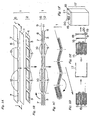
- Fig. 1A to 1F is a schematic sectional view showing a method of producing a battery A according to the third embodiment of the present invention.
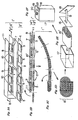
- Fig. 2A to 2F is a schematic sectional view showing a method of producing a battery B according to the third embodiment of the present invention.
- Fig. 3A to 3F is a schematic sectional view showing a method of producing a battery C according to the third embodiment of the present invention.
- the lithium secondary battery of the present invention comprises a stack body constituted from, for example, a cathode current collector, a cathode, a separator including a non-aqueous electrolytic solution or a non-aqueous electrolyte made of a polymer solid electrolyte, an anode, and an anode current collector.
- the cathode used in the present invention includes the lithium-transition metal oxide as a cathode active material.
- the lithium-transition metal oxide may be any conventionally known material.
- Li x CoO 2 , Li x NiO 2 , Li x MnO 2 , Li x Mn 2 O 4 , Li x Mn 2-y O 4 or the like may be used.
- As the compounds of lithium and the transition metal used as the raw material hydroxide, oxide, nitride and carbide of these metals may be used.
- the anode material used in the present invention includes such carbon materials as graphite, amorphous carbon or a mixture thereof, for example, such as a material made by carbonizing cokes, natural graphite, artificial graphite or pitch, and a mixture thereof.
- a sintered material made from a composite material of silicon and carbon material as described in International Publication WO98/24135 may be used.
- non-aqueous electrolytic solution prepared by dissolving a lithium compound such as LiPF 6 , as the electrolyte in an organic solvent such as ethylene carbonate or dimethyl carbonate, or a polymer solid electrolyte made of a polymer that holds a lithium compound in the state of solid solution or an organic solvent, wherein the lithium compound is dissolved, may be used.
- the sintered material of the lithium-transition metal oxide used in the present invention can be made as described below.
- Acoating solution is prepared by dispersing a powder of a lithium-transition metal oxide or a raw material powder of the lithium-transition metal oxide together with a binder in a solvent, then the coating solution is applied to a base material which is, after removing the solvent, fired to sinter in the presence of oxygen. It is more preferable to fire in the presence of oxygen after removing the solvent and peeling the coating film off the base material, since this prevents the coating film from warping during firing.
- a film or a sheet of an organic polymer or a metal foil or sheet may be used, while an organic polymer film is more preferable.
- the sintered material preferably has a size of 20 mm ⁇ 20 mm or larger, and more preferably 40 mm ⁇ 40 mm or larger
- the sintering temperature is such a level as the binder is completely oxidized and decomposed and the sintering reaction proceeds sufficiently, that is higher than the melting point of the current collector, in a range from 700 to 1100°C and preferably in a range from 800 to 1000 °C .
- Duration of sintering is from 0.1 to 100 hours, preferably from 1 to 50 hours.
- thermosetting resins such as urethane resin, phenol resin, and epoxy resin
- thermoplastic resins or elastomers such as polyethylene and polypropylene
- homopolymers or copolymers of containing a monomer such as vinylidene fluoride, ethylene fluoride, acrylonitrile, ethylene oxide, propylene oxide and methyl methacrylate
- polyvinyl alcohol or polyvinyl butyral there can be used thermosetting resins such as urethane resin, phenol resin, and epoxy resin
- thermoplastic resins or elastomers such as polyethylene and polypropylene
- homopolymers or copolymers of containing a monomer such as vinylidene fluoride, ethylene fluoride, acrylonitrile, ethylene oxide, propylene oxide and methyl methacrylate
- polyvinyl alcohol or polyvinyl butyral polyvinyl butyral
- a pore-forming agent In order to form communicating holes that are effective as the passage of ions, a pore-forming agent may be used.
- the pore-forming agent is a substance that is not soluble to the solvent used in the preparation of the coating solution, and may be a substance that is completely oxidized and decompose in air atmosphere at a temperature close to the thermal decomposition temperature of the binder, for example short fibers of organic materials (diameter from 0.1 to 100 ⁇ m) such as nylon fiber, acrylic fiber, acetate fiber and polyester fiber, or organic polymer particles such as polymethyl methacrylate (PMMA) having diameters from 0.1 to 100 ⁇ m.
- PMMA polymethyl methacrylate
- ion passages can be effectively formed Because a diffusion of the ions is not prevented, the ion passages can suppress a concentration polarization of ions, thereby to decrease the internal electrical resistance.
- the porosity of the cathode that is obtained is preferably in a range from 15 to 60%, and more preferably in a range from 30 to 50%.
- the porosity is lower than 15%, the electrolytic solution cannot infiltrate into the sintered material sufficiently, resulting in a high internal electrical resistance.
- the porosity is higher than 60%, filling density of the active material becomes lower and the desired battery capacity cannot be obtained.
- the porosity is an open pore . volume, and is measured on the basis of the Archimedean principle described below.
- Porosity can be determined by the following equation: where W 1 is an initial weight of a sample, W 2 is a weight measured in water after purging air from pores by decreasing the pressure or boiling in water and then cooling, and W 3 is a weight measured after being taken out of water and wiped to remove water drops on the surface, then the porosity is given as shown above.
- the electrical conductivity of the sintered material used in the cathode is preferably 0.1 mS/cm or higher, and more preferably 1 mS/cm or higher This increases the bonding strength between primary particles of the sintered material and improves the mechanical strength of the electrode.
- the sintered material of the lithium-transition metal oxide formed in the process described above and the current collector can be integrated as follows.
- the sintered material and the current collector are laminated under a pressure, and heated at a temperature lower than the melting point of the current collector.
- heating temperature is from 50 to 600°C, preferably from 100 to 300°C, while there is no particular limitation on the heating time as long as the duration is not less than one second. While there is no limitation on the ambience during heating, air atmosphere or non-oxidative atmosphere is preferable.
- the sintered material with a uniform thickness makes it possible that the current collector is pressed to the sintered material uniformly over the entire surface e thereof.
- the method described previously where the coating film is formed on the organic polymer film is preferable, but a method of polishing the surface of the sintered material may also be employed.
- the cathode current collector in the present invention aluminum, titanium or stainless steel, or an alloy that includes any of these may be used, while aluminum is preferable.
- This material may be in the form of either foil or mesh.
- a sintered material When a sintered material is used for the anode, it may be joined with the anode current collector by, for example, a method described below.
- the sintered material is pressed to the current collector and heated at a temperature lower than the melting point of the current collector.
- heating temperature is from 50 to 1000°C, while there is no particular limitation on the heating time as long as the duration is not less than one second.
- the ambiance during heating is preferably air atmosphere or non-oxidative atmosphere.
- a coating film including an active material may be formed on the current collector, which is then heated to sinter.
- a battery of the first embodiment was produced by a method described below.
- LiCoO 2 60 Parts by weight (hereinafter parts by weight are abbreviated to parts) of LiCoO 2 was mixed with 3.4 parts of polyvinyl butyral as a binder, 0.85 parts of dioctyl adipate as a plasticizer and 28 parts of a mixed solvent of toluene and 1-butyl alcohol in a volume ratio of 4:1, and the mixture was kneaded in a ball mill for 24 hours.
- This coating solution was applied to a polyester film having a thickness of 50 ⁇ m that had been treated with silicone, then the film was dried at 80°C for 20 minutes thereby to obtain a coating film having a size of 300 ⁇ 150 mm.
- the coating film was removed from the polyester film and was cut into pieces having a size of 30 ⁇ 40 mm, which were fired at 900°C in air atmosphere for 10 hours, thereby to obtain a sintered body of LiCoO 2 having a thickness of 300 ⁇ m ⁇ 3% and porosity of 41%.
- the shrinkage ratio after firing ⁇ 1 - (Length after firing/ Length before firing) was about 7%.
- the electrical conductivity of the sintered material was measured by the method described below. As a result, it was 13 mS/cm.
- the electrical conductivity of the sintered material was measured by the four-terminal method.
- Four leads were connected to the sintered material parallel to each other at a predetermined space from each other, with the outermost two leads used for supplying current and the innermost two leads used for measuring voltage, being connected to current source and a volt meter, respectively.
- voltage V was measured to determine the resistance R
- the sintered material was heated to 300°C, then cooled down to the room temperature, thereby to obtain a cathode integrated with the current collector.
- NMP N-methyl-2-pyrrolidone
- An electrolytic solution was prepared by dissolving 1 mol/L of LiPF 6 in a mixed solvent of propylene carbonate and dimethyl carbonate in a volume ratio of 1:1.
- the cathode and the anode described above were piled via a separator made of a porous polyethylene film, and the stack was put into a battery housing, with the battery housing being filled with the electrolytic solution and sealed, thereby making the battery.
- Sample No. 2 is a battery that employs a cathode made by the cathode forming method described above, except that 3 parts of spherical polymethyl methacrylate (PMMA) having a diameter of 5 ⁇ m was added as a pore forming agent to the coating solution.
- Sample No. 2 had a porosity of 43%.
- the shrinkage ratio of the sintered body after firing was about 7%, and the electrical conductivity was 5 mS/cm.
- the discharge capacity in the first cycle was 60 mAh and the capacity retention ratio in the fiftieth cycle was 90%.
- Sample No. 3 is a battery that employs a sintered material having a thickness of 300 ⁇ m ⁇ 3% and porosity of 43% made by the cathode forming method described above by firing at a temperature of 900°C for three hours in air atmosphere.
- the shrinkage ratio of the sintered body after firing was about 2%, and the electrical conductivity was 0.04 mS/cm.
- the discharge capacity in the first cycle was 60 mAh and the capacity retention ratio in the fiftieth cycle was 10%.
- Sample No.4 employed a molded material instead of a coating film in forming the cathode. 10 Parts of polyethylene powder was added as an auxiliary forming agent to 100 parts of LiCoO 2 powder Although it was attempted to press the mixture in a die to make a molded material having a size of 20 ⁇ 40 mm, the powder could not be packed uniformly and the molded material could not be made.
- Batteries according to the second embodiment were produced by the following method.
- Spherical PMMA particles having a mean particle diameter of 5 ⁇ m was mixed as a pore-forming agent by 5wt% to the calcinated powder, with the mixed powder being pressed into a molded material which was fired at a temperature of 900°C for 10 hours in air atmosphere, thereby to obtain a pellet-shaped sintered material of 19 mm in diameter and 94 ⁇ m in thickness, having a density of 3.0 g/cm 3 and porosity of 41%.
- the electrical conductivity of this sintered material was 5 mS/cm.
- the cathode was heated to 300°C. After cooling down the cathode to the room temperature, peel-off test was conducted to make sure that the aluminum foil and the sintered material were integrated.
- the cathode integrated with a current collector, the anode and a porous polyethylene film were stacked so that the active material surfaces of both electrodes face each other via the porous polyethylene film, and the laminate was immersed in an electrolytic solution that was prepared by dissolving LiPF 6 in a mixed solvent of ethylene carbonate and dimethyl carbonate in a volume ratio of 1:1, with the concentration being adjusted to 1 mol/L, thereby making the battery of sample No.5.
- Charge/discharge test was conducted under the following conditions. Current, upper limit of voltage and charging period of constant current-constant voltage charging were set to 4 mA, 4.1 V and 3 hours, while current and lower limit of voltage of constant current discharging were set to 2.6 mA and 2.5 V, respectively. Charging and discharging operations were repeated for 50 cycles, and the charge and discharge capacities were measured.
- Sample No. 6 is a battery that employs cathode made by the method described below.
- 100 Parts of the calcinated powder and 8 parts of polyvinylidene fluoride were mixed in NMP thereby to prepare a coating solution. The coating solution was applied to an aluminum foil having a thickness of 14 ⁇ m and dried.
- the dried film was punched through to obtain a pellet having a size of 19 mm in diameter, that was pressed to an aluminum foil and heated to 500°C thereby to fire the coating film and integrate it with the aluminum foil.
- the sintered material thus obtained was 100 ⁇ m in thickness, and had a density of 3.0 g/cm 3 and a porosity of 41%.
- sample No. 6 has cathode sintered and integrated with . the current collector simultaneously.
- Sample No. 5 has cathode formed by integrating the sintered material made by sintering at 900°C, higher than the melting point of the aluminum foil of the current collector, and the current collector at 300°C, lower than the melting point of the current collector.
- the initial charging capacity of sample No. 6 was 25% that of samples No. 5.
- the initial charge/discharge efficiency was 98% with sample No. 5 and 20% with sample No. 6.
- the discharge capacity in the 50th cycle was 93% of the initial charge capacity with the sample No. 5, while that of the sample No. 6 was 0% which meant that charging and discharging were impossible.
- the discharge voltage of the sample No.5 did not change after repeating 50 cycles of charge and discharge, the sample No. 6 showed a decrease in the discharge voltage.
- the cathode of the sample No. 5 showed a high strength and a high electrical conductivity, and larger battery capacity and better cycle characteristic than the sample No. 6.
- Fig. 1A-1F, Fig. 2A-2F and Fig. 3A-3F show schematic sectional views of processes for producing the lithium secondary batteries according to this embodiment of the present invention.
- the secondary battery of this embodiment includes a stack formed of a multilayered electrode unit that includes cathodes and anodes piled via a separator and has strip-shaped current collectors.
- Fig. 1A-1F shows a battery A having a stacked electrode formed by folding a multilayered electrode unit
- Fig. 2A-2F shows a battery B having a stacked electrode formed by winding a multilayered electrode unit
- Fig. 3A-3F shows a battery C having a stacked electrode formed by folding the multilayered electrode unit in a different way from the battery A.
- Fig. 1A is a perspective view showing the structure of a multilayered electrode unit 1.
- the multilayered unit 1 comprises a cathode sheet 2 and an anode sheet 6 that oppose each other via a separator 11.
- the cathode sheet 2 comprises a strip-shaped cathode current collector 4 and a plurality of cathodes 3 made of sintered material aligned on and joined to one side of thereof The plurality of cathodes 3 are joined while being spaced from one another at a plurality of bending portions 5 that secure spaces required for bending and are defined by desirable intervals on the cathode current collector 4.
- the anode sheet 6 has a structure similar to that of the cathode 2, including a strip-shaped anode current collector 8 and a plurality of anodes 7 made of sintered material aligned on and joined to one side of thereof, the plurality of anodes 7 being joined while being spaced from one another at a plurality of bending portions 10 defined by desirable intervals on the anode current collector 8.
- one end of the strip-shaped anode current collector 8 is stretched in the longitudinal direction to form the anode lead 9.
- the spaces of the bending portion 5 on the cathode side and the bending portion 10 on the anode side are made substantially equal to each other.
- the space of the bending portion of the electrode sheet on the outside of bending should ideally be made larger by the amount of thickness of the multilayered electrode unit However, since the size of the width of the electrode is 10 mm or larger in contrast to the multilayered electrode unit having thickness of about several hundreds of micrometers, the space of the bending portion may be made substantially the same.
- the multilayered electrode unit 1 can be made so that all cathodes 3 and the anodes 7 oppose each other as shown in Fig. 1B.
- Fig. 1B is a sectional view taken along lines I-T of Fig. 1A. Then the multilayered electrode unit 1 is folded by alternately folding up and folding back at the bending portions 5 and the bending portions 10 as shown in Fig. 1C, so that the adjacent cathodes 3 oppose each other and the adjacent anodes 7 oppose each other.
- a stacked electrode 15 is formed by completely folding the multilayered electrode unit 1(Fig. 1D). Then the anode lead 9 that extends from the front end of the stacked electrode 15 is welded onto an anode terminal 20 via an insulation plate 16, while the stacked electrode 15 is housed in a can 17 so that the rear end of the stacked electrode 15 and the cathode current collector on the outermost layer are brought into contact with the bottom and wall surfaces of the can 17 (Fig. 1E). Then the can 17 is sealed with a lid 18 that has a gas purging hole 21 and welded by laser. After filling the can with a non-aqueous electrolytic solution in a non-aqueous environment, the can is sealed to complete the battery (Fig. 1F). The anode terminal 20 is fastened onto the lid 18 via insulating packing 19.
- Fig. 2A-2F shows the process of producing the battery B. Processes other . than those shown in Fig. 2A to 2E and the formation of the electrodes can be done similar to the process of producing the battery A.
- Fig. 2A is a perspective view showing the structure of a multi-layered unit 1'.
- a cathode sheet 2' and an anode sheet 6' have a plurality of cathodes 3 and a plurality of anodes 7, both made of the sintered material, being joined on both sides thereof.
- An end of the cathode sheet 2' is located on the outermost layer after being wound, and therefore the cathode may be joined only on one side of the cathode current collector 4.
- Fig. 2B is a sectional view taken along lines II-IT of Fig. 2A. Then the multilayered electrode unit 1' is bent at the bending portions 5', . 10' as shown in Fig.
- the battery B has the plurality of cathodes and the plurality of anodes on both sides of the cathode sheet and the anode sheet, respectively, the amount of the active material contained can be made larger than the case of providing the cathodes or the anodes only on one side, thus achieving a higher energy density of the battery.
- Fig. 3A-3F shows a process of producing the battery C.
- Fig. 3A is a perspective view showing the structure of the cathode sheet 2
- Fig. 3B is a sectional view taken along lines III-III' of Fig. 3A.
- a pair of anodes which are joined on one side thereof to the anode current collector 8', are placed on the cathode 3 at the end of the cathode sheet 2.
- the cathode sheet 2 includes the strip-shaped cathode current collector 4 and a plurality of cathodes 3 formed on one side thereof from the sintered material.
- the plurality of cathodes 3 are joined while being separated by a plurality of bending portions 5 that provide spaces necessary for bending.
- the cathode sheet 2 is folded on the bending portion at the end so that the adjacent cathodes 3 hold therebetween a pair of anodes 7 that are placed on the cathode 3 via the separator 11. Then the cathode sheet 2 and the separator 11 are folded back at the bending portion 5 so that the adjacent cathodes 3 opposes each other (Fig. 3B, 3C). This operation is repeated a plurality of times to fold up the cathode sheet 2, so that the cathodes and the anodes oppose each other, thereby to form the stacked electrode 15 (Fig. 3D).
- a pair of anodes 7 made of the sintered material joined onto a rectangular anode current collector 8' may be used.
- the anode current collector 8' has the strip-shaped anode lead 9 that protrudes at one end therof.
- the plurality of anode leads 9 extending from the front end of the stacked electrode 15 is bundled into an anode-connecting conductor 12 (Fig. 3D).
- the anode connecting conductor 12 is welded onto the anode terminal 20 via an insulation plate 16, while the stacked electrode 15 is housed in the can 17 so that the rear end of the stacked electrode 15 and the cathode current collector on the outermost layer make contact with the bottom and the wall of the can 17 (Fig. 1E).
- the subsequent process to complete the battery is similar to the case of the first embodiment (Fig. 3F).
- An anode sheet that includes a plurality of anodes made of sintered material may be used instead of the cathode sheet, and sintered cathodes may be used instead of the sintered anodes.
- the electrodes can be aligned easily and displacement of the electrodes can be prevented.
- the anodes 7 may also be constituted from coating film electrodes.
- a heat treatment at a high temperature is not necessary unlike the case of forming the sintered electrodes. Therefore, the electrodes can be formed more easily than the case where the sintered material is used for the cathodes and the anodes.
- the coating film electrode may be a strip-shaped current collector coated with a coating solution containing the active material and a binder, which is then dried to integrate therewith.
- a coating film that includes a compound of silicon and a carbon material or a carbon material as the anode active material may be used.
- Two anode coating films were formed similarly to the anode of the first embodiment, being spaced from one another at bending portion substantially the same space as the bending portion of the cathode, and were fired at 800°C in nitrogen atmosphere for 3 hours, thereby to form an anode sheet.
- the cathode and the anode were piled via a separator made of .porous polyethylene film thereby to form a multilayered electrode unit.
- the multilayered electrode unit was folded at the bending portions to make the stacked electrode.
- an insulating film By covering the stacked electrode with an insulating film, a battery element was made.
- the battery element was put into a square battery can which was filled with an electrolytic solution prepared by adding 1 mol/L of LiPF 6 to a mixed solvent of ethylene carbonate and dimethyl carbonate in a volume ratio of 1:1. The battery can was sealed thereby completing the battery.
- the lithium secondary battery of the present invention employs the cathode including the porous sintered material made from the lithium-transition metal oxide with a porosity in a range from 15 to 60% and the electrical conductivity of more than 0.1 mS/cm, as described above, the cathode has higher mechanical strength. Also because the internal electrical resistance of the battery is decreased, the battery has larger capacity and excellent cycle characteristic.
- the cathode made of the material sintered at a temperature higher than the melting point of the current collector is heated to a temperature lower than the melting point of the current collector thereby to integrate with the current collector, strength and electrical conductivity of the cathode can be improved and, at the same time, contact resistance can be decreased without damaging the current collector by thermal deformation.
- the lithium secondary battery having larger capacity and excellent cycle characteristic is provided.
- the method of producing the lithium secondary battery of the present invention also makes it possible to form the cathode having larger surface area and uniform thickness and density and decrease the thickness of the lithium secondary battery, because the coating film containing the cathode material consisting of the lithium-transition metal oxide is sintered.
- the method of producing the lithium secondary battery of the present invention also makes it possible to improve the adhesion between the sintered material and the current collector and decrease the electrical contact resistance, thereby improving the cycle characteristic of the lithium secondary battery, because the sintered material with uniform thickness is joined to the current collector by pressing and heating.
- the electrodes made of the sintered material are piled by accurately aligning the cathodes and the anodes, the electrodes does not shift from the predetermined positions. Since only one lead is required for each of the cathodes and the anodes, electrical collection is made easier. Thus the non-aqueous secondary battery of low cost and high reliability can be provided.
Landscapes
- Chemical & Material Sciences (AREA)
- Engineering & Computer Science (AREA)
- Chemical Kinetics & Catalysis (AREA)
- Electrochemistry (AREA)
- General Chemical & Material Sciences (AREA)
- Manufacturing & Machinery (AREA)
- Materials Engineering (AREA)
- Secondary Cells (AREA)
- Battery Electrode And Active Subsutance (AREA)
Abstract
A lithium secondary battery including an anode and cathode containing an
active material capable of incorporating and releasing lithium ions, wherein the
cathode is a porous sintered material made of a lithium-transition metal oxide, the
porosity of the sintered material is 15 to 60 %, and the electrical conductivity is not
less than 0.1 mS/cm. Since the sintered material is sufficiently sintered so that the
electrical conductivity may be more than 0.1 mS/cm, the bonding power of the
primary particles of the sintered material is strong, and therefore the primary
particles do not come off and the electrodes do not collapse even if the sintered
material expands or shrinks because of the charge/discharge. Since the mechanical
strength is great, the cathode can have a larger area. The electrolyte penetrates
well into the sintered material because of its 15 to 60 % porosity, and consequently
the internal electrical resisitivity is low. Thus a lithium secondary battery having a
high capacity and excellent characteristics is provided.
Description
The present invention relates to a lithium secondary battery comprising a
cathode made by sintering a lithium-transition metal oxide and having a high
battery capacity and excellent charge/discharge cycle characteristic, and a method of
producing the same.
With the popularization of cellular phones and notebook computer, the
lithium secondary batteries that are capable to provide a high-energy battery density
have attracted much attention. The lithium secondary battery comprises a cathode
and an anode both including an active material capable of incorporating and
releasing lithium ions, and a lithium ion conductive electrolytic solution or solid
electrolyte. However, there is such a problem that the electrode includes such
materials as a binder and an electrically conductive material that do not contribute
to the battery capacity, thus resulting in a limitation to the capacity per volume of
the battery.
As means for increasing the capacity per volume of the battery, an attempt to
make the electrode from a sintered material, which is substantially made of an
active material. When the electrode is constituted from a sintered material made of
an active material, no binder is included and the addition of an electrically
conductive material can be eliminated or reduced, thus making it possible to
increase the active material filling density and increase the capacity per volume.
For example, Japanese Laid-Open Patent Publication No.8-180904 discloses a
cathode made of a sintered lithium-transition metal oxide. According to this
disclosure, powder of a lithium-transition metal oxide or raw material powder
thereof is pressed to form a molded material by using a die, with the mold material
being fired at a predetermined temperature in the presence of oxygen, thereby to
obtain a sintered material. However, an electrical conductivity of the sintered
material is not sufficient for the cathode, and therefore it is necessary to improve the
performance further.
For making the lithium secondary battery thinner, it is effective to reduce
the thickness of the cathode and the anode that make up most of the thickness of the
battery. In order to reduce the thickness of the cathode made of a sintered material,
it is necessary to increase the surface area of the sintered material for securing a
predetermined battery capacity. When the sintered material is made by the press
molding, however, increasing the area of the die for the purpose of increasing the
surface area of the sintered material makes it difficult to fill the cavity of the die
uniformly with the powder of lithium-transition metal oxide or raw material powder
thereof, resulting in unevenness of the thickness and a density of the molded
material in a planer direction. As a result, sintering reaction does not proceed
uniformly in the molded material, thus resulting in unevenness in the density of the
sintered material in the planer direction. When such a sintered material is used as
the electrode in a battery, there have been problems of a decrease in the battery
capacity and poor charge/discharge cycle characteristic. In case there is a portion
where sintering reaction has not progressed enough, on the other hand, bonding
strength between primary particles that constitute the sintered material decreases
in the portion, resulting in lower mechanical strength of the sintered material This
leads to such problems, as the electrode is likely to disintegrate during charging or
discharging, and a decrease in the battery capacity and poor charge/discharge cycle
characteristic.
In case a current collector is pressed to the sintered material of lithium-transition
metal oxide to form a laminate, there is a significant contact resistance
between the current collector and the sintered material, leading to a failure in
improving the battery capacity and the charge/discharge cycle characteristic. To
counter this problem, for example, Japanese Laid-Open Patent Publication No.8-180904
described above discloses a method of decreasing the contact resistance by
sintering the powder of a lithium-transition metal oxide or raw material powder of a
lithium-transition metal oxide and, at the same time, integrating the sintered
material with a current collector of aluminum. However, since sintering and
integration with the current collector are carried out simultaneously, the firing
temperature cannot be made sufficiently high. As a result, the sintering process
tends to be insufficient thus leading to lower strength and/or lower electrical
conductivity of the sintered material, resulting in insufficient improvement in the
charge/discharge cycle characteristic.
Also when producing a battery wherein at least the cathode is made of a
sintered material, the electrode cannot be wound as in the case of the conventional
coated electrode because the sintered material has a low bending strength. When
an electrode unit consisting of one sintered cathode and one sintered anode is to be
assembled, for example, both electrodes can be easily aligned with each other simply
by stacking the cathode and the anode to oppose each other while interposing a
separator therebetween. However, when a battery having an electrode unit
consisting of a number of pairs of cathode and anode is to be assembled for the
purpose of achieving a large battery capacity, a plurality of cathodes and anodes
must be accurately aligned to oppose each other via separators. This leads to a
longer period of time for stacking the electrodes and the electrode unit, or requires it
to use a high precision apparatus for alignment. Also there has been such a
problem that, when moving a stacking electrode unit or housing the stacking
electrode unit in a battery casing after the stacking process, the electrodes are
shifted from the predetermined positions, thus leading to a decrease in the area over
which the mating electrodes face each other, and resulting in a decrease in the
battery capacity of the completed battery. Moreover, there has been such a problem
that a current collecting lead wire is required for each electrode to ensure conduction
to the plurality of cathodes and the anodes, thus giving rise to the difficulty of
disposing the lead wires. .
An object of the present invention is to provide a lithium secondary battery
that, by providing a cathode of larger surface area and higher mechanical strength,
has a large battery capacity and excellent charge/discharge cycle characteristic.
Another object of the present invention is to provide a lithium secondary
battery that, with a current collector being integrated with a sintered material of a
lithium-transition metal oxide without lowering the mechanical strength and
electrical conductivity thereof, has a large battery capacity and excellent
charge/discharge cycle characteristic.
Still another object of the present invention is to provide a lithium battery
that comprises the electrode made of a plurality of sintered materials, where the
cathodes and the anodes will not be shifted from the predetermined positions and
high reliability is ensured.
The present inventors completed the present invention by finding out that
the electrical conductivity can be used as an index of the bonding strength between
primary particles that constitute a sintered material when forming the sintered
material of a lithium-transition metal oxide, and that sufficient mechanical strength
can be obtained by using a sintered material having a high electrical conductivity.
The lithium secondary battery of the present invention includes a cathode
and an anode, each electrode containing an active material capable of storing and
releasing lithium ions, wherein the cathode is a porous sintered material made of a
lithium-transition metal oxide that has a porosity in a range from 15 to 60% and an
electrical conductivity of more than 0.1 mS/cm. According to the present invention,
since the porosity of the sintered material that constitutes the cathode is in a range
from 15 to 60%, an electrolytic solution infiltrates sufficiently into the sintered
material under such a condition that filling density of the active material is
maintained at a high level. With this constitution, the internal electrical resistance
can be decreased without decreasing the battery capacity. Also by sintering enough
to achieve electrical conductivity of more than 0.1 mS/cm, high bonding strength
between primary particles of the sintered material can be achieved so that the
primary particles do not come off and the dectrode does not disintegrate even when
the sintered material expands and shrinks during charging and discharging cycles of
the battery. High mechanical strength also makes it possible to form the cathode of
larger surface area. Thus the cathode having the porosity in a range from 15 to
60% and the electrical conductivity of more than 0.1 mS/cm provides the battery
with a large battery capacity and excellent charge/discharge cycle characlteristic.
A method of producing a lithium secondary battery including a cathode and
an anode, each containing an active material capable of incorporating and releasing
lithium ions according to the present invention, cathode being made by sintering the
lithium-transition metal oxide at a temperature higher than the melting point of the
current collector, the method includes the steps of pressing the sintered material to
the current collector, and heating at a temperature lower than the melting point of
the current collector so as to join the sintered material to the current collector,
thereby integrating the sintered material and the current collector. Since sintering
is carried out at a temperature higher than the melfing point of the current collector,
sintering reaction can be accelerated and therefore the strength and electrical
conductivity are increased. Further, since the sintered material and the current
collector are integrated at a temperature lower than the melting point of the current
collector, so that the current collector is not damaged by thermal deformation, and
the contact resistance can be decreased. Consequently, strength and electrical
conductivity of the sintered material are improved, and the cathode having lower
contact resistance improves the charge/discharge cycle characteristic.
In the method of producing the lithium secondary battery according to the
present invention, the step of forming the sintered material includes a) adding a
binder and a solvent to a cathode material consisting of the powder of a lithium-transition
metal oxide, thereby to prepare a coating solution; b) applying the coating
solution to a base material and removing the solvent to form the coating film; and c)
firing the coating film in the presence of oxygen to sinter the cathode material,
thereby to form the sintered material. Since the coating film containing the cathode
material consisting of the powder of a lithium-transition metal oxide is fired to form
the sintered material, the cathode having a larger surface area and, an uniformity in
thickness and density can be obtained. The cathode can improve the battery capacity
and cycle characteristic.
The method of producing the lithium secondary battery according to the
present invention is capable of forming the sintered material with a uniform
thickness and pressing the sintered material to the current collector. The sintered
material with uniform thickness makes it possible to press the current collector
uniformly over the entire surface of the sintered material. As a result, adhesion
between the sintered material and the current collector can be improved and the
electrical contact resistance can be decreased without causing the sintered material
to deform and crack when pressing.
The lithium battery of the present invention is a battery comprising a
stacked electrode formed of a multilayered electrode unit which includes cathodes
and anodes piled via a separator and has strip-shaped current collector, wherein at
least the cathodes are sintered materials which are aligned on and joined to one of
the current collectors and spaced from one another at bending portions defined by
desirable intervals on the current collector, and the cathodes and the anodes are
disposed in the stacked electrode, with each anode opposed to the respective cathode.
The cathodes and the anodes are accurately aligned so that the electrodes will not be
shifted from the predetermined positions, and a current collection can be easily made
since providing only one lead wire for each of the cathodes and the anodes suffices,
and therefore a lithium secondary battery of high reliability can be achieved.
The battery including the stacked electrode described above is produced by a
method, which includes the step of forming at least a cathode electrode sheet, on at
least one side of the strip-shaped current collector, having a plurality of sintered
material electrodes aligned on and joined thereto and spaced from one another at
bending portions defined by desirable intervals on the current collector; the step of
bending the stack which includes the cathode electrode sheet and an anode electrode
sheet piled via a separator so that each cathode oppose the respective anode; and the
step of housing the stack in a battery casing.
The above and other objects and features of the present invention will
become more apparent from the following description of preferred embodiments
thereof with reference to the accompanying drawings, throughout which like parts
are designated by like reference numerals.
Fig. 1A to 1F is a schematic sectional view showing a method of producing a
battery A according to the third embodiment of the present invention.
Fig. 2A to 2F is a schematic sectional view showing a method of producing a
battery B according to the third embodiment of the present invention.
Fig. 3A to 3F is a schematic sectional view showing a method of producing a
battery C according to the third embodiment of the present invention.
This application is based on application No.11-165185 filed June 11, 1999 in
Japan, the content of which is incorporated hereinto by reference.
The lithium secondary battery of the present invention comprises a stack
body constituted from, for example, a cathode current collector, a cathode, a
separator including a non-aqueous electrolytic solution or a non-aqueous electrolyte
made of a polymer solid electrolyte, an anode, and an anode current collector.
The cathode used in the present invention includes the lithium-transition
metal oxide as a cathode active material. The lithium-transition metal oxide may
be any conventionally known material. For example, LixCoO2, LixNiO2, LixMnO2,
LixMn2O4, LixMn2-yO4 or the like may be used. As the compounds of lithium and the
transition metal used as the raw material, hydroxide, oxide, nitride and carbide of
these metals may be used.
The anode material used in the present invention includes such carbon
materials as graphite, amorphous carbon or a mixture thereof, for example, such as
a material made by carbonizing cokes, natural graphite, artificial graphite or pitch,
and a mixture thereof. A sintered material made from a composite material of
silicon and carbon material as described in International Publication WO98/24135
may be used.
As the non-aqueous electrolyte used in the present invention, a non-aqueous
electrolytic solution prepared by dissolving a lithium compound such as LiPF6, as the
electrolyte in an organic solvent such as ethylene carbonate or dimethyl carbonate,
or a polymer solid electrolyte made of a polymer that holds a lithium compound in
the state of solid solution or an organic solvent, wherein the lithium compound is
dissolved, may be used.
The sintered material of the lithium-transition metal oxide used in the
present invention can be made as described below.
Acoating solution is prepared by dispersing a powder of a lithium-transition
metal oxide or a raw material powder of the lithium-transition metal oxide together
with a binder in a solvent, then the coating solution is applied to a base material
which is, after removing the solvent, fired to sinter in the presence of oxygen. It is
more preferable to fire in the presence of oxygen after removing the solvent and
peeling the coating film off the base material, since this prevents the coating film
from warping during firing. For the base material, a film or a sheet of an organic
polymer or a metal foil or sheet may be used, while an organic polymer film is more
preferable. In order to make use of the advantage of the present invention that the
sintered material can be made uniform even when it is made to have a large surface
area, the sintered material preferably has a size of 20 mm × 20 mm or larger, and
more preferably 40 mm × 40 mm or larger The sintering temperature is such a
level as the binder is completely oxidized and decomposed and the sintering reaction
proceeds sufficiently, that is higher than the melting point of the current collector, in
a range from 700 to 1100°C and preferably in a range from 800 to 1000 °C .
Duration of sintering is from 0.1 to 100 hours, preferably from 1 to 50 hours.
As the binder, for example, there can be used thermosetting resins such as
urethane resin, phenol resin, and epoxy resin; thermoplastic resins or elastomers,
such as polyethylene and polypropylene; homopolymers or copolymers of containing
a monomer such as vinylidene fluoride, ethylene fluoride, acrylonitrile, ethylene
oxide, propylene oxide and methyl methacrylate; and polyvinyl alcohol or polyvinyl
butyral.
In order to form communicating holes that are effective as the passage of
ions, a pore-forming agent may be used The pore-forming agent is a substance
that is not soluble to the solvent used in the preparation of the coating solution, and
may be a substance that is completely oxidized and decompose in air atmosphere at
a temperature close to the thermal decomposition temperature of the binder, for
example short fibers of organic materials (diameter from 0.1 to 100 µm) such as
nylon fiber, acrylic fiber, acetate fiber and polyester fiber, or organic polymer
particles such as polymethyl methacrylate (PMMA) having diameters from 0.1 to
100 µm. When the pore-forming agent is fired to oxidize and decompose, ion
passages can be effectively formed Because a diffusion of the ions is not prevented,
the ion passages can suppress a concentration polarization of ions, thereby to
decrease the internal electrical resistance.
The porosity of the cathode that is obtained is preferably in a range from 15
to 60%, and more preferably in a range from 30 to 50%. When the porosity is lower
than 15%, the electrolytic solution cannot infiltrate into the sintered material
sufficiently, resulting in a high internal electrical resistance. When the porosity is
higher than 60%, filling density of the active material becomes lower and the desired
battery capacity cannot be obtained. As used herein, the porosity is an open pore .
volume, and is measured on the basis of the Archimedean principle described below.
Archimedean principle: Porosity can be determined by the following equation:
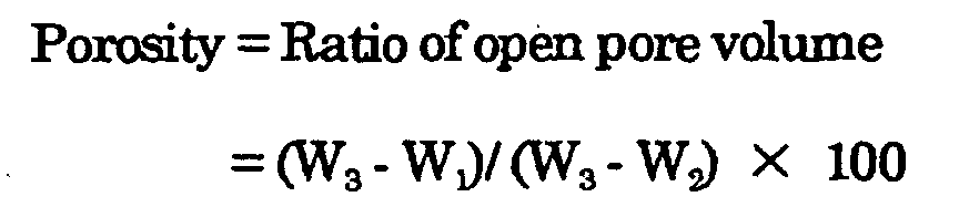 where W1 is an initial weight of a sample, W2 is a weight measured in water after
purging air from pores by decreasing the pressure or boiling in water and then
cooling, and W3 is a weight measured after being taken out of water and wiped to
remove water drops on the surface, then the porosity is given as shown above.
where W1 is an initial weight of a sample, W2 is a weight measured in water after
purging air from pores by decreasing the pressure or boiling in water and then
cooling, and W3 is a weight measured after being taken out of water and wiped to
remove water drops on the surface, then the porosity is given as shown above.
The electrical conductivity of the sintered material used in the cathode is
preferably 0.1 mS/cm or higher, and more preferably 1 mS/cm or higher This
increases the bonding strength between primary particles of the sintered material
and improves the mechanical strength of the electrode.
The sintered material of the lithium-transition metal oxide formed in the
process described above and the current collector can be integrated as follows. The
sintered material and the current collector are laminated under a pressure, and
heated at a temperature lower than the melting point of the current collector.
When aluminum is used for the current collector, heating temperature is from 50 to
600°C, preferably from 100 to 300°C, while there is no particular limitation on the
heating time as long as the duration is not less than one second. While there is no
limitation on the ambiance during heating, air atmosphere or non-oxidative
atmosphere is preferable.
The sintered material with a uniform thickness makes it possible that the
current collector is pressed to the sintered material uniformly over the entire surface e
thereof. For the purpose of forming the sintered material with a uniform thickness,
the method described previously where the coating film is formed on the organic
polymer film is preferable, but a method of polishing the surface of the sintered
material may also be employed.
As the cathode current collector in the present invention, aluminum,
titanium or stainless steel, or an alloy that includes any of these may be used, while
aluminum is preferable. This material may be in the form of either foil or mesh.
When a sintered material is used for the anode, it may be joined with the
anode current collector by, for example, a method described below. The sintered
material is pressed to the current collector and heated at a temperature lower than
the melting point of the current collector. When copper is used for the current
collector, heating temperature is from 50 to 1000°C, while there is no particular
limitation on the heating time as long as the duration is not less than one second.
The ambiance during heating is preferably air atmosphere or non-oxidative
atmosphere. Or, alternatively, a coating film including an active material may be
formed on the current collector, which is then heated to sinter.
The present invention will now be described in detail below, by way of
preferred embodiments thereof.
A battery of the first embodiment was produced by a method described
below.
60 Parts by weight (hereinafter parts by weight are abbreviated to parts) of
LiCoO2 was mixed with 3.4 parts of polyvinyl butyral as a binder, 0.85 parts of
dioctyl adipate as a plasticizer and 28 parts of a mixed solvent of toluene and 1-butyl
alcohol in a volume ratio of 4:1, and the mixture was kneaded in a ball mill for 24
hours. This coating solution was applied to a polyester film having a thickness of 50
µ m that had been treated with silicone, then the film was dried at 80°C for 20
minutes thereby to obtain a coating film having a size of 300 × 150 mm. The
coating film was removed from the polyester film and was cut into pieces having a
size of 30 × 40 mm, which were fired at 900°C in air atmosphere for 10 hours,
thereby to obtain a sintered body of LiCoO2 having a thickness of 300 µm ± 3%
and porosity of 41%. The shrinkage ratio after firing {= 1 - (Length after firing/
Length before firing) was about 7%. The electrical conductivity of the sintered
material was measured by the method described below. As a result, it was 13
mS/cm.
The electrical conductivity of the sintered material was measured by the
four-terminal method. Four leads were connected to the sintered material parallel
to each other at a predetermined space from each other, with the outermost two
leads used for supplying current and the innermost two leads used for measuring
voltage, being connected to current source and a volt meter, respectively. While
changing the current I from -1 mAto +1 mA, voltage V was measured to determine
the resistance R, and the conductivity σ was calculated by the following equation:
σ = (R × A/l)-1
where l is a distance between the two voltage measuring leads, and A is a cross
sectional area of the sintered material perpendicular to the direction of current.
With an aluminum foil having a thickness of 14 µ =m being attached to the
sintered material, the sintered material was heated to 300°C, then cooled down to
the room temperature, thereby to obtain a cathode integrated with the current
collector.
90 Parts of crystalline silicon powder of purity 99.9% having a mean particle
diameter of about 1 µ =m and 70 parts of a N-methyl-2-pyrrolidone (hereinafter
abbreviated to NMP) solution of poly (vinylidene fluoride) (14% by weight) were
mixed to prepare a uniform coating solution. This coating solution was applied to
the copper foil of the current collector and dried at 80°C for 20 minutes. The dried
film was punched through to obtain a piece having a size of 20 X=× 40 mm, that was
fired at 800°C in nitrogen atmosphere for three hours, thereby to form an anode
integrated with the current collector.
An electrolytic solution was prepared by dissolving 1 mol/L of LiPF6 in a
mixed solvent of propylene carbonate and dimethyl carbonate in a volume ratio of
1:1. The cathode and the anode described above were piled via a separator made of
a porous polyethylene film, and the stack was put into a battery housing, with the
battery housing being filled with the electrolytic solution and sealed, thereby making
the battery.
The battery made by the method described above will be referred to as
sample No. 1. After leaving the sample No. 1 to stand at the room temperature for
a full day, charge and discharge test was conducted, with the result showing the
discharge capacity of 55 mAh in the first cycle and the capacity retention ratio {=
(discharge capacity in 50th cycle/ discharge capacity in 1st cycle) × 100} of 90% in
the fiftieth cycle.
Sample No. 2 is a battery that employs a cathode made by the cathode
forming method described above, except that 3 parts of spherical polymethyl
methacrylate (PMMA) having a diameter of 5 µm was added as a pore forming
agent to the coating solution. Sample No. 2 had a porosity of 43%. The shrinkage
ratio of the sintered body after firing was about 7%, and the electrical conductivity
was 5 mS/cm. The discharge capacity in the first cycle was 60 mAh and the
capacity retention ratio in the fiftieth cycle was 90%.
Sample No. 3 is a battery that employs a sintered material having a
thickness of 300 µm ± 3% and porosity of 43% made by the cathode forming
method described above by firing at a temperature of 900°C for three hours in air
atmosphere. The shrinkage ratio of the sintered body after firing was about 2%,
and the electrical conductivity was 0.04 mS/cm. The discharge capacity in the first
cycle was 60 mAh and the capacity retention ratio in the fiftieth cycle was 10%.
Sample No.4 employed a molded material instead of a coating film in
forming the cathode. 10 Parts of polyethylene powder was added as an auxiliary
forming agent to 100 parts of LiCoO2 powder Although it was attempted to press
the mixture in a die to make a molded material having a size of 20 × 40 mm, the
powder could not be packed uniformly and the molded material could not be made.
The results obtained from the samples No. 1 to No. 3 show that a sintered
material having higher electrical conductivity has higher shrinkage ratio after firing,
indicating bonding between the primary particles that constitute the sintered
material is accelerated resulting in increased bonding force between the primary
particles. Also higher battery capacity retention ratio was achieved with a sintered
material of higher electaical conductivity. This is supposedly because the high
bonding force between the primary particles prevents the primary particles from
coming off and the electrode from disintegrating even after the electrode has
repeated expansion and shrinkage during the charge and discharge cycles.
Moreover, since the sintered material is used, filling density of active material is high
and the battery capacity per unit area is large. The result of sample No.4 shows
that it is difficult to make the cathode having a large surface area by the method of
using molded material.
Batteries according to the second embodiment were produced by the
following method.
Lithium carbonate powder and cobalt carbonate powder were mixed in a
molar ratio of Li/Co = 1/1, and the mixture was calcinated at a temperature of 800°C
for 5 hours in air atmosphere. This was ground to make calcinated powder.
Spherical PMMA particles having a mean particle diameter of 5 µ m was mixed as
a pore-forming agent by 5wt% to the calcinated powder, with the mixed powder
being pressed into a molded material which was fired at a temperature of 900°C for
10 hours in air atmosphere, thereby to obtain a pellet-shaped sintered material of 19
mm in diameter and 94 µm in thickness, having a density of 3.0 g/cm3 and porosity
of 41%. The electrical conductivity of this sintered material was 5 mS/cm.
With an aluminum foil having a thickness of 14 µ m being attached, the
cathode was heated to 300°C. After cooling down the cathode to the room
temperature, peel-off test was conducted to make sure that the aluminum foil and
the sintered material were integrated.
With 3 parts of polyvinylidene fluoride being dissolved in 70 parts of NMP,
27 parts of natural graphite having a particle diameter of about 10 µm was added
and mixed in a vibration mill to prepare a coating solution. The coating solution
thus prepared was applied to a copper foil having a thickness of 14 µm by using a
Baker's applicator thereby forming a coating film having thickness 74 µm which
was used as the anode.
The cathode integrated with a current collector, the anode and a porous
polyethylene film were stacked so that the active material surfaces of both electrodes
face each other via the porous polyethylene film, and the laminate was immersed in
an electrolytic solution that was prepared by dissolving LiPF6 in a mixed solvent of
ethylene carbonate and dimethyl carbonate in a volume ratio of 1:1, with the
concentration being adjusted to 1 mol/L, thereby making the battery of sample No.5.
Charge/discharge test was conducted under the following conditions.
Current, upper limit of voltage and charging period of constant current-constant
voltage charging were set to 4 mA, 4.1 V and 3 hours, while current and lower limit
of voltage of constant current discharging were set to 2.6 mA and 2.5 V, respectively.
Charging and discharging operations were repeated for 50 cycles, and the charge
and discharge capacities were measured.
Sample No. 6 is a battery that employs cathode made by the method
described below. lithium carbonate powder and cobalt carbonate powder were
mixed in molar proportion of Li/Co = 1/1, and the mixture was calcinated at a
temperature of 800°C for 5 hours in air atmosphere. This was ground to make
calcinated powder. 100 Parts of the calcinated powder and 8 parts of polyvinylidene
fluoride were mixed in NMP thereby to prepare a coating solution. The coating
solution was applied to an aluminum foil having a thickness of 14 µm and dried.
The dried film was punched through to obtain a pellet having a size of 19 mm in
diameter, that was pressed to an aluminum foil and heated to 500°C thereby to fire
the coating film and integrate it with the aluminum foil. The sintered material
thus obtained was 100 µm in thickness, and had a density of 3.0 g/cm3 and a
porosity of 41%.
As described above, sample No. 6 has cathode sintered and integrated with .
the current collector simultaneously. Sample No. 5, on the other hand, has cathode
formed by integrating the sintered material made by sintering at 900°C, higher than
the melting point of the aluminum foil of the current collector, and the current
collector at 300°C, lower than the melting point of the current collector.
In the charge/discharge test, the initial charging capacity of sample No. 6
was 25% that of samples No. 5. The initial charge/discharge efficiency was 98%
with sample No. 5 and 20% with sample No. 6. The discharge capacity in the 50th
cycle was 93% of the initial charge capacity with the sample No. 5, while that of the
sample No. 6 was 0% which meant that charging and discharging were impossible.
While the discharge voltage of the sample No.5 did not change after repeating 50
cycles of charge and discharge, the sample No. 6 showed a decrease in the discharge
voltage. The cathode of the sample No. 5 showed a high strength and a high
electrical conductivity, and larger battery capacity and better cycle characteristic
than the sample No. 6.
Fig. 1A-1F, Fig. 2A-2F and Fig. 3A-3F show schematic sectional views of
processes for producing the lithium secondary batteries according to this
embodiment of the present invention. The secondary battery of this embodiment
includes a stack formed of a multilayered electrode unit that includes cathodes and
anodes piled via a separator and has strip-shaped current collectors.
Fig. 1A-1F shows a battery A having a stacked electrode formed by folding a
multilayered electrode unit, Fig. 2A-2F shows a battery B having a stacked electrode
formed by winding a multilayered electrode unit, and Fig. 3A-3F shows a battery C
having a stacked electrode formed by folding the multilayered electrode unit in a
different way from the battery A.
The process of producing the battery A will be described first. Fig. 1A is a
perspective view showing the structure of a multilayered electrode unit 1. The
multilayered unit 1 comprises a cathode sheet 2 and an anode sheet 6 that oppose
each other via a separator 11. The cathode sheet 2 comprises a strip-shaped
cathode current collector 4 and a plurality of cathodes 3 made of sintered material
aligned on and joined to one side of thereof The plurality of cathodes 3 are joined
while being spaced from one another at a plurality of bending portions 5 that secure
spaces required for bending and are defined by desirable intervals on the cathode
current collector 4. The anode sheet 6 has a structure similar to that of the cathode
2, including a strip-shaped anode current collector 8 and a plurality of anodes 7
made of sintered material aligned on and joined to one side of thereof, the plurality of
anodes 7 being joined while being spaced from one another at a plurality of bending
portions 10 defined by desirable intervals on the anode current collector 8. In the
anode sheet 6, one end of the strip-shaped anode current collector 8 is stretched in
the longitudinal direction to form the anode lead 9.
When producing the battery A, the spaces of the bending portion 5 on the
cathode side and the bending portion 10 on the anode side are made substantially
equal to each other. The space of the bending portion of the electrode sheet on the
outside of bending should ideally be made larger by the amount of thickness of the
multilayered electrode unit However, since the size of the width of the electrode is
10 mm or larger in contrast to the multilayered electrode unit having thickness of
about several hundreds of micrometers, the space of the bending portion may be
made substantially the same. Therefore, when a pair of the cathode 3 and the
anode 7 disposed on the ends of the cathode sheet 2 and the anode sheet 6 are piled
to oppose each other, the multilayered electrode unit 1 can be made so that all
cathodes 3 and the anodes 7 oppose each other as shown in Fig. 1B. Fig. 1B is a
sectional view taken along lines I-T of Fig. 1A. Then the multilayered electrode unit
1 is folded by alternately folding up and folding back at the bending portions 5 and
the bending portions 10 as shown in Fig. 1C, so that the adjacent cathodes 3 oppose
each other and the adjacent anodes 7 oppose each other. Then a stacked electrode
15 is formed by completely folding the multilayered electrode unit 1(Fig. 1D). Then
the anode lead 9 that extends from the front end of the stacked electrode 15 is
welded onto an anode terminal 20 via an insulation plate 16, while the stacked
electrode 15 is housed in a can 17 so that the rear end of the stacked electrode 15 and
the cathode current collector on the outermost layer are brought into contact with
the bottom and wall surfaces of the can 17 (Fig. 1E). Then the can 17 is sealed with
a lid 18 that has a gas purging hole 21 and welded by laser. After filling the can
with a non-aqueous electrolytic solution in a non-aqueous environment, the can is
sealed to complete the battery (Fig. 1F). The anode terminal 20 is fastened onto the
lid 18 via insulating packing 19.
Fig. 2A-2F shows the process of producing the battery B. Processes other .
than those shown in Fig. 2A to 2E and the formation of the electrodes can be done
similar to the process of producing the battery A. Fig. 2A is a perspective view
showing the structure of a multi-layered unit 1'. A cathode sheet 2' and an anode
sheet 6' have a plurality of cathodes 3 and a plurality of anodes 7, both made of the
sintered material, being joined on both sides thereof. An end of the cathode sheet 2'
is located on the outermost layer after being wound, and therefore the cathode may
be joined only on one side of the cathode current collector 4. The spaces of the
bending portion 5' on the cathode side and the bending portion 10' on the anode side
are increased along the longitudinal direction of the current collector, to provide
allowance for winding. Connected to the anode sheet 6' is the strip-shaped lead 9
that protrudes sideways. The cathode sheet 2' and the anode sheet 6' are held
between two halves of one folded separator, and piled as shown in Fig. 2B, to form a
multilayered electrode unit 1'. Fig. 2B is a sectional view taken along lines II-IT of
Fig. 2A. Then the multilayered electrode unit 1' is bent at the bending portions 5', .
10' as shown in Fig. 2C, and piled so that the plurality of cathodes 3 and the plurality
of anodes 7 oppose each other via the separator 11, to form a stacked electrode 15'
(Fig. 2D). Then the strip-shaped anode lead 9 that protrudes sideways from the
anode sheet 6' is welded onto the anode terminal 20 via an insulation plate 16, while
the stacked electrode 15' is housed in the can 17 from the side opposite to the anode
lead 9 so that the cathode current collector on the outermost layer of the stacked
electrode 15' makes contact with the wall of the can 17 (Fig. 2E). The subsequent
process to complete the battery is similar to the case of the first embodiment (Fig.
2F).
Since the battery B has the plurality of cathodes and the plurality of anodes
on both sides of the cathode sheet and the anode sheet, respectively, the amount of
the active material contained can be made larger than the case of providing the
cathodes or the anodes only on one side, thus achieving a higher energy density of
the battery.
Fig. 3A-3F shows a process of producing the battery C. Fig. 3A is a
perspective view showing the structure of the cathode sheet 2, and Fig. 3B is a
sectional view taken along lines III-III' of Fig. 3A. In Fig. 3B, a pair of anodes,
which are joined on one side thereof to the anode current collector 8', are placed on
the cathode 3 at the end of the cathode sheet 2. The cathode sheet 2 includes the
strip-shaped cathode current collector 4 and a plurality of cathodes 3 formed on one
side thereof from the sintered material. The plurality of cathodes 3 are joined while
being separated by a plurality of bending portions 5 that provide spaces necessary
for bending. The cathode sheet 2 is folded on the bending portion at the end so that
the adjacent cathodes 3 hold therebetween a pair of anodes 7 that are placed on the
cathode 3 via the separator 11. Then the cathode sheet 2 and the separator 11 are
folded back at the bending portion 5 so that the adjacent cathodes 3 opposes each
other (Fig. 3B, 3C). This operation is repeated a plurality of times to fold up the
cathode sheet 2, so that the cathodes and the anodes oppose each other, thereby to
form the stacked electrode 15 (Fig. 3D). For the anodes, for example, a pair of
anodes 7 made of the sintered material joined onto a rectangular anode current
collector 8' may be used. The anode current collector 8' has the strip-shaped anode
lead 9 that protrudes at one end therof. The plurality of anode leads 9 extending
from the front end of the stacked electrode 15 is bundled into an anode-connecting
conductor 12 (Fig. 3D). Then the anode connecting conductor 12 is welded onto the
anode terminal 20 via an insulation plate 16, while the stacked electrode 15 is
housed in the can 17 so that the rear end of the stacked electrode 15 and the cathode
current collector on the outermost layer make contact with the bottom and the wall
of the can 17 (Fig. 1E). The subsequent process to complete the battery is similar to
the case of the first embodiment (Fig. 3F). An anode sheet that includes a plurality
of anodes made of sintered material may be used instead of the cathode sheet, and
sintered cathodes may be used instead of the sintered anodes. In the battery C,
since the sintered electrode sheet is folded after covering the sintered electrodes, the
electrodes can be aligned easily and displacement of the electrodes can be prevented.
In Fig. 1A-1F or Fig. 2A-2F, the anodes 7 may also be constituted from
coating film electrodes. When forming the coating film electrodes, a heat treatment
at a high temperature is not necessary unlike the case of forming the sintered
electrodes. Therefore, the electrodes can be formed more easily than the case where
the sintered material is used for the cathodes and the anodes. The coating film
electrode may be a strip-shaped current collector coated with a coating solution
containing the active material and a binder, which is then dried to integrate
therewith. For example, a coating film that includes a compound of silicon and a
carbon material or a carbon material as the anode active material may be used.
Now an example of the method of producing the battery A will be described
below.
Two sintered materials made similarly to the sample No. 1 of the first
embodiment were placed on an aluminum foil having thickness of 14 µm and
spaced from one another at a distance equal to the space of the bending portion and,
while being pressed thereon, were heated to 300°C thereby to form the cathode sheet.
After cooling down the cathode to the room temperature, peel-off test was conducted
to make sure that the aluminum foil and the sintered material were integrated
The sintered cathode having a size of 300 µ m in thickness, 2 cm in width and 4 cm
in length.
Two anode coating films were formed similarly to the anode of the first
embodiment, being spaced from one another at bending portion substantially the
same space as the bending portion of the cathode, and were fired at 800°C in
nitrogen atmosphere for 3 hours, thereby to form an anode sheet.
The cathode and the anode were piled via a separator made of .porous
polyethylene film thereby to form a multilayered electrode unit. The multilayered
electrode unit was folded at the bending portions to make the stacked electrode. By
covering the stacked electrode with an insulating film, a battery element was made.
The battery element was put into a square battery can which was filled with an
electrolytic solution prepared by adding 1 mol/L of LiPF6 to a mixed solvent of
ethylene carbonate and dimethyl carbonate in a volume ratio of 1:1. The battery
can was sealed thereby completing the battery.
With the method described above, since two cathodes are joined onto the
cathode current collector into a single body, handling is made easier than the case of
handling individual cathodes. Charge/discharge test conducted on 20 batteries
thus produced showed that all the batteries provided the charge and discharge
capacities corresponding to the active material.
Since the lithium secondary battery of the present invention employs the
cathode including the porous sintered material made from the lithium-transition
metal oxide with a porosity in a range from 15 to 60% and the electrical conductivity
of more than 0.1 mS/cm, as described above, the cathode has higher mechanical
strength. Also because the internal electrical resistance of the battery is decreased,
the battery has larger capacity and excellent cycle characteristic.
According to the method of producing the lithium secondary battery of the
present invention, since the cathode made of the material sintered at a temperature
higher than the melting point of the current collector is heated to a temperature
lower than the melting point of the current collector thereby to integrate with the
current collector, strength and electrical conductivity of the cathode can be improved
and, at the same time, contact resistance can be decreased without damaging the
current collector by thermal deformation. Thus the lithium secondary battery
having larger capacity and excellent cycle characteristic is provided.
The method of producing the lithium secondary battery of the present
invention also makes it possible to form the cathode having larger surface area and
uniform thickness and density and decrease the thickness of the lithium secondary
battery, because the coating film containing the cathode material consisting of the
lithium-transition metal oxide is sintered.
The method of producing the lithium secondary battery of the present
invention also makes it possible to improve the adhesion between the sintered
material and the current collector and decrease the electrical contact resistance,
thereby improving the cycle characteristic of the lithium secondary battery, because
the sintered material with uniform thickness is joined to the current collector by
pressing and heating.
In the lithium secondary battery of the present invention, since the
electrodes made of the sintered material are piled by accurately aligning the
cathodes and the anodes, the electrodes does not shift from the predetermined
positions. Since only one lead is required for each of the cathodes and the anodes,
electrical collection is made easier. Thus the non-aqueous secondary battery of low
cost and high reliability can be provided.
Claims (4)
- A lithium secondary battery comprising a cathode and an anode, each electrode containing an active material capable of incorporating and releasing lithium ions, wherein the cathode comprises a porous sintered material made of a lithium-transition metal oxide, and the sintered material has a porosity in a range from 15 to 60% and an electrical conductivity of more than 0.1 mS/cm.
- A process for producing a lithium secondary battery comprising a cathode and an anode, each electrode including an active material capable of incorporating and releasing lithium ions, the cathode being a sintered material formed by sintering a lithium-transition metal oxide at a temperature higher than a melting point of a current collector, said process comprising:pressing the sintered material to the current collector; andheating at a temperature lower than the melting point of the current collector, thereby integrating the sintered material and the current collector.
- The process according to claim 2, further comprising:(a) adding a binder and a solvent to a cathode material including powder of a lithium-transition metal oxide, thereby to prepare a coating solution;(b) applying the coating solution to a base material and removing the solvent to form a coating film; and(c) firing the coating film in the presence of oxygen to sinter the cathode material, thereby to form the sintered material.
- A lithium secondary battery comprising a stacked body formed of a multilayered electrode unit which includes cathodes and anodes piled via a separator and has strip-shaped current collector, wherein at least the cathodes are sintered materials which are aligned on and joined to one of the current collectors and spaced from one another at bending portions defined by desirable intervals on the current collector, and the cathodes and the anodes are disposed in the stacked body, with each anode opposed to the respective cathode.
Applications Claiming Priority (3)
| Application Number | Priority Date | Filing Date | Title |
|---|---|---|---|
| JP11165185A JP3068092B1 (en) | 1999-06-11 | 1999-06-11 | Method for producing positive electrode for non-aqueous secondary battery |
| JP16518599 | 1999-06-11 | ||
| PCT/JP2000/000642 WO2000077866A1 (en) | 1999-06-11 | 2000-02-07 | Lithium secondary cell and its producing method |
Publications (2)
| Publication Number | Publication Date |
|---|---|
| EP1113511A1 true EP1113511A1 (en) | 2001-07-04 |
| EP1113511A4 EP1113511A4 (en) | 2007-08-08 |
Family
ID=15807466
Family Applications (1)
| Application Number | Title | Priority Date | Filing Date |
|---|---|---|---|
| EP00902113A Withdrawn EP1113511A4 (en) | 1999-06-11 | 2000-02-07 | Lithium secondary cell and its producing method |
Country Status (5)
| Country | Link |
|---|---|
| US (1) | US6679926B1 (en) |
| EP (1) | EP1113511A4 (en) |
| JP (1) | JP3068092B1 (en) |
| KR (1) | KR100624741B1 (en) |
| WO (1) | WO2000077866A1 (en) |
Cited By (20)
| Publication number | Priority date | Publication date | Assignee | Title |
|---|---|---|---|---|
| WO2003049214A3 (en) * | 2001-11-29 | 2003-09-18 | 3M Innovative Properties Co | Discontinuous cathode sheet halfcell web |
| WO2005021411A3 (en) * | 2003-08-27 | 2005-05-19 | Eldor Corp Spa | Apparatus and method for folding a sheet material |
| FR2870639A1 (en) * | 2004-05-19 | 2005-11-25 | Electricite De France | CURRENT COLLECTOR TYPE SUPPORT AND ITS USE AS A BATTERY ELECTRODE |
| KR100537607B1 (en) * | 1999-08-30 | 2005-12-19 | 삼성에스디아이 주식회사 | Folding type electrode assembly and secondary battery with the same |
| WO2005008827A3 (en) * | 2003-07-21 | 2006-03-16 | Eldor Corp Spa | Electrode assembly and method of manufacturing same |
| EP1923937A1 (en) | 2006-11-20 | 2008-05-21 | Samsung SDI Co., Ltd. | An electrode for a rechargeable litium battery and a rechargeable lithium battery fabricated therefrom |
| WO2010062391A3 (en) * | 2008-11-26 | 2010-07-22 | Massachusetts Institute Of Technology | Batteries and electrodes for use thereof |
| US7988746B2 (en) | 2000-10-20 | 2011-08-02 | A123 Systems, Inc. | Battery structures, self-organizing structures and related methods |
| US8148009B2 (en) | 2000-10-20 | 2012-04-03 | Massachusetts Institute Of Technology | Reticulated and controlled porosity battery structures |
| CN101853931B (en) * | 2009-04-01 | 2012-12-19 | 中国科学院金属研究所 | Preparation method of porous conductive LiFePO4 positive plate for lithium ion battery |
| WO2013153261A1 (en) * | 2012-04-11 | 2013-10-17 | Nokia Corporation | Battery pack |
| US8709647B2 (en) | 2000-10-20 | 2014-04-29 | A123 Systems Llc | Battery structures and related methods |
| CN103959540A (en) * | 2012-11-23 | 2014-07-30 | 株式会社Lg化学 | Method for preparing electrode assembly and electrode assembly prepared using said method |
| US9065093B2 (en) | 2011-04-07 | 2015-06-23 | Massachusetts Institute Of Technology | Controlled porosity in electrodes |
| EP2843745A4 (en) * | 2012-04-27 | 2015-12-16 | Nihon Micronics Kk | SECONDARY CELL |
| CN109346778A (en) * | 2018-10-08 | 2019-02-15 | 东莞阿李自动化股份有限公司 | A method of manufacturing a laminated battery |
| US10569480B2 (en) | 2014-10-03 | 2020-02-25 | Massachusetts Institute Of Technology | Pore orientation using magnetic fields |
| US10675819B2 (en) | 2014-10-03 | 2020-06-09 | Massachusetts Institute Of Technology | Magnetic field alignment of emulsions to produce porous articles |
| EP4152434A1 (en) * | 2021-09-17 | 2023-03-22 | VARTA Microbattery GmbH | Energy storage element |
| DE102021125288A1 (en) | 2021-09-29 | 2023-03-30 | Volkswagen Aktiengesellschaft | Battery cell and method for its manufacture |
Families Citing this family (53)
| Publication number | Priority date | Publication date | Assignee | Title |
|---|---|---|---|---|
| KR100525828B1 (en) * | 2001-04-25 | 2005-11-03 | 에스케이씨 주식회사 | A button cell type lithium battery and its manufacturing method |
| KR100509437B1 (en) * | 2003-01-27 | 2005-08-26 | 주식회사 에너랜드 | Stacked type lithium secondary battery and its fabrication |
| KR100759556B1 (en) * | 2005-10-17 | 2007-09-18 | 삼성에스디아이 주식회사 | Anode active material, method of preparing the same, and anode and lithium battery containing the material |
| US8883354B2 (en) | 2006-02-15 | 2014-11-11 | Optodot Corporation | Separators for electrochemical cells |
| US7972731B2 (en) * | 2006-03-08 | 2011-07-05 | Enerl, Inc. | Electrode for cell of energy storage device and method of forming the same |
| US7483260B2 (en) * | 2006-12-22 | 2009-01-27 | Greatbatch Ltd. | Dual anode capacitor with internally connected anodes |
| US20120196189A1 (en) | 2007-06-29 | 2012-08-02 | Johnson Ip Holding, Llc | Amorphous ionically conductive metal oxides and sol gel method of preparation |
| US9034525B2 (en) * | 2008-06-27 | 2015-05-19 | Johnson Ip Holding, Llc | Ionically-conductive amorphous lithium lanthanum zirconium oxide |
| US20090092903A1 (en) * | 2007-08-29 | 2009-04-09 | Johnson Lonnie G | Low Cost Solid State Rechargeable Battery and Method of Manufacturing Same |
| TWI369019B (en) * | 2007-12-27 | 2012-07-21 | Ind Tech Res Inst | Cathodal materials for lithium cells, methods for fabricating the same, and lithium secondary cells using the same |
| JP2011520214A (en) * | 2008-03-25 | 2011-07-14 | エイ 123 システムズ,インク. | High energy high power electrodes and batteries |
| WO2009157158A1 (en) * | 2008-06-23 | 2009-12-30 | パナソニック株式会社 | Nonaqueous electrolyte secondary battery |
| US9099738B2 (en) * | 2008-11-03 | 2015-08-04 | Basvah Llc | Lithium secondary batteries with positive electrode compositions and their methods of manufacturing |
| US8163421B2 (en) * | 2009-03-09 | 2012-04-24 | Tsun-Yu Chang | High durability lithium-ion cells |
| KR101084075B1 (en) | 2009-11-03 | 2011-11-16 | 삼성에스디아이 주식회사 | Secondary Battery and Manufacturing Method Thereof |
| CN106784556A (en) | 2010-07-19 | 2017-05-31 | 奥普图多特公司 | For the barrier film of electrochemical cell |
| KR101199125B1 (en) | 2010-09-02 | 2012-11-09 | 삼성에스디아이 주식회사 | Electrode assembly including bending portions and secondary battery having the same |
| US9289611B2 (en) | 2011-11-22 | 2016-03-22 | Medtronic, Inc. | Electrochemical cell with adjacent cathodes |
| US8802283B2 (en) * | 2012-01-19 | 2014-08-12 | Samsung Sdi Co., Ltd. | Fabricating method of secondary battery |
| KR101945968B1 (en) | 2012-03-01 | 2019-02-11 | 엑셀라트론 솔리드 스테이트 엘엘씨 | High Capacity Solid State Composite Cathode, Solid State Composite Separator, Solid-State Rechargeable Lithium Battery and Methods of Making Same |
| US9793525B2 (en) | 2012-10-09 | 2017-10-17 | Johnson Battery Technologies, Inc. | Solid-state battery electrodes |
| KR101439834B1 (en) * | 2012-11-08 | 2014-09-17 | 주식회사 엘지화학 | Flexible jelly roll type secondary battery |
| JP2014102954A (en) * | 2012-11-19 | 2014-06-05 | Toyota Motor Corp | Battery and manufacturing method thereof |
| JP6201327B2 (en) * | 2013-02-05 | 2017-09-27 | セイコーエプソン株式会社 | Method for producing electrode composite for lithium battery, electrode composite for lithium battery, and lithium battery |
| JP2014154236A (en) * | 2013-02-05 | 2014-08-25 | Seiko Epson Corp | Method for manufacturing electrode composite body |
| JP2014154239A (en) * | 2013-02-05 | 2014-08-25 | Seiko Epson Corp | Method for manufacturing active material compact, active material compact, method for manufacturing lithium battery, and lithium battery |
| US9246185B2 (en) | 2013-03-14 | 2016-01-26 | Sion Power Corporation | Electrochemical cell having a folded electrode and separator, battery including the same, and method of forming same |
| KR102236436B1 (en) | 2013-04-29 | 2021-04-06 | 옵토도트 코포레이션 | Nanoporous composite separators with increased thermal conductivity |
| KR101517522B1 (en) * | 2013-07-19 | 2015-05-06 | 가천대학교 산학협력단 | Anode Substrate, all solid state battery with high capacity, and methods for manufacturing the same |
| US10535898B2 (en) * | 2014-12-17 | 2020-01-14 | Solvay Sa | Nonaqueous electrolyte compositions comprising lithium malonatoborate and fluorinated solvent |
| US10199684B2 (en) * | 2014-12-17 | 2019-02-05 | Solvay Sa | Nonaqueous electrolyte compositions comprising lithium glycolatoborate and fluorinated solvent |
| JP6986827B2 (en) * | 2015-02-12 | 2021-12-22 | 株式会社半導体エネルギー研究所 | Power storage device and electronic equipment |
| US10381623B2 (en) | 2015-07-09 | 2019-08-13 | Optodot Corporation | Nanoporous separators for batteries and related manufacturing methods |
| US20170098857A1 (en) * | 2015-04-15 | 2017-04-06 | Optodot Corporation | Coated stacks for batteries and related manufacturing methods |
| CN112993411A (en) * | 2015-04-15 | 2021-06-18 | 奥普图多特公司 | Coated stack for a battery and associated manufacturing method |
| US12040506B2 (en) | 2015-04-15 | 2024-07-16 | Lg Energy Solution, Ltd. | Nanoporous separators for batteries and related manufacturing methods |
| US10083798B2 (en) * | 2015-09-16 | 2018-09-25 | Cardiac Pacemakers, Inc. | Sintered electrodes for capacitor anodes, cathodes, anode systems, and cathode systems |
| KR102568787B1 (en) * | 2015-09-21 | 2023-08-21 | 삼성전자주식회사 | Cathode of three dimensional lithium secondary battery and method of fabricating the same |
| JP6763965B2 (en) | 2015-12-21 | 2020-09-30 | ジョンソン・アイピー・ホールディング・エルエルシー | Solid-state batteries, separators, electrodes and manufacturing methods |
| US10218044B2 (en) | 2016-01-22 | 2019-02-26 | Johnson Ip Holding, Llc | Johnson lithium oxygen electrochemical engine |
| WO2019089926A1 (en) * | 2017-11-01 | 2019-05-09 | University Of Virginia Patent Foundation | Sintered electrode cells for high energy density batteries and related methods thereof |
| KR102778726B1 (en) | 2018-03-15 | 2025-03-12 | 에스케이온 주식회사 | Electrode for Secondary Battery and the Fabrication Method Thereof |
| US20190319263A1 (en) * | 2018-04-13 | 2019-10-17 | Nanotek Instruments, Inc. | Alkali metal-selenium secondary battery containing a cathode of protected selenium |
| US11637353B2 (en) | 2018-12-27 | 2023-04-25 | Sion Power Corporation | Electrodes, heaters, sensors, and associated articles and methods |
| JP7596273B2 (en) | 2018-12-27 | 2024-12-09 | シオン・パワー・コーポレーション | Electrochemical devices and related articles, components, configurations and methods |
| US11322804B2 (en) | 2018-12-27 | 2022-05-03 | Sion Power Corporation | Isolatable electrodes and associated articles and methods |
| JP7061588B2 (en) * | 2019-04-24 | 2022-04-28 | 本田技研工業株式会社 | Manufacturing method of all-solid-state battery and all-solid-state battery |
| JP7596690B2 (en) * | 2019-12-18 | 2024-12-10 | 日本電気硝子株式会社 | All-solid-state sodium ion secondary battery and method for producing the same |
| US11411289B2 (en) * | 2020-08-19 | 2022-08-09 | Millibatt, Inc. | Three-dimensional folded battery unit and methods for manufacturing the same |
| BR112023022296A2 (en) | 2021-04-29 | 2023-12-26 | 24M Tech Inc | ELECTROCHEMICAL CELLS WITH MULTIPLE SEPARATORS, AND PRODUCTION METHODS THEREOF |
| CN119256422A (en) * | 2022-06-17 | 2025-01-03 | 元平台技术有限公司 | Devices, systems and methods for achieving flexibility and durability of batteries |
| TW202443944A (en) | 2022-12-16 | 2024-11-01 | 美商24M科技公司 | Systems and methods for minimizing and preventing dendrite formation in electrochemical cells |
| US12431545B1 (en) | 2024-03-26 | 2025-09-30 | 24M Technologies, Inc. | Systems and methods for minimizing and preventing dendrite formation in electrochemical cells |
Family Cites Families (17)
| Publication number | Priority date | Publication date | Assignee | Title |
|---|---|---|---|---|
| CA2096386A1 (en) * | 1992-05-18 | 1993-11-19 | Masahiro Kamauchi | Lithium secondary battery |
| JP3427570B2 (en) * | 1994-10-26 | 2003-07-22 | ソニー株式会社 | Non-aqueous electrolyte secondary battery |
| US6001139A (en) * | 1995-03-06 | 1999-12-14 | Fuji Photo Film Co., Ltd. | Nonaqueous secondary battery having multiple-layered negative electrode |
| JPH0945334A (en) | 1995-07-26 | 1997-02-14 | Katayama Tokushu Kogyo Kk | Base material for lithium secondary battery plate, electrode plate using this base material and secondary battery using this electrode plate |
| US5773168A (en) * | 1995-08-23 | 1998-06-30 | Kabushiki Kaisha Toshiba | Nonaqueous electrolyte secondary battery and method for manufacturing the same |
| US5989747A (en) * | 1996-07-10 | 1999-11-23 | Fuji Photo Film Co., Ltd. | Cell electrode with thick tip portions |
| JPH10144303A (en) * | 1996-11-13 | 1998-05-29 | Fuji Photo Film Co Ltd | Manufacture of electrode sheet and its device |
| US6287728B1 (en) * | 1996-12-24 | 2001-09-11 | Kao Corporation | Nonaqueous electrolyte secondary battery |
| JPH10302828A (en) | 1997-04-28 | 1998-11-13 | Mitsubishi Cable Ind Ltd | Angular battery and manufacture thereof |
| JPH11154534A (en) | 1997-11-19 | 1999-06-08 | Asahi Chem Ind Co Ltd | Lithium ion secondary battery element |
| WO1999059218A1 (en) * | 1998-05-12 | 1999-11-18 | Ecole Polytechnique Federale De Lausanne (Epfl) Sri | Primary or secondary electrochemical generator |
| JP2000011994A (en) * | 1998-06-19 | 2000-01-14 | Kao Corp | Positive electrode for non-aqueous secondary batteries |
| JP2000011993A (en) * | 1998-06-19 | 2000-01-14 | Kao Corp | Positive electrode for non-aqueous secondary batteries |
| JP2000012024A (en) | 1998-06-24 | 2000-01-14 | Kao Corp | Method for producing positive electrode for non-aqueous secondary battery |
| JP2000082464A (en) * | 1998-09-02 | 2000-03-21 | Kao Corp | Non-aqueous secondary battery |
| US6287721B1 (en) * | 1998-09-24 | 2001-09-11 | Thomas & Betts International, Inc. | Process for manufacturing electrochemical cells |
| US6494021B1 (en) * | 1999-02-18 | 2002-12-17 | Johnson & Johnson Vision Care, Inc. | Contact lens transfer and material removal system |
-
1999
- 1999-06-11 JP JP11165185A patent/JP3068092B1/en not_active Expired - Fee Related
-
2000
- 2000-02-07 KR KR1020017001789A patent/KR100624741B1/en not_active Expired - Fee Related
- 2000-02-07 US US09/762,701 patent/US6679926B1/en not_active Expired - Fee Related
- 2000-02-07 WO PCT/JP2000/000642 patent/WO2000077866A1/en not_active Ceased
- 2000-02-07 EP EP00902113A patent/EP1113511A4/en not_active Withdrawn
Cited By (36)
| Publication number | Priority date | Publication date | Assignee | Title |
|---|---|---|---|---|
| KR100537607B1 (en) * | 1999-08-30 | 2005-12-19 | 삼성에스디아이 주식회사 | Folding type electrode assembly and secondary battery with the same |
| US8586238B2 (en) | 2000-10-20 | 2013-11-19 | Massachusetts Institute Of Technology | Battery structures, self-organizing structures, and related methods |
| US8148009B2 (en) | 2000-10-20 | 2012-04-03 | Massachusetts Institute Of Technology | Reticulated and controlled porosity battery structures |
| US8709647B2 (en) | 2000-10-20 | 2014-04-29 | A123 Systems Llc | Battery structures and related methods |
| US8580430B2 (en) | 2000-10-20 | 2013-11-12 | Massachusetts Institute Of Technology | Battery structures, self-organizing structures, and related methods |
| US8277975B2 (en) | 2000-10-20 | 2012-10-02 | Massachusetts Intitute Of Technology | Reticulated and controlled porosity battery structures |
| US8241789B2 (en) | 2000-10-20 | 2012-08-14 | Massachusetts Institute Of Technology | Battery structures, self-organizing structures and related methods |
| US8206468B2 (en) | 2000-10-20 | 2012-06-26 | Massachusetts Institute Of Technology | Battery structures, self-organizing structures and related methods |
| US8168326B2 (en) | 2000-10-20 | 2012-05-01 | A123 Systems, Inc. | Battery structures, self-organizing structures and related methods |
| US7988746B2 (en) | 2000-10-20 | 2011-08-02 | A123 Systems, Inc. | Battery structures, self-organizing structures and related methods |
| WO2003049214A3 (en) * | 2001-11-29 | 2003-09-18 | 3M Innovative Properties Co | Discontinuous cathode sheet halfcell web |
| US6830846B2 (en) | 2001-11-29 | 2004-12-14 | 3M Innovative Properties Company | Discontinuous cathode sheet halfcell web |
| WO2005008827A3 (en) * | 2003-07-21 | 2006-03-16 | Eldor Corp Spa | Electrode assembly and method of manufacturing same |
| WO2005021411A3 (en) * | 2003-08-27 | 2005-05-19 | Eldor Corp Spa | Apparatus and method for folding a sheet material |
| WO2005114766A3 (en) * | 2004-05-19 | 2006-05-04 | Electricite De France | Component comprising an electron collector and an active material, and the use thereof as a battery electrode |
| FR2870639A1 (en) * | 2004-05-19 | 2005-11-25 | Electricite De France | CURRENT COLLECTOR TYPE SUPPORT AND ITS USE AS A BATTERY ELECTRODE |
| US8877373B2 (en) | 2006-11-20 | 2014-11-04 | Samsung Sdi Co., Ltd. | Electrode for a rechargeable lithium battery, and a rechargeable lithium battery fabricated therefrom |
| EP1923937A1 (en) | 2006-11-20 | 2008-05-21 | Samsung SDI Co., Ltd. | An electrode for a rechargeable litium battery and a rechargeable lithium battery fabricated therefrom |
| US8999571B2 (en) | 2007-05-25 | 2015-04-07 | Massachusetts Institute Of Technology | Batteries and electrodes for use thereof |
| WO2010062391A3 (en) * | 2008-11-26 | 2010-07-22 | Massachusetts Institute Of Technology | Batteries and electrodes for use thereof |
| CN101853931B (en) * | 2009-04-01 | 2012-12-19 | 中国科学院金属研究所 | Preparation method of porous conductive LiFePO4 positive plate for lithium ion battery |
| US9065093B2 (en) | 2011-04-07 | 2015-06-23 | Massachusetts Institute Of Technology | Controlled porosity in electrodes |
| US10164242B2 (en) | 2011-04-07 | 2018-12-25 | Massachusetts Institute Of Technology | Controlled porosity in electrodes |
| WO2013153261A1 (en) * | 2012-04-11 | 2013-10-17 | Nokia Corporation | Battery pack |
| US9401502B2 (en) | 2012-04-11 | 2016-07-26 | Nokia Technologies Oy | Battery pack |
| US9972862B2 (en) | 2012-04-27 | 2018-05-15 | Kabushiki Kaisha Nihon Micronics | Secondary battery |
| EP2843745A4 (en) * | 2012-04-27 | 2015-12-16 | Nihon Micronics Kk | SECONDARY CELL |
| CN103959540B (en) * | 2012-11-23 | 2016-06-08 | 株式会社Lg化学 | Method for preparing electrode assembly and electrode assembly prepared using said method |
| CN103959540A (en) * | 2012-11-23 | 2014-07-30 | 株式会社Lg化学 | Method for preparing electrode assembly and electrode assembly prepared using said method |
| US10569480B2 (en) | 2014-10-03 | 2020-02-25 | Massachusetts Institute Of Technology | Pore orientation using magnetic fields |
| US10675819B2 (en) | 2014-10-03 | 2020-06-09 | Massachusetts Institute Of Technology | Magnetic field alignment of emulsions to produce porous articles |
| CN109346778A (en) * | 2018-10-08 | 2019-02-15 | 东莞阿李自动化股份有限公司 | A method of manufacturing a laminated battery |
| EP4152434A1 (en) * | 2021-09-17 | 2023-03-22 | VARTA Microbattery GmbH | Energy storage element |
| WO2023041290A1 (en) * | 2021-09-17 | 2023-03-23 | Varta Microbattery Gmbh | Energy storage element |
| DE102021125288A1 (en) | 2021-09-29 | 2023-03-30 | Volkswagen Aktiengesellschaft | Battery cell and method for its manufacture |
| CN115882042A (en) * | 2021-09-29 | 2023-03-31 | 大众汽车股份公司 | Battery cell and method for producing same |
Also Published As
| Publication number | Publication date |
|---|---|
| US6679926B1 (en) | 2004-01-20 |
| KR20010082127A (en) | 2001-08-29 |
| WO2000077866A1 (en) | 2000-12-21 |
| JP3068092B1 (en) | 2000-07-24 |
| EP1113511A4 (en) | 2007-08-08 |
| JP2000353512A (en) | 2000-12-19 |
| KR100624741B1 (en) | 2006-09-19 |
Similar Documents
| Publication | Publication Date | Title |
|---|---|---|
| US6679926B1 (en) | Lithium secondary cell and its producing method | |
| JP4038699B2 (en) | Lithium ion battery | |
| EP2058892B1 (en) | Total solid rechargeable battery | |
| EP1777761B1 (en) | Lithium Rechargeable Battery | |
| JP2020024934A (en) | Lithium battery using nanoporous separator layer | |
| CN104541401A (en) | Manufacturing of Solid State Battery Packs | |
| EP1120849A2 (en) | Gel electrolyte battery | |
| US11967678B2 (en) | All solid-state lithium-ion battery incorporating electrolyte-infiltrated composite electrodes | |
| KR100624971B1 (en) | Electrode plate for secondary battery and manufacturing method thereof | |
| US6371997B1 (en) | Method for manufacturing lithium polymer secondary battery and lithium polymer secondary battery made by the method | |
| JP2001160393A (en) | Non-aqueous secondary battery | |
| KR20230069974A (en) | Lithium-ion cells with high specific energy density | |
| JP3243239B2 (en) | Method for producing positive electrode for non-aqueous secondary battery | |
| JP2001520441A (en) | Lithium-ion polymer battery separator | |
| US6737196B2 (en) | Method of making a lithium polymer battery and battery made by the method | |
| WO2023162318A1 (en) | All-solid-state battery | |
| KR100509435B1 (en) | Lithium secondary battery and its fabrication | |
| US20240413299A1 (en) | Solid state battery containing continuous glass-ceramic electrolyte separator and perforated sintered solid-state battery cathode | |
| JPH09161806A (en) | Secondary battery electrode or secondary battery | |
| KR100439351B1 (en) | Rechargeable Lithium Polymer Battery and Method for Making the Same | |
| JP2000212322A (en) | Polyolefin microporous membrane | |
| KR20140072794A (en) | Non-aqueous electrolyte rechargeable battery pack | |
| KR100625958B1 (en) | Lithium secondary battery and manufacturiing method therefor | |
| JP2002100345A (en) | Method for producing positive electrode for non-aqueous secondary battery | |
| KR100470594B1 (en) | Rechargeable Lithium Polymer Battery and Method for Making the Same |
Legal Events
| Date | Code | Title | Description |
|---|---|---|---|
| PUAI | Public reference made under article 153(3) epc to a published international application that has entered the european phase |
Free format text: ORIGINAL CODE: 0009012 |
|
| 17P | Request for examination filed |
Effective date: 20010417 |
|
| AK | Designated contracting states |
Kind code of ref document: A1 Designated state(s): AT BE CH CY DE DK ES FI FR GB GR IE IT LI LU MC NL PT SE |
|
| RBV | Designated contracting states (corrected) |
Designated state(s): DE FR GB |
|
| A4 | Supplementary search report drawn up and despatched |
Effective date: 20070711 |
|
| 17Q | First examination report despatched |
Effective date: 20080205 |
|
| STAA | Information on the status of an ep patent application or granted ep patent |
Free format text: STATUS: THE APPLICATION IS DEEMED TO BE WITHDRAWN |
|
| 18D | Application deemed to be withdrawn |
Effective date: 20140902 |