US7972731B2 - Electrode for cell of energy storage device and method of forming the same - Google Patents
Electrode for cell of energy storage device and method of forming the same Download PDFInfo
- Publication number
- US7972731B2 US7972731B2 US11/561,077 US56107706A US7972731B2 US 7972731 B2 US7972731 B2 US 7972731B2 US 56107706 A US56107706 A US 56107706A US 7972731 B2 US7972731 B2 US 7972731B2
- Authority
- US
- United States
- Prior art keywords
- current collector
- particles
- metal current
- cell
- metal
- Prior art date
- Legal status (The legal status is an assumption and is not a legal conclusion. Google has not performed a legal analysis and makes no representation as to the accuracy of the status listed.)
- Expired - Fee Related, expires
Links
Images


Classifications
-
- C—CHEMISTRY; METALLURGY
- C23—COATING METALLIC MATERIAL; COATING MATERIAL WITH METALLIC MATERIAL; CHEMICAL SURFACE TREATMENT; DIFFUSION TREATMENT OF METALLIC MATERIAL; COATING BY VACUUM EVAPORATION, BY SPUTTERING, BY ION IMPLANTATION OR BY CHEMICAL VAPOUR DEPOSITION, IN GENERAL; INHIBITING CORROSION OF METALLIC MATERIAL OR INCRUSTATION IN GENERAL
- C23C—COATING METALLIC MATERIAL; COATING MATERIAL WITH METALLIC MATERIAL; SURFACE TREATMENT OF METALLIC MATERIAL BY DIFFUSION INTO THE SURFACE, BY CHEMICAL CONVERSION OR SUBSTITUTION; COATING BY VACUUM EVAPORATION, BY SPUTTERING, BY ION IMPLANTATION OR BY CHEMICAL VAPOUR DEPOSITION, IN GENERAL
- C23C24/00—Coating starting from inorganic powder
- C23C24/02—Coating starting from inorganic powder by application of pressure only
- C23C24/04—Impact or kinetic deposition of particles
-
- H—ELECTRICITY
- H01—ELECTRIC ELEMENTS
- H01G—CAPACITORS; CAPACITORS, RECTIFIERS, DETECTORS, SWITCHING DEVICES OR LIGHT-SENSITIVE DEVICES, OF THE ELECTROLYTIC TYPE
- H01G11/00—Hybrid capacitors, i.e. capacitors having different positive and negative electrodes; Electric double-layer [EDL] capacitors; Processes for the manufacture thereof or of parts thereof
- H01G11/22—Electrodes
- H01G11/26—Electrodes characterised by their structure, e.g. multi-layered, porosity or surface features
- H01G11/28—Electrodes characterised by their structure, e.g. multi-layered, porosity or surface features arranged or disposed on a current collector; Layers or phases between electrodes and current collectors, e.g. adhesives
-
- H—ELECTRICITY
- H01—ELECTRIC ELEMENTS
- H01G—CAPACITORS; CAPACITORS, RECTIFIERS, DETECTORS, SWITCHING DEVICES OR LIGHT-SENSITIVE DEVICES, OF THE ELECTROLYTIC TYPE
- H01G11/00—Hybrid capacitors, i.e. capacitors having different positive and negative electrodes; Electric double-layer [EDL] capacitors; Processes for the manufacture thereof or of parts thereof
- H01G11/22—Electrodes
- H01G11/30—Electrodes characterised by their material
- H01G11/32—Carbon-based
- H01G11/42—Powders or particles, e.g. composition thereof
-
- H—ELECTRICITY
- H01—ELECTRIC ELEMENTS
- H01G—CAPACITORS; CAPACITORS, RECTIFIERS, DETECTORS, SWITCHING DEVICES OR LIGHT-SENSITIVE DEVICES, OF THE ELECTROLYTIC TYPE
- H01G11/00—Hybrid capacitors, i.e. capacitors having different positive and negative electrodes; Electric double-layer [EDL] capacitors; Processes for the manufacture thereof or of parts thereof
- H01G11/22—Electrodes
- H01G11/30—Electrodes characterised by their material
- H01G11/50—Electrodes characterised by their material specially adapted for lithium-ion capacitors, e.g. for lithium-doping or for intercalation
-
- H—ELECTRICITY
- H01—ELECTRIC ELEMENTS
- H01G—CAPACITORS; CAPACITORS, RECTIFIERS, DETECTORS, SWITCHING DEVICES OR LIGHT-SENSITIVE DEVICES, OF THE ELECTROLYTIC TYPE
- H01G11/00—Hybrid capacitors, i.e. capacitors having different positive and negative electrodes; Electric double-layer [EDL] capacitors; Processes for the manufacture thereof or of parts thereof
- H01G11/66—Current collectors
- H01G11/70—Current collectors characterised by their structure
-
- H—ELECTRICITY
- H01—ELECTRIC ELEMENTS
- H01G—CAPACITORS; CAPACITORS, RECTIFIERS, DETECTORS, SWITCHING DEVICES OR LIGHT-SENSITIVE DEVICES, OF THE ELECTROLYTIC TYPE
- H01G11/00—Hybrid capacitors, i.e. capacitors having different positive and negative electrodes; Electric double-layer [EDL] capacitors; Processes for the manufacture thereof or of parts thereof
- H01G11/84—Processes for the manufacture of hybrid or EDL capacitors, or components thereof
- H01G11/86—Processes for the manufacture of hybrid or EDL capacitors, or components thereof specially adapted for electrodes
-
- H—ELECTRICITY
- H01—ELECTRIC ELEMENTS
- H01M—PROCESSES OR MEANS, e.g. BATTERIES, FOR THE DIRECT CONVERSION OF CHEMICAL ENERGY INTO ELECTRICAL ENERGY
- H01M10/00—Secondary cells; Manufacture thereof
- H01M10/05—Accumulators with non-aqueous electrolyte
-
- H—ELECTRICITY
- H01—ELECTRIC ELEMENTS
- H01M—PROCESSES OR MEANS, e.g. BATTERIES, FOR THE DIRECT CONVERSION OF CHEMICAL ENERGY INTO ELECTRICAL ENERGY
- H01M4/00—Electrodes
- H01M4/02—Electrodes composed of, or comprising, active material
- H01M4/04—Processes of manufacture in general
-
- H—ELECTRICITY
- H01—ELECTRIC ELEMENTS
- H01M—PROCESSES OR MEANS, e.g. BATTERIES, FOR THE DIRECT CONVERSION OF CHEMICAL ENERGY INTO ELECTRICAL ENERGY
- H01M4/00—Electrodes
- H01M4/02—Electrodes composed of, or comprising, active material
- H01M4/04—Processes of manufacture in general
- H01M4/0402—Methods of deposition of the material
- H01M4/0404—Methods of deposition of the material by coating on electrode collectors
-
- H—ELECTRICITY
- H01—ELECTRIC ELEMENTS
- H01M—PROCESSES OR MEANS, e.g. BATTERIES, FOR THE DIRECT CONVERSION OF CHEMICAL ENERGY INTO ELECTRICAL ENERGY
- H01M4/00—Electrodes
- H01M4/02—Electrodes composed of, or comprising, active material
- H01M4/04—Processes of manufacture in general
- H01M4/0402—Methods of deposition of the material
- H01M4/0419—Methods of deposition of the material involving spraying
-
- H—ELECTRICITY
- H01—ELECTRIC ELEMENTS
- H01M—PROCESSES OR MEANS, e.g. BATTERIES, FOR THE DIRECT CONVERSION OF CHEMICAL ENERGY INTO ELECTRICAL ENERGY
- H01M4/00—Electrodes
- H01M4/02—Electrodes composed of, or comprising, active material
- H01M4/64—Carriers or collectors
- H01M4/66—Selection of materials
- H01M4/661—Metal or alloys, e.g. alloy coatings
-
- H—ELECTRICITY
- H01—ELECTRIC ELEMENTS
- H01M—PROCESSES OR MEANS, e.g. BATTERIES, FOR THE DIRECT CONVERSION OF CHEMICAL ENERGY INTO ELECTRICAL ENERGY
- H01M4/00—Electrodes
- H01M4/02—Electrodes composed of, or comprising, active material
- H01M4/64—Carriers or collectors
- H01M4/70—Carriers or collectors characterised by shape or form
- H01M4/75—Wires, rods or strips
-
- H—ELECTRICITY
- H01—ELECTRIC ELEMENTS
- H01M—PROCESSES OR MEANS, e.g. BATTERIES, FOR THE DIRECT CONVERSION OF CHEMICAL ENERGY INTO ELECTRICAL ENERGY
- H01M4/00—Electrodes
- H01M4/86—Inert electrodes with catalytic activity, e.g. for fuel cells
- H01M4/8647—Inert electrodes with catalytic activity, e.g. for fuel cells consisting of more than one material, e.g. consisting of composites
- H01M4/8652—Inert electrodes with catalytic activity, e.g. for fuel cells consisting of more than one material, e.g. consisting of composites as mixture
-
- H—ELECTRICITY
- H01—ELECTRIC ELEMENTS
- H01M—PROCESSES OR MEANS, e.g. BATTERIES, FOR THE DIRECT CONVERSION OF CHEMICAL ENERGY INTO ELECTRICAL ENERGY
- H01M4/00—Electrodes
- H01M4/86—Inert electrodes with catalytic activity, e.g. for fuel cells
- H01M4/88—Processes of manufacture
- H01M4/8825—Methods for deposition of the catalytic active composition
- H01M4/8828—Coating with slurry or ink
-
- H—ELECTRICITY
- H01—ELECTRIC ELEMENTS
- H01M—PROCESSES OR MEANS, e.g. BATTERIES, FOR THE DIRECT CONVERSION OF CHEMICAL ENERGY INTO ELECTRICAL ENERGY
- H01M4/00—Electrodes
- H01M4/86—Inert electrodes with catalytic activity, e.g. for fuel cells
- H01M4/94—Non-porous diffusion electrodes, e.g. palladium membranes, ion exchange membranes
-
- H—ELECTRICITY
- H01—ELECTRIC ELEMENTS
- H01M—PROCESSES OR MEANS, e.g. BATTERIES, FOR THE DIRECT CONVERSION OF CHEMICAL ENERGY INTO ELECTRICAL ENERGY
- H01M10/00—Secondary cells; Manufacture thereof
- H01M10/05—Accumulators with non-aqueous electrolyte
- H01M10/052—Li-accumulators
-
- H—ELECTRICITY
- H01—ELECTRIC ELEMENTS
- H01M—PROCESSES OR MEANS, e.g. BATTERIES, FOR THE DIRECT CONVERSION OF CHEMICAL ENERGY INTO ELECTRICAL ENERGY
- H01M4/00—Electrodes
- H01M4/02—Electrodes composed of, or comprising, active material
- H01M2004/021—Physical characteristics, e.g. porosity, surface area
-
- H—ELECTRICITY
- H01—ELECTRIC ELEMENTS
- H01M—PROCESSES OR MEANS, e.g. BATTERIES, FOR THE DIRECT CONVERSION OF CHEMICAL ENERGY INTO ELECTRICAL ENERGY
- H01M4/00—Electrodes
- H01M4/02—Electrodes composed of, or comprising, active material
- H01M2004/026—Electrodes composed of, or comprising, active material characterised by the polarity
- H01M2004/027—Negative electrodes
-
- H—ELECTRICITY
- H01—ELECTRIC ELEMENTS
- H01M—PROCESSES OR MEANS, e.g. BATTERIES, FOR THE DIRECT CONVERSION OF CHEMICAL ENERGY INTO ELECTRICAL ENERGY
- H01M4/00—Electrodes
- H01M4/02—Electrodes composed of, or comprising, active material
-
- H—ELECTRICITY
- H01—ELECTRIC ELEMENTS
- H01M—PROCESSES OR MEANS, e.g. BATTERIES, FOR THE DIRECT CONVERSION OF CHEMICAL ENERGY INTO ELECTRICAL ENERGY
- H01M4/00—Electrodes
- H01M4/02—Electrodes composed of, or comprising, active material
- H01M4/13—Electrodes for accumulators with non-aqueous electrolyte, e.g. for lithium-accumulators; Processes of manufacture thereof
- H01M4/139—Processes of manufacture
-
- Y—GENERAL TAGGING OF NEW TECHNOLOGICAL DEVELOPMENTS; GENERAL TAGGING OF CROSS-SECTIONAL TECHNOLOGIES SPANNING OVER SEVERAL SECTIONS OF THE IPC; TECHNICAL SUBJECTS COVERED BY FORMER USPC CROSS-REFERENCE ART COLLECTIONS [XRACs] AND DIGESTS
- Y02—TECHNOLOGIES OR APPLICATIONS FOR MITIGATION OR ADAPTATION AGAINST CLIMATE CHANGE
- Y02E—REDUCTION OF GREENHOUSE GAS [GHG] EMISSIONS, RELATED TO ENERGY GENERATION, TRANSMISSION OR DISTRIBUTION
- Y02E60/00—Enabling technologies; Technologies with a potential or indirect contribution to GHG emissions mitigation
- Y02E60/10—Energy storage using batteries
-
- Y—GENERAL TAGGING OF NEW TECHNOLOGICAL DEVELOPMENTS; GENERAL TAGGING OF CROSS-SECTIONAL TECHNOLOGIES SPANNING OVER SEVERAL SECTIONS OF THE IPC; TECHNICAL SUBJECTS COVERED BY FORMER USPC CROSS-REFERENCE ART COLLECTIONS [XRACs] AND DIGESTS
- Y02—TECHNOLOGIES OR APPLICATIONS FOR MITIGATION OR ADAPTATION AGAINST CLIMATE CHANGE
- Y02E—REDUCTION OF GREENHOUSE GAS [GHG] EMISSIONS, RELATED TO ENERGY GENERATION, TRANSMISSION OR DISTRIBUTION
- Y02E60/00—Enabling technologies; Technologies with a potential or indirect contribution to GHG emissions mitigation
- Y02E60/13—Energy storage using capacitors
-
- Y—GENERAL TAGGING OF NEW TECHNOLOGICAL DEVELOPMENTS; GENERAL TAGGING OF CROSS-SECTIONAL TECHNOLOGIES SPANNING OVER SEVERAL SECTIONS OF THE IPC; TECHNICAL SUBJECTS COVERED BY FORMER USPC CROSS-REFERENCE ART COLLECTIONS [XRACs] AND DIGESTS
- Y02—TECHNOLOGIES OR APPLICATIONS FOR MITIGATION OR ADAPTATION AGAINST CLIMATE CHANGE
- Y02E—REDUCTION OF GREENHOUSE GAS [GHG] EMISSIONS, RELATED TO ENERGY GENERATION, TRANSMISSION OR DISTRIBUTION
- Y02E60/00—Enabling technologies; Technologies with a potential or indirect contribution to GHG emissions mitigation
- Y02E60/30—Hydrogen technology
- Y02E60/50—Fuel cells
-
- Y—GENERAL TAGGING OF NEW TECHNOLOGICAL DEVELOPMENTS; GENERAL TAGGING OF CROSS-SECTIONAL TECHNOLOGIES SPANNING OVER SEVERAL SECTIONS OF THE IPC; TECHNICAL SUBJECTS COVERED BY FORMER USPC CROSS-REFERENCE ART COLLECTIONS [XRACs] AND DIGESTS
- Y02—TECHNOLOGIES OR APPLICATIONS FOR MITIGATION OR ADAPTATION AGAINST CLIMATE CHANGE
- Y02P—CLIMATE CHANGE MITIGATION TECHNOLOGIES IN THE PRODUCTION OR PROCESSING OF GOODS
- Y02P70/00—Climate change mitigation technologies in the production process for final industrial or consumer products
- Y02P70/50—Manufacturing or production processes characterised by the final manufactured product
-
- Y—GENERAL TAGGING OF NEW TECHNOLOGICAL DEVELOPMENTS; GENERAL TAGGING OF CROSS-SECTIONAL TECHNOLOGIES SPANNING OVER SEVERAL SECTIONS OF THE IPC; TECHNICAL SUBJECTS COVERED BY FORMER USPC CROSS-REFERENCE ART COLLECTIONS [XRACs] AND DIGESTS
- Y02—TECHNOLOGIES OR APPLICATIONS FOR MITIGATION OR ADAPTATION AGAINST CLIMATE CHANGE
- Y02T—CLIMATE CHANGE MITIGATION TECHNOLOGIES RELATED TO TRANSPORTATION
- Y02T10/00—Road transport of goods or passengers
- Y02T10/60—Other road transportation technologies with climate change mitigation effect
- Y02T10/70—Energy storage systems for electromobility, e.g. batteries
-
- Y—GENERAL TAGGING OF NEW TECHNOLOGICAL DEVELOPMENTS; GENERAL TAGGING OF CROSS-SECTIONAL TECHNOLOGIES SPANNING OVER SEVERAL SECTIONS OF THE IPC; TECHNICAL SUBJECTS COVERED BY FORMER USPC CROSS-REFERENCE ART COLLECTIONS [XRACs] AND DIGESTS
- Y10—TECHNICAL SUBJECTS COVERED BY FORMER USPC
- Y10T—TECHNICAL SUBJECTS COVERED BY FORMER US CLASSIFICATION
- Y10T29/00—Metal working
- Y10T29/10—Battery-grid making
-
- Y—GENERAL TAGGING OF NEW TECHNOLOGICAL DEVELOPMENTS; GENERAL TAGGING OF CROSS-SECTIONAL TECHNOLOGIES SPANNING OVER SEVERAL SECTIONS OF THE IPC; TECHNICAL SUBJECTS COVERED BY FORMER USPC CROSS-REFERENCE ART COLLECTIONS [XRACs] AND DIGESTS
- Y10—TECHNICAL SUBJECTS COVERED BY FORMER USPC
- Y10T—TECHNICAL SUBJECTS COVERED BY FORMER US CLASSIFICATION
- Y10T29/00—Metal working
- Y10T29/49—Method of mechanical manufacture
- Y10T29/49002—Electrical device making
- Y10T29/49108—Electric battery cell making
Definitions
- the subject invention relates to an electrode for a cell of an electrochemical device having improved cell charged capacity, recycling stability, energy and power, method for manufacturing the same.
- nanotechnology generally refers to objects, systems, mechanisms and assemblies smaller than 100 nanometers and larger than 1 nm.
- nanotechnology has been used to make products, that is, raw materials are processed and manipulated until the desired product is achieved.
- nanotechnology mimics nature by building a product from the ground up using a basic building block—the atom.
- nanotechnology atoms are arranged to create the material needed to create other products.
- nanotechnology allows for making materials stronger and lighter such as carbon nano-tube composite fibers.
- One of the areas of continuous development and research is an area of energy conversion devices, such as for example secondary batteries capable of charging electricity after discharge and having at least one electrochemical cell.
- the cell includes a pair of electrodes and an electrolyte disposed between the electrodes.
- One of the electrodes is called a cathode wherein an active material is reduced during discharge.
- the other electrode is called an anode wherein another active material is oxidized during discharge.
- Secondary batteries refer to batteries capable of charging electricity after discharge. Recently, intensive research has been conducted on lithium secondary batteries because of their high voltage and high energy density.
- the typical lithium battery having an anode containing an active material for releasing lithium ions during discharge.
- the active material may be metallic lithium and an intercalated material being capable of incorporating lithium between layers.
- the active material is deposited or coated upon a metal current collector formed from a metal tape to increase electro-conductive characteristics of at least one of the electrodes.
- PVD physical vapor deposition
- filament evaporation evaporation
- sputtering deposition evaporation deposition
- CVD chemical vapor deposition
- Sputtering techniques such as RF or DC sputtering, as well as laser evaporation, plasma arc evaporation, electro-spark deposition (ESD), and the like are also known to have low deposition rates.
- ESD electro-spark deposition
- all of the aforementioned methods are performed by and require expensive vacuum equipment and do not provide strong adhesion of the coating to the substrate, which is detrimental in various applications, particularly in manufacturing electrodes for energy conversion devices, such as batteries.
- Another disadvantage of the methods mentioned above that negatively impacts both the life span of the battery and the manufacturing costs associates therewith is the structure of the battery wherein the active layer is formed on the metal current collector and additional binders used as adhesion between the active layer and the metal current collector thereby increasing both the weight and size of the battery, which, as mentioned above, negatively impacts both specific characteristics of the battery and the manufacturing costs associates therewith.
- a metal current collector of the present invention is formed from a metallic tape used to form a first electrode such as an anode and a second electrode such as cathode combined into a cell for producing electric power without limiting the scope of the present invention.
- the metal current collector of the first electrode and the second electrode has opposed sides defining an initial thickness.
- An active core is formed inside the metal current collector.
- the active core is formed from first particles being integral with and extending from the metal current collector of at least one of the first and second electrodes and second particles formed from material other that the first particles of the metal current collector.
- the first and second particles connect with one another to form a porous grid of a three dimensional configuration of the active core disposed inside the metal current collector thereby resulting in the metal current collector being integral with the active core and presenting a second thickness. Based on application requirements, the second thickness may be substantially the same or smaller than the first thickness.
- the active core is mixed with and covered by an electrolyte.
- a layer of isolating bar is continuously disposed about one of the opposed sides of the metal current collector of at least one of the first and second electrodes.
- An anode layer is formed from lithium, carbon or other covering the active core to extend co-planarly with the layer of isolating bar.
- An anode current collector is formed from copper, nickel or other metal to extend over the anode layer and the layer of isolating bar.
- An isolating layer extends over the anode current collector sandwiched between the anode layer and the isolating layer.
- An advantage of the present invention is to provide a unique metal current collector of an electrode with integrated active core having a porous structure received by effective deposition of an active material into the metal current collector substrate in a binder free fashion while maintaining outstanding adhesion.
- Another advantage of the present invention is to provide a current collector wherein an active layer is formed inside the current collector thereby increasing the specific characteristics of the cell.
- Still another advantage of the present invention is to provide a unique method for fabricating the electrodes wherein the metal current collector presents nano-structured surface at low cost.
- Still another advantage of the present invention is to provide an electrode material having an improved nano-structure which is utilized as at least cathode or anode of a fuel cell leading to low thermal stability and improved cycling ability.
- Still another advantage of the present invention is to provide a unique method of forming the inventive electrode structure for the cell by virtue of a unique high-pressure deposition solidification method wherein the particles of active material and solidified drops formed as a result of formation of aerosol mixture form a grid presenting a continuous surface of the metal current collector of the electrode.
- Still another advantage of the present invention is to provide the metal current collector for the electrode presenting stable operation in a broad range of discharge rates and operating temperatures.
- Still another advantage of the present invention is to provide high-performance equipment and methodology for high speed deposition of the particle of the active material while suppressing it's possible thermo-chemical degradation.
- the present inventive concept has various applications including and not limited to high efficiency thin-film photovoltaic solar cells for cost-effective renewable energy, fuel cell components such as catalytic membranes for environmentally friendly power supplies, super capacitors for smaller and lighter portable handheld devices such as cell phones, laptops, thin film sensors for more effective monitoring and control of temperature, illumination, and humidity, high-conductivity wires with low resistance adaptable for manufacturing of a wide variety of electronic devices, and the like.
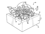
- FIG. 1A illustrates cross sectional view of a structure on an inventive metal current collector for electrodes of opposite polarity wherein particles of an active material are represented by crystals or amorphous particles interconnected with a multitude of other particles of circular shape representing accreted and crystallized drops of melted metal current collector;
- FIG. 1B illustrates a perspective view of the structure of the metal current collector of an electrode of FIG. 1A ;
- FIG. 2A illustrates is a perspective and segmental view of the metal current collector of the electrode and the first particles colliding therewith thereby melting the metal current collector with some particles partially entering the metal current collector;
- FIG. 2B is a partially cross sectional view of the electrode having the metal current collector of FIG. 2A ;
- FIG. 2C illustrates is a perspective and segmental view of the metal current collector and the first particles disposed inside the metal current collector with the areas of local melting of current collector shown in phantom;
- FIG. 2D is a partially cross sectional view of the metal current collector of FIG. 2C with the first particles shown in phantom;
- FIG. 2E illustrates is a perspective and segmental view of the metal current collector and the metal drops splashed from the metal current collector as in response to the impact of the first particles against the metal current collector and applying ultrasonic vibration;
- FIG. 2F is a partially cross sectional view of the electrode of FIG. 2E ;
- FIG. 2G illustrates is a perspective and segmental view of the metal current collector and the metal drops solidified in the shaped of the second particles and interconnected with the first particles to form a grid of a porous structure of an active core inside the metal current collector;
- FIG. 2H is a partially cross sectional view of the metal current collector of FIG. 2G ;
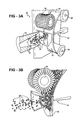
- FIG. 3A illustrates a perspective view of an apparatus for forming the electrode having the metal current collector disposed therein;
- FIG. 3B illustrated a fragmental view of the apparatus shown in FIG. 3A ;
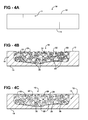
- FIGS. 4A through 4E illustrate various cross sectional view of the metal current collector of the present invention as the metal current collector is moved along an assembly path with the active core being formed inside the metal current collector;
- FIG. 5 shows a schematic vie of the assembly of the cell by combining the electrodes of opposite polarity with each electrode having inventive active core inside the current collector;
- FIG. 6A illustrate various microscopic views of fracture of the inventive electrode to clearly illustrate the first and second nano-particles of the active core with each of the particles having nano-dimensions;
- FIG. 6B illustrate the cross section structure of initial aluminum current collector before the active material deposition
- FIG. 6C illustrate the cross section structure of the electrode with the active layer deposited inside current collector shown in the FIG. 6B ;
- FIG. 7 presents a graph illustrating electrochemical testing results of the cell having a cathode electrode formed according to the present invention.
- FIG. 8A is a perspective view of at least one configuration of the inventive cell
- FIGS. 8B and 8C show a microscopic views of the cross section of the thin cell with at least one electrode formed according to present invention.
- FIG. 9 presents another graph illustrating electrochemical testing results of the cell having at least one electrode formed according to the present invention.
- an electrode of the present invention is generally shown at 10 .
- the electrode 10 of the present invention is formed from a metallic tape, generally indicated at 11 and shown fragmentally in FIGS. 1A to 2H , is used to form a first electrode such as an anode and a second electrode such as cathode, both illustrated at A and C, respectively, in FIGS. 5 and 8B and 8 C, and spaced by a separator S and combined into a cell, generally indicated at 13 in FIG. 8A , for producing electric power without limiting the scope of the present invention.
- the metal current collector 11 of the first electrode and the second electrode has opposed sides 12 and 14 defining an initial thickness 16 , as best illustrated in a cross sectional view shown in FIG. 1A .
- An active core, generally shown at 18 in FIG. 1A is formed inside the metal current collector 10 .
- the active core 18 is formed from first particles 20 being integral with and extending from the metal current collector 11 of at least one of the first and second electrodes.
- the first particles 20 are formed as the second particle 22 , impacting the metal current collector 11 , as best shown in FIGS. 2A and 2B , resulting in local increased temperature of the metal current collector 11 , which locally melts, as shown in FIGS. 2C and 2D , as the second particles 22 are at least partially penetrate the metal current collector 11 .
- the impact of the second particles 22 onto the melted metal current collector 11 results in multitude of aerosol drops 24 separated from the metal current collector 11 , as best illustrated in FIGS. 2E and 2F .
- the active core 18 is formed in response to solidification of the aerosol drops 24 , which follows local melting and ultrasonic cavitations of the metal current collector 11 thereby forming the first particles 20 .
- the first particles 20 are integral with the metal current collector and present circular or globular configuration, as view in a cross section.
- the second particles are formed from of active material, other that the metal current collector 11 , and may present a rectangular configuration, or other configuration, and the like, as best shown in FIGS.
- the active material of the second particles 22 includes and not limited to silicon, carbon, germanium, oxides, salts, ceramic components, LiCoO 2 , LiMn 2 O 4 , LiFePO 4 , MnO 2 , Li, Si, C, Ge, SnO, SnO 2 , and the like, without limiting the scope of the present invention.
- the first and second particles 20 and 22 are connected with one another to form a porous grid, generally indicated at 32 in FIGS. 1A and 1B of a three dimensional configuration of the active core 18 disposed inside the metal current collector 11 thereby resulting in the metal current collector 11 being integral with the active core 18 and presenting a second thickness 34 .
- the grid 32 is further defined by the first particles 20 being continuously connected with the metal current collector 11 thereby eliminating sharp interface between the grid 32 and the metal current collector 11 .
- the first particles 20 are connected to the second particles 22 and the metal current collector 11 in a diffusible fashion with the second particles 22 being at least partially exposed through and beyond the grid 32 .
- the second particles 22 are inside the grid 32 of the active core 18 and do not exposed beyond the active core 18 .
- the first particles 20 and the second particles 22 are free from low conductivity films at interface defined between the first and second particles 20 and 22 and the metal current collector 11 .
- the first particles 20 are fused with one and the other thereby forming an inter-layered structure of the grid 32 with the second particles 22 disposed therebetween.
- the second particles 22 and the metal current collector 11 define points of contacts having a thermal decomposition temperature being lower than a melting temperature of the first particles 20 .
- the second particles 22 present a size ranging from at least 50 nm and up to 500 nm.
- the first particles 20 present a size ranging from at least 5 nm and up to 100 nm.
- the second thickness 34 may be substantially the same or smaller than the first thickness 16 .
- the grid 32 presents a plurality of pores, only some of the pores are shown at 36 in FIG. 1A .
- the grid 32 may present 60 percent of the pores 36 and 40 percent of the first and second particles 20 and 22 of a total volume of the active core 18 . This ratio is not intended to limit the scope of the present invention.
- the pores 36 may present up to 80 percent of the active core 18 or only 0.55 percent of the active core 18 . This ratio is not intended to limit the scope of the present invention.
- the active core 18 is mixed with and covered by an electrolyte, as best shown at 38 in FIG. 4C .
- the electrolyte 38 may be liquid or non-liquid.
- one of the advantages of the present invention is the absence of an oxide film at contact points the first and second particles 20 and 22 , which reduces electronic resistance at the interface of the cathode's C active substance and metal binding.
- Multitude of contact points defined between the particles 20 and 22 and the metal current collector 11 expose the greater part of the active core 18 open to electrochemical interaction with the electrolyte.
- the size of the first particles 20 as viewed in cross section is between 5 to 100 nm.
- the size of the second particles 22 formed from the active substance is between 50 to 500 nm.
- the first particles 20 and the metal current collector 10 with the second particles 22 of the active material is 25-32 per square micron of particle surface, thereby providing reliable and improved outlet of electrons to the metal current collector 10 during cyclic changes in active substance particle size during reversible electrode operation in the cell 13 .
- the three-dimensional grid 32 has low thickness and the second particles 22 of form the dense one layer film on the electrode surface.
- FIGS. 3A and 3B illustrate fragmental view of the inventive apparatus 40 of the present invention, which is described in great details in the patent application serial number incorporated herewith in its entirety.
- FIGS. 3A and 3B illustrate a nozzle 42 through which the second particles 22 of the active material are injected onto the tape 44 of the electrode 10 rolled between a pair of rollers 46 and 48 .
- An ultrasonic vibrator, generally shown at 45 in FIGS. 3A and 3B is positioned to abut the inner side of the tape 44 .
- the functional aspects and purpose of the ultrasonic vibrator 45 are disclosed in the patent application Ser. No. 11/560,922 incorporated herewith by reference in its entirety.
- a brush 50 is positioned adjacent the tape 44 to extract excess of the first and second particles 20 and 22 .
- FIGS. 4A through 4E illustrate various cross sectional view of the electrode 10 of the present invention as the metal current collector 11 is moved along an assembly path with the active core 18 being formed inside the metal current collector 11 .
- a layer of isolating bar 60 is continuously disposed about one of the opposed sides 12 of the electrode 10 of at least one of the first and second electrodes.
- the electrode 10 can be an anode and can also include an anode layer 62 formed from lithium covering the active core 18 to extend co-planarly with the layer of isolating bar 60 .
- an anode current collector 64 formed from copper, nickel or other metal can extend over the anode layer 62 and the layer of the isolating bar 60 .
- An isolating layer 66 extends over the anode current collector 64 sandwiched between the anode layer 62 and the isolating layer 66 .
- the structure of the electrode 10 as set forth above is applicable to both the anode A and the cathode C of the present invention.
- FIGS. 8B and 8C illustrate a cross section of the cell includes the anode A and the cathode C formed by the method of the present invention, clearly illustrating the dimensions of the anode A of 15 ⁇ m, the cathode of 9 ⁇ m, and the separator S of 10 ⁇ m.
- the table shown further below illustrates dimensions and technical characteristics of the preferred embodiment of the cell 13 of the present invention. However, these dimensions are illustrated for exemplary purposes as one of the embodiment of the present invention and are not intended to limit the scope of the present invention.
- an assembly “roll to roll” process of the present invention is generally shown at 68 .
- the cathode C and the anode A are rolled from two spaced drums 70 and 72 along an assembly path 74 with the metal current collector 10 of each of the cathode C and the anode A facing one another.
- An electrolyte with separator (if necessary) 76 either liquid or non-liquid is injected between the cathode C and the anode A in addition to the electrolyte 38 of the metal current collector 10 .
- a heating element (not shown) is adjacent the assembly path 74 to heat the electrolyte 76 thereby improving polymerization of the electrolyte 76 .
- a pair of cutting devices 82 and 84 disposed on both sides of the assembly path 74 are cutting the assembled cathode C and the anode A to a multitude of prefabricated cells 13 .
- Numerous mechanical, laser, and electrical devices are used as cutting devices 82 and 84 and are not intended to limit the scope of the present invention.
- the cells 13 are sealed hermetically along the peripheral edge or the periphery 86 .
- FIGS. 6A through 6C illustrate various cross section microscopic views to clearly illustrate the first and second nano-particles 20 and 22 of the active core 18 with each of the particles having nano-dimensions.
- FIG. 7 presents a graph illustrating electrochemical testing results of cathode electrode 10 formed according to the invention.
- FIG. 8A is a perspective view of at least one configuration of the inventive cell.
- FIGS. 8B and 8C show cross section microscopic views of the electrodes of opposite polarity with at least one electrode formed according to the invention.
- FIG. 9 presents another graph illustrating electrochemical testing results of the cell shown in the FIGS. 8 A-C having at least one electrode made according to the present invention.
- the electrode 10 and the method of forming the same have numerous valuable advantages of the prior art electrodes and methods.
- One of the advantages for example, is the unique structure of the electrode 10 wherein the active core 18 is formed in an organic binder free fashion, i.e. by the inventive method of solidification of the aerosol drops 24 of the metal current collector 10 and the particles 22 of active material while maintaining adhesion therebetween.
- Another advantage of the present invention is to provide a unique method for fabricating the electrodes A and/or C wherein the metal current collector 10 presents nano-structured surface, has low thermal stability and improved cycling life.
- the unique method of forming the electrodes A and/or C utilizes the high-pressure deposition solidification method wherein the particles 22 of the active material and the solidified drops 24 are formed as a result of the formation of the aerosol mixture form the grid 32 presenting a continuous surface of the metal current collector 10 of the electrodes A and/or C.
- the present inventive concept has various applications including and not limited to high efficiency thin-film photovoltaic solar cells for cost-effective renewable energy, fuel cell components such as catalytic membranes for environmentally friendly power supplies, super capacitors for smaller and lighter portable handheld devices such as cell phones, laptops, thin film sensors for more effective monitoring and control of temperature, illumination, and humidity, high-conductivity wires with low resistance adaptable for manufacturing of a wide variety of electronic devices, and the like.
Abstract
Description
| Cathode - Al current collector | Thickness, μm | 9 | |
| with active substance LiMn2O4 | Δm, mg/cm2 | 0.7-0.9 | |
| Separator + polymer electrolyte | Thickness, μm | 10-16 | |
| Anode - Cu current collector with Li | Thickness, μm | 15 | |
| Total of | Expectancy | 40 | |
| Thickness, μm | |||
| Real Thickness, μm | 50 | ||
| See Ris. 2. | |||
| Capacity, mAh/cm2 | 0.07-0.09 | ||
| at low current | |||
| Volume, cm3 | 0.01 | ||
| Capacity, mAh at | 0.18 | ||
| low current | |||
| discharge | |||
| Average voltage, | 3.9 | ||
| V at low current | |||
| discharge | |||
| Energy density Wh/ |
70 | ||
| Peak Power W/l | >500 | ||
Claims (6)
Priority Applications (7)
| Application Number | Priority Date | Filing Date | Title |
|---|---|---|---|
| US11/561,077 US7972731B2 (en) | 2006-03-08 | 2006-11-17 | Electrode for cell of energy storage device and method of forming the same |
| CN2007800498763A CN101617420B (en) | 2006-11-17 | 2007-11-19 | Electrode for cell of energy storage device and method of forming the same |
| PCT/US2007/024268 WO2008133657A2 (en) | 2006-11-17 | 2007-11-19 | Electrode for cell of energy storage device |
| RU2009122972/07A RU2444816C2 (en) | 2006-11-17 | 2007-11-19 | Electrode for cell of energy-accumulating device and method of its manufacturing |
| EP07874139A EP2109905A4 (en) | 2006-11-17 | 2007-11-19 | Electrode for cell of energy storage device and method of forming the same |
| CA2689981A CA2689981A1 (en) | 2006-11-17 | 2007-11-19 | Electrode for cell of energy storage device and method of forming the same |
| KR1020097012609A KR20090105915A (en) | 2006-11-17 | 2007-11-19 | Electrode for cell of energy storage device and method of forming the same |
Applications Claiming Priority (3)
| Application Number | Priority Date | Filing Date | Title |
|---|---|---|---|
| US78024006P | 2006-03-08 | 2006-03-08 | |
| US11/560,922 US7717968B2 (en) | 2006-03-08 | 2006-11-17 | Electrode for energy storage device and method of forming the same |
| US11/561,077 US7972731B2 (en) | 2006-03-08 | 2006-11-17 | Electrode for cell of energy storage device and method of forming the same |
Related Parent Applications (1)
| Application Number | Title | Priority Date | Filing Date |
|---|---|---|---|
| US11/560,922 Continuation-In-Part US7717968B2 (en) | 2006-03-08 | 2006-11-17 | Electrode for energy storage device and method of forming the same |
Publications (2)
| Publication Number | Publication Date |
|---|---|
| US20070224513A1 US20070224513A1 (en) | 2007-09-27 |
| US7972731B2 true US7972731B2 (en) | 2011-07-05 |
Family
ID=39926233
Family Applications (1)
| Application Number | Title | Priority Date | Filing Date |
|---|---|---|---|
| US11/561,077 Expired - Fee Related US7972731B2 (en) | 2006-03-08 | 2006-11-17 | Electrode for cell of energy storage device and method of forming the same |
Country Status (7)
| Country | Link |
|---|---|
| US (1) | US7972731B2 (en) |
| EP (1) | EP2109905A4 (en) |
| KR (1) | KR20090105915A (en) |
| CN (1) | CN101617420B (en) |
| CA (1) | CA2689981A1 (en) |
| RU (1) | RU2444816C2 (en) |
| WO (1) | WO2008133657A2 (en) |
Cited By (1)
| Publication number | Priority date | Publication date | Assignee | Title |
|---|---|---|---|---|
| US20140146439A1 (en) * | 2012-11-27 | 2014-05-29 | Samsung Electro-Mechanics Co., Ltd. | Electrode structure and method for manufacturing the same, and energy storage device including the electrode structure |
Families Citing this family (22)
| Publication number | Priority date | Publication date | Assignee | Title |
|---|---|---|---|---|
| GB2395059B (en) | 2002-11-05 | 2005-03-16 | Imp College Innovations Ltd | Structured silicon anode |
| GB0601318D0 (en) | 2006-01-23 | 2006-03-01 | Imp Innovations Ltd | Method of etching a silicon-based material |
| GB0601319D0 (en) * | 2006-01-23 | 2006-03-01 | Imp Innovations Ltd | A method of fabricating pillars composed of silicon-based material |
| US7951242B2 (en) * | 2006-03-08 | 2011-05-31 | Nanoener Technologies, Inc. | Apparatus for forming structured material for energy storage device and method |
| GB0709165D0 (en) | 2007-05-11 | 2007-06-20 | Nexeon Ltd | A silicon anode for a rechargeable battery |
| GB0713895D0 (en) * | 2007-07-17 | 2007-08-29 | Nexeon Ltd | Production |
| GB0713898D0 (en) | 2007-07-17 | 2007-08-29 | Nexeon Ltd | A method of fabricating structured particles composed of silcon or a silicon-based material and their use in lithium rechargeable batteries |
| GB0713896D0 (en) * | 2007-07-17 | 2007-08-29 | Nexeon Ltd | Method |
| GB2464157B (en) | 2008-10-10 | 2010-09-01 | Nexeon Ltd | A method of fabricating structured particles composed of silicon or a silicon-based material |
| GB2464158B (en) | 2008-10-10 | 2011-04-20 | Nexeon Ltd | A method of fabricating structured particles composed of silicon or a silicon-based material and their use in lithium rechargeable batteries |
| GB2470056B (en) | 2009-05-07 | 2013-09-11 | Nexeon Ltd | A method of making silicon anode material for rechargeable cells |
| GB2470190B (en) | 2009-05-11 | 2011-07-13 | Nexeon Ltd | A binder for lithium ion rechargeable battery cells |
| US9853292B2 (en) | 2009-05-11 | 2017-12-26 | Nexeon Limited | Electrode composition for a secondary battery cell |
| GB201005979D0 (en) | 2010-04-09 | 2010-05-26 | Nexeon Ltd | A method of fabricating structured particles composed of silicon or a silicon-based material and their use in lithium rechargeable batteries |
| GB201009519D0 (en) | 2010-06-07 | 2010-07-21 | Nexeon Ltd | An additive for lithium ion rechargeable battery cells |
| GB201014706D0 (en) | 2010-09-03 | 2010-10-20 | Nexeon Ltd | Porous electroactive material |
| GB201014707D0 (en) | 2010-09-03 | 2010-10-20 | Nexeon Ltd | Electroactive material |
| CA2835915A1 (en) * | 2011-05-13 | 2012-11-22 | East Penn Manufacturing Co. | Composite current collector and methods therefor |
| DE102012224377A1 (en) * | 2012-12-27 | 2014-07-03 | Robert Bosch Gmbh | Method for producing a galvanic element and galvanic element |
| DE102013203280A1 (en) | 2013-02-27 | 2014-08-28 | Bayerische Motoren Werke Aktiengesellschaft | High-voltage energy storage module and method for producing the high-voltage energy storage module |
| JP6794965B2 (en) * | 2017-09-01 | 2020-12-02 | トヨタ自動車株式会社 | Electrode manufacturing equipment and manufacturing method |
| WO2023278318A1 (en) * | 2021-07-02 | 2023-01-05 | Sion Power Corporation | Solid-state electrochemical cell components and related systems and methods |
Citations (22)
| Publication number | Priority date | Publication date | Assignee | Title |
|---|---|---|---|---|
| US4815414A (en) | 1987-04-20 | 1989-03-28 | Nylok Fastener Corporation | Powder spray apparatus |
| US5302414A (en) | 1990-05-19 | 1994-04-12 | Anatoly Nikiforovich Papyrin | Gas-dynamic spraying method for applying a coating |
| US5795680A (en) * | 1995-11-30 | 1998-08-18 | Asahi Glass Company Ltd. | Non-aqueous electrolyte type secondary battery |
| US6402050B1 (en) | 1996-11-13 | 2002-06-11 | Alexandr Ivanovich Kashirin | Apparatus for gas-dynamic coating |
| US6475664B1 (en) * | 1999-09-09 | 2002-11-05 | Canon Kabushiki Kaisha | Alkali rechargeable batteries and process for the production of said rechargeable batteries |
| US20020177032A1 (en) | 2001-03-28 | 2002-11-28 | Kabushiki Kaisha Toshiba | Fuel cell, electrode for fuel cell and a method of manufacturing the same |
| US6544689B1 (en) * | 1999-06-30 | 2003-04-08 | North Carolina State University | Composite electrolytes based on smectite clays and high dielectric organic liquids and electrodes |
| US20030203282A1 (en) | 2002-04-29 | 2003-10-30 | Sylvie Grugeon | Nano-metal electrode rechargeable battery cell |
| US6679926B1 (en) * | 1999-06-11 | 2004-01-20 | Kao Corporation | Lithium secondary cell and its producing method |
| US6706431B2 (en) | 2000-11-14 | 2004-03-16 | Fullerene Usa, Inc. | Fuel cell |
| US6761744B1 (en) | 1999-07-16 | 2004-07-13 | Quallion Llc | Lithium thin film lamination technology on electrode to increase battery capacity |
| US20040137326A1 (en) | 2002-11-09 | 2004-07-15 | Munshi M. Zafar A. | Lithium ion battery and methods of manufacturing same |
| US20040185343A1 (en) | 2003-01-30 | 2004-09-23 | Liya Wang | Composite material and electrodes made therefrom |
| US20040191607A1 (en) | 2003-03-27 | 2004-09-30 | Tomoki Nobuta | Electrode and electrochemical cell therewith |
| US6800399B2 (en) | 2000-08-30 | 2004-10-05 | Isao Matsumoto | Non-sintered thin electrode for battery, battery using same and process for same |
| US20040197654A1 (en) | 2003-04-03 | 2004-10-07 | Jeremy Barker | Electrodes comprising mixed active particles |
| US20040202937A1 (en) | 2001-10-09 | 2004-10-14 | Jeremy Barker | Lithiated molybdenum oxide active Materials |
| US20040248010A1 (en) | 2003-06-09 | 2004-12-09 | Matsushita Electric Industrial Co., Ltd. | Lithium-ion rechargeable battery |
| WO2005006469A1 (en) * | 2003-07-15 | 2005-01-20 | Itochu Corporation | Current collecting structure and electrode structure |
| US20050191555A1 (en) | 2002-06-28 | 2005-09-01 | Firefly Energy Inc. | Battery including carbon foam current collectors |
| JP2006059641A (en) | 2004-08-19 | 2006-03-02 | Nissan Motor Co Ltd | Electrode for secondary battery and secondary battery using it |
| US20060051677A1 (en) | 2004-09-09 | 2006-03-09 | Mitsui Mining & Smelting Co., Ltd. | Negative electrode for nonaqueous secondary battery |
Family Cites Families (1)
| Publication number | Priority date | Publication date | Assignee | Title |
|---|---|---|---|---|
| RU2098895C1 (en) * | 1995-05-17 | 1997-12-10 | Общество с ограниченной ответственностью "Интергрин" | Nickel-iron storage cell |
-
2006
- 2006-11-17 US US11/561,077 patent/US7972731B2/en not_active Expired - Fee Related
-
2007
- 2007-11-19 WO PCT/US2007/024268 patent/WO2008133657A2/en active Application Filing
- 2007-11-19 RU RU2009122972/07A patent/RU2444816C2/en not_active IP Right Cessation
- 2007-11-19 KR KR1020097012609A patent/KR20090105915A/en not_active Application Discontinuation
- 2007-11-19 EP EP07874139A patent/EP2109905A4/en not_active Withdrawn
- 2007-11-19 CA CA2689981A patent/CA2689981A1/en not_active Abandoned
- 2007-11-19 CN CN2007800498763A patent/CN101617420B/en not_active Expired - Fee Related
Patent Citations (24)
| Publication number | Priority date | Publication date | Assignee | Title |
|---|---|---|---|---|
| US4815414A (en) | 1987-04-20 | 1989-03-28 | Nylok Fastener Corporation | Powder spray apparatus |
| US5302414A (en) | 1990-05-19 | 1994-04-12 | Anatoly Nikiforovich Papyrin | Gas-dynamic spraying method for applying a coating |
| US5302414B1 (en) | 1990-05-19 | 1997-02-25 | Anatoly N Papyrin | Gas-dynamic spraying method for applying a coating |
| US5795680A (en) * | 1995-11-30 | 1998-08-18 | Asahi Glass Company Ltd. | Non-aqueous electrolyte type secondary battery |
| US6402050B1 (en) | 1996-11-13 | 2002-06-11 | Alexandr Ivanovich Kashirin | Apparatus for gas-dynamic coating |
| US6679926B1 (en) * | 1999-06-11 | 2004-01-20 | Kao Corporation | Lithium secondary cell and its producing method |
| US6544689B1 (en) * | 1999-06-30 | 2003-04-08 | North Carolina State University | Composite electrolytes based on smectite clays and high dielectric organic liquids and electrodes |
| US6761744B1 (en) | 1999-07-16 | 2004-07-13 | Quallion Llc | Lithium thin film lamination technology on electrode to increase battery capacity |
| US6475664B1 (en) * | 1999-09-09 | 2002-11-05 | Canon Kabushiki Kaisha | Alkali rechargeable batteries and process for the production of said rechargeable batteries |
| US6800399B2 (en) | 2000-08-30 | 2004-10-05 | Isao Matsumoto | Non-sintered thin electrode for battery, battery using same and process for same |
| US6706431B2 (en) | 2000-11-14 | 2004-03-16 | Fullerene Usa, Inc. | Fuel cell |
| US20020177032A1 (en) | 2001-03-28 | 2002-11-28 | Kabushiki Kaisha Toshiba | Fuel cell, electrode for fuel cell and a method of manufacturing the same |
| US20040202937A1 (en) | 2001-10-09 | 2004-10-14 | Jeremy Barker | Lithiated molybdenum oxide active Materials |
| US20030203282A1 (en) | 2002-04-29 | 2003-10-30 | Sylvie Grugeon | Nano-metal electrode rechargeable battery cell |
| US20050191555A1 (en) | 2002-06-28 | 2005-09-01 | Firefly Energy Inc. | Battery including carbon foam current collectors |
| US20040137326A1 (en) | 2002-11-09 | 2004-07-15 | Munshi M. Zafar A. | Lithium ion battery and methods of manufacturing same |
| US20040185343A1 (en) | 2003-01-30 | 2004-09-23 | Liya Wang | Composite material and electrodes made therefrom |
| US20040191607A1 (en) | 2003-03-27 | 2004-09-30 | Tomoki Nobuta | Electrode and electrochemical cell therewith |
| US20040197654A1 (en) | 2003-04-03 | 2004-10-07 | Jeremy Barker | Electrodes comprising mixed active particles |
| US20040248010A1 (en) | 2003-06-09 | 2004-12-09 | Matsushita Electric Industrial Co., Ltd. | Lithium-ion rechargeable battery |
| WO2005006469A1 (en) * | 2003-07-15 | 2005-01-20 | Itochu Corporation | Current collecting structure and electrode structure |
| US20060175704A1 (en) * | 2003-07-15 | 2006-08-10 | Tatsuo Shimizu | Current collecting structure and electrode structure |
| JP2006059641A (en) | 2004-08-19 | 2006-03-02 | Nissan Motor Co Ltd | Electrode for secondary battery and secondary battery using it |
| US20060051677A1 (en) | 2004-09-09 | 2006-03-09 | Mitsui Mining & Smelting Co., Ltd. | Negative electrode for nonaqueous secondary battery |
Cited By (2)
| Publication number | Priority date | Publication date | Assignee | Title |
|---|---|---|---|---|
| US20140146439A1 (en) * | 2012-11-27 | 2014-05-29 | Samsung Electro-Mechanics Co., Ltd. | Electrode structure and method for manufacturing the same, and energy storage device including the electrode structure |
| US9093224B2 (en) * | 2012-11-27 | 2015-07-28 | Samsung Electro-Mechanics Co., Ltd. | Electrode structure and method for manufacturing the same, and energy storage device including the electrode structure |
Also Published As
| Publication number | Publication date |
|---|---|
| KR20090105915A (en) | 2009-10-07 |
| RU2444816C2 (en) | 2012-03-10 |
| EP2109905A2 (en) | 2009-10-21 |
| CA2689981A1 (en) | 2008-11-06 |
| WO2008133657A3 (en) | 2008-12-31 |
| EP2109905A4 (en) | 2012-03-28 |
| US20070224513A1 (en) | 2007-09-27 |
| RU2009122972A (en) | 2010-12-27 |
| WO2008133657A2 (en) | 2008-11-06 |
| CN101617420A (en) | 2009-12-30 |
| CN101617420B (en) | 2013-04-10 |
Similar Documents
| Publication | Publication Date | Title |
|---|---|---|
| US7972731B2 (en) | Electrode for cell of energy storage device and method of forming the same | |
| US9356281B2 (en) | Intercalation electrode based on ordered graphene planes | |
| EP2965369B1 (en) | Solid-state battery separators and methods of fabrication | |
| US8142569B2 (en) | Apparatus for forming structured material for energy storage device and method | |
| JP5687491B2 (en) | Electrode and manufacturing method thereof | |
| EP2387805B1 (en) | A process for producing carbon nanostructure on a flexible substrate, and energy storage devices comprising flexible carbon nanostructure electrodes | |
| Yu et al. | Three-dimensional porous amorphous SnO2 thin films as anodes for Li-ion batteries | |
| EP3098882B1 (en) | Electrical device | |
| EP2418720B1 (en) | Collector for secondary battery, and secondary battery using same | |
| US20160308243A1 (en) | Electrochemical cell with solid and liquid electrolytes | |
| JP2000311681A (en) | Negative electrode material for secondary battery, electrode structural body, secondary battery and their manufacture | |
| EP3098892B1 (en) | Electrical device | |
| US20160336593A1 (en) | Electrical device | |
| CA2783974C (en) | High performance energy storage and collection devices containing exfoliated microtubules and spatially controlled attached nanoscale particles and layers | |
| JP2015082374A (en) | Method for manufacturing electrode, electrode of secondary battery, and secondary battery using the same | |
| EP3098890B1 (en) | Electrical device | |
| KR100866863B1 (en) | Anode for rechargeable lithium secondary battery, method of preparing thereof, and rechargeable lithium secondary battery comprising the same | |
| KR20170032905A (en) | Carbon nanotube-based lithium ion battery | |
| Kang et al. | Highly stable lithium metal anode enabled by constructing lithiophilic 3D interphase on robust framework | |
| JP2024507490A (en) | Long cycle life, high capacity silicon anodes and methods of making and using the same | |
| JP4626966B2 (en) | ELECTRODE FOR LITHIUM SECONDARY BATTERY AND METHOD FOR PRODUCING THE SAME | |
| CN116505097A (en) | Composite structure and application thereof |
Legal Events
| Date | Code | Title | Description |
|---|---|---|---|
| AS | Assignment |
Owner name: NANOENER TECHNOLOGIES, INC., FLORIDA Free format text: ASSIGNMENT OF ASSIGNORS INTEREST;ASSIGNOR:NOVAK, PETER;REEL/FRAME:025703/0850 Effective date: 20091113 |
|
| AS | Assignment |
Owner name: ENER1, INC., NEW YORK Free format text: ASSIGNMENT OF ASSIGNORS INTEREST;ASSIGNOR:KALYNUSHKIN, YEVGEN;REEL/FRAME:025783/0111 Effective date: 20050707 |
|
| STCF | Information on status: patent grant |
Free format text: PATENTED CASE |
|
| AS | Assignment |
Owner name: BZINFIN S.A., SWITZERLAND Free format text: SECURITY AGREEMENT;ASSIGNORS:ENERDEL, INC.;ENERFUEL, INC.;ENER1, INC.;AND OTHERS;REEL/FRAME:027370/0979 Effective date: 20111116 |
|
| AS | Assignment |
Owner name: ENER1, INC., INDIANA Free format text: TERMINATION AND RELEASE OF SECURITY INTEREST IN PATENTS;ASSIGNOR:BZINFIN, S.A.;REEL/FRAME:027982/0854 Effective date: 20120330 Owner name: ENERFUEL, INC., FLORIDA Free format text: TERMINATION AND RELEASE OF SECURITY INTEREST IN PATENTS;ASSIGNOR:BZINFIN, S.A.;REEL/FRAME:027982/0854 Effective date: 20120330 Owner name: NANO ENER, INC., FLORIDA Free format text: TERMINATION AND RELEASE OF SECURITY INTEREST IN PATENTS;ASSIGNOR:BZINFIN, S.A.;REEL/FRAME:027982/0854 Effective date: 20120330 Owner name: ENERDEL, INC., ILLINOIS Free format text: TERMINATION AND RELEASE OF SECURITY INTEREST IN PATENTS;ASSIGNOR:BZINFIN, S.A.;REEL/FRAME:027982/0854 Effective date: 20120330 |
|
| AS | Assignment |
Owner name: WILMINGTON TRUST, NATIONAL ASSOCIATION, MINNESOTA Free format text: PATENT SECURITY AGREEMENT;ASSIGNORS:ENER1, INC.;ENERDEL, INC.;ENERFUEL, INC.;AND OTHERS;REEL/FRAME:027999/0516 Effective date: 20120330 |
|
| AS | Assignment |
Owner name: NANOENER, INC., INDIANA Free format text: RELEASE BY SECURED PARTY;ASSIGNOR:WILMINGTON TRUST, NATIONAL ASSOCIATION, AS COLLATERAL AGENT;REEL/FRAME:030461/0932 Effective date: 20130517 |
|
| AS | Assignment |
Owner name: ENMAT GLOBAL, LLC, INDIANA Free format text: ASSIGNMENT OF ASSIGNORS INTEREST;ASSIGNOR:NANOENER, INC.;REEL/FRAME:030954/0195 Effective date: 20130528 |
|
| FEPP | Fee payment procedure |
Free format text: PAT HOLDER CLAIMS SMALL ENTITY STATUS, ENTITY STATUS SET TO SMALL (ORIGINAL EVENT CODE: LTOS); ENTITY STATUS OF PATENT OWNER: SMALL ENTITY |
|
| FPAY | Fee payment |
Year of fee payment: 4 |
|
| FEPP | Fee payment procedure |
Free format text: MAINTENANCE FEE REMINDER MAILED (ORIGINAL EVENT CODE: REM.); ENTITY STATUS OF PATENT OWNER: SMALL ENTITY |
|
| LAPS | Lapse for failure to pay maintenance fees |
Free format text: PATENT EXPIRED FOR FAILURE TO PAY MAINTENANCE FEES (ORIGINAL EVENT CODE: EXP.); ENTITY STATUS OF PATENT OWNER: SMALL ENTITY |
|
| STCH | Information on status: patent discontinuation |
Free format text: PATENT EXPIRED DUE TO NONPAYMENT OF MAINTENANCE FEES UNDER 37 CFR 1.362 |
|
| FP | Lapsed due to failure to pay maintenance fee |
Effective date: 20190705 |