EP1113111A1 - Concrete breaking shear - Google Patents
Concrete breaking shear Download PDFInfo
- Publication number
- EP1113111A1 EP1113111A1 EP99811219A EP99811219A EP1113111A1 EP 1113111 A1 EP1113111 A1 EP 1113111A1 EP 99811219 A EP99811219 A EP 99811219A EP 99811219 A EP99811219 A EP 99811219A EP 1113111 A1 EP1113111 A1 EP 1113111A1
- Authority
- EP
- European Patent Office
- Prior art keywords
- jaw
- cutting
- concrete
- teeth
- pliers
- Prior art date
- Legal status (The legal status is an assumption and is not a legal conclusion. Google has not performed a legal analysis and makes no representation as to the accuracy of the status listed.)
- Granted
Links
Images


Classifications
-
- E—FIXED CONSTRUCTIONS
- E02—HYDRAULIC ENGINEERING; FOUNDATIONS; SOIL SHIFTING
- E02F—DREDGING; SOIL-SHIFTING
- E02F3/00—Dredgers; Soil-shifting machines
- E02F3/04—Dredgers; Soil-shifting machines mechanically-driven
- E02F3/96—Dredgers; Soil-shifting machines mechanically-driven with arrangements for alternate or simultaneous use of different digging elements
- E02F3/965—Dredgers; Soil-shifting machines mechanically-driven with arrangements for alternate or simultaneous use of different digging elements of metal-cutting or concrete-crushing implements
Definitions
- the present invention relates to a concrete crusher according to the preamble of claim 1.
- Such concrete crushing tongs are used to break off structures made of reinforced concrete.
- the pliers move the concrete crusher on the one hand the concrete is broken and on the other hand in the same sequence of movements the reinforcing iron is cut.
- Such concrete crushing tongs are known.
- EP-B-0 770 164 shows such a concrete crusher.
- This concrete crusher has two jaws, each with concrete breaking areas and cutting edges are provided.
- the concrete crushing areas are over the Cutting edges protruding, which is to avoid breaking of the concrete is triggered by the cutting edges used to cut the Reinforcing iron are provided and therefore have a relatively sharp edge should.
- the breaking edge and the cutting edge are all-round, i.e. In order to be able to optimally cut the reinforcing bars, the concrete breaking edge may do not protrude too much beyond the cutting edge. This allows do not avoid cutting edge by breaking the concrete is heavily used, which can result in severe wear and tear expresses itself in declining cut quality for the reinforcing iron.
- first cutting elements each of which is made of a are formed with a bend block on the side areas the first jaw and the second jaw.
- Another advantageous embodiment of the invention consists in that a guide rib on the convex surface of the previously described block is attached, which is aligned in the longitudinal direction to the convex surface is and runs in the middle, the respective support surface of the receiving pocket is equipped with a groove corresponding to the guide rib, in which the guide rib in the inserted state of the block in the pliers jaw intervenes.
- the block is optimally in the pocket of the respective jaws.
- Another advantageous embodiment of the invention consists in that elements at the end regions of the support surfaces of the receiving pockets are attached, which are provided with stop surfaces on which the End faces of the blocks are in the inserted state in the receiving pockets are.
- the jaws on each side area two each arranged in series, formed by the blocks Cutting elements are provided, which can be screwed onto the jaw of the pliers Teeth are kept in the receiving pockets.
- the tips of the teeth are protruding beyond the cutting edges of the cutting elements, causing breaking of the concrete is at least introduced through these teeth and the Cutting edges are thus protected.
- Another advantageous embodiment of the invention consists in that the bend of the block forming the cutting elements is circular is, which makes the contact surface optimal and the production of the blocks and the Recording bags is simplified.
- the one between the two cutting edges lying concave surface of the blocks has a curvature and the wedge angle the cutting edge becomes larger than 90 °.
- Another advantageous embodiment of the invention consists in that at the front area of the first and the second jaws of each a plate forming the second cutting element is attached, each with a side surface on a corresponding support surface of the receiving pocket rests and thus optimal power transmission to the jaws is achieved becomes.
- This plate is supported on the support surface adjacent wall of the first jaw or the second jaw and is screwed against it. So this plate is also easier Way interchangeable.
- the two side surfaces of the plate are advantageously provided with indentations and protrusions along which the cutting edge runs.
- the plate can be inserted into the receiving pocket in such a way that one or the other of the two cutting edges is in use. Also in this way the material is optimally used.
- Another advantageous embodiment of the invention consists in that the plate between the two front teeth of the first and the second pliers jaw is arranged, the tips of the teeth over the Cutting edge of the plate are protruding. This will break the concrete in turn at least initiated via the teeth, the cutting edge of the This protects the plate.
- Another object of the invention is the concrete crusher to be designed so that the concrete is broken in an optimal way and the cutting edges of the cutting elements are protected.
- the teeth in the jaws are arranged that when the pliers are closed, the back teeth on the impact the concrete part to be broken off and the concrete is broken in this area and only then engage the front teeth. This will make it Breaking the concrete easier.
- Placing additional teeth between the pairing teeth Teeth on the second jaw as described above are, can also be used in concrete crushers that are not compatible with the interchangeable cutting elements described above is equipped, but in every type of concrete crusher, in which concrete crushing areas and cutting areas are provided for cutting the reinforcing iron.
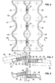
- the concrete crusher consists of a first jaw 1 and a second jaw 2.
- This first jaw 1 and the second jaw 2 are connected to each other via a joint 3 and about an pivot axis 4 formed by the joint 3 from an open one Position, as shown in Fig. 1, in a closed position movable.
- This opening and closing of the concrete crusher takes place in a known manner
- Kind by hydraulic cylinder 5, for example, in Fig. 9 schematically are shown.
- This concrete crusher can in the usual way on one Construction machine attached, can be brought into any position by this be while the hydraulic cylinders 5 over one in this construction machine provided hydraulic unit can be controlled.
- the first jaw 1 of this concrete crusher is through a Frame body 6 formed, which has a free passage on the inside.
- the second jaw 2 is formed by a body 7, which when closing the concrete crushing pliers penetrate into the frame body 6 of the first jaw 1 can.
- the first jaw 1 has first concrete breaking areas that one each attached to the lateral areas 8 of the first jaw 1 rear tooth 9 and a front tooth 10 exist.
- the rear Teeth 9 and the front teeth 10 of the first jaw 1 are open screwed a web 11, which is attached to the outside of the frame body 6 is. This allows the rear teeth 9 and the front teeth 10 from the first jaw 1 removed and replaced or replaced become.
- On the lateral areas 12 of the second jaw 2 also each have a rear tooth 13 and a front tooth 14 attached serve as concrete crushing areas and on a web, not shown, the is attached to the inside of the second jaw by screwing are attached. Centered between the two front teeth 14 of the second Pliers jaw 2, an additional tooth 15 is attached.
- This additional Tooth 15 projects over the two front teeth, which can be reached thereby Effect will be described in detail later. It is also between the rear Teeth 13 of this second jaw 2 an additional tooth 16 attached, which is not visible in FIG. 1, but in particular taken from FIG. 17 can be.
- first cutting elements 17 are used, which consist of a circular arc Block 18 are formed.
- the rear tooth 13 and the front tooth 14 of the second Pliers jaw 2 used first cutting elements 17 of the same type arcuate block 18 are formed.
- On this circular arc Blocks 18 and their attachment in the first jaw 1 and the second Pliers jaw 2 will be discussed in more detail later.
- second cutting elements 20 are attached, which consist of a Plate 21 are formed. Also on these plates 21 will be closer later received.
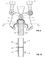
- FIG. 2 in which the second jaw 2 is shown, but the first jaw 1 is designed accordingly the first cutting elements 17 each of a circular arc Block 18.
- This block 18 has a convex surface 22 and can thus in Receiving pockets 23 of the first jaw 1 and the second jaw 2 are used that the convex surface 22 on a corresponding Support surface 24 of the receiving pocket 23 rests. They are kept Blocks 18 in the receiving pockets 23 in each case on the end faces 25 thereof Stop surfaces 26 abut. These stop surfaces 26 are on the one hand through the rear and front teeth 9 and 10 of the first jaw 1 or 14 and 15 of the second jaw 2 formed during the stop surface 26, which lies in the area of the joint 3, on the first jaw 1 or the second jaw 2 is formed.
- the first cutting elements 17 forming blocks 18 in a simple manner in the jaw 1 or 2 inserted and by screwing the rear teeth 9, 13, or front teeth 10, 14 attached to the corresponding jaw 1 or 2 become.
- a replacement of these blocks 18 can thus be carried out very quickly only the rear tooth 9 or 13 has to be removed become.
- the blocks 18 of the first jaw 1 and the second jaw 2 are identical. You can thus freely among each other be replaced. This is a confusion when inserting the Blocks 18 in the jaws 1 and / or 2 excluded, a different Wear and tear can be compensated for by mutual exchange become.
- FIGS. 3-5 The cutting process with these first cutting elements 17, the formed by blocks 18 is shown in FIGS. 3-5.
- the reinforcing iron 27 enters the area of the concave surfaces 28 of the blocks 18, as will be seen later.
- the concave surface 28 and the side surfaces 29 of the blocks 18 each form a cutting edge 30.
- the blocks 18 can thus in the corresponding Pliers jaw 1 or 2 are used that one or the other Cutting edge 30 for cutting the reinforcing iron is in use.
- the concave Surface 28 is equipped with a curvature 31, whereby a wedge angle ⁇ arises, which is greater than 90 °, preferably about 105 °.
- the reinforcing iron 27 lies first on the domes 31 of the cooperating blocks 18, like this 4 can be seen.
- the reinforcing iron 27 is thereby held before the cutting edges 30 begin their cutting process. This will avoid that when the concrete crusher is closed further, the reinforcing iron 27 can be drawn into the cutting gap.
- the on the Block 18 forces are cheaper, the cutting process, as shown in Fig. 5, is done in an optimal manner, since that to be cut Reinforcing iron 27 does not have the tendency to become jammed in the cutting gap which, in turn, would tend to expand. As a result, the cutting edges 30 are optimally stressed, the service life the first cutting elements 17 is extended.
- each block 18 equipped with a guide rib 32 in the area of the convex surface 22, which engages in a groove 33 in the respective receiving pocket of the first Pliers jaw 1 and the second pliers jaw 2 is molded. This will an optimal mounting of the blocks 18 in the corresponding pockets the first jaw 1 and the second jaw 2 received.
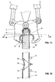
- each of the second Cutting elements 20 each from a plate 21.
- Each against the cutting plane directed surface 34 has a curvature so that each point of this Surface 34 from the pivot axis 4 of the concrete crusher the same distance having.
- the surface 34 which is provided with a curvature, opposite side surfaces 35 form together with this Surface 34 is a cutting edge 36.
- One of the side surfaces 35 is in each case in the state inserted into the jaws 1, 2 by a support surface 37 supported, the receiving pocket in the front area of the concrete crusher forms.
- the plate 21 is located opposite the curved surface 34 Surface on a wall 38 adjacent to the support surface 37 first jaw 1 and the second jaw 2 and is against this screwed.
- these plates 21, which are the second cutting elements 20 form can be exchanged in a simple manner. Since the plates 21 are symmetrical, they can also be rotated so that the one or the other of the cutting edges 36 is in use.
- the side surfaces have 35 indentations 39 and projections 40.
- the reinforcing bars 27 are pushed into the indentations 39, and then clamped by the side surfaces 35 as shown in FIG. 7 is.
- the reinforcement bars 27 are closed the cutting edges 36 are cut, the forces acting on the plates 21 which want to pull the plates together.
- the cutting gap does not widen, but the opposite happens, whereby an optimal cutting effect is achieved.
- the wedge angle the cutting edge is greater than 90 °, preferably about 105 °, which, as mentioned, the cutting edges are protected.
- FIG. 17 it can be seen how the additional tooth 16 in the second jaw 2 is arranged. About halfway between the two rear ones A plate 42 is attached to teeth 13 in the second jaw 2 which the additional tooth 16 is attached. As can already be seen from FIG. 1 is, the additional tooth 15 is attached to this plate 42. The additional tooth 16 is, as can be seen in FIG. 17, on the two rear teeth 13 of the second jaw 2. Also the additional one Tooth 15, as can be seen from FIG. 1, stands over the two front teeth 14 of the second jaw 2. The mode of action of each of these front teeth 14 or above the rear teeth 13 additional Teeth 15 and 16 of the second jaw 2 in connection with the Teeth 9 and 10 of the first jaw 1 will be discussed in more detail below described.
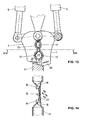
- the concrete crusher is opened with the first jaw 1 and the second jaw 2, for example, via a concrete slab reinforced with reinforcing iron 27 41 brought, as can be seen in Fig. 9.
- the first jaw 1 and the second pliers jaw 2 are then turned over the hydraulic cylinders 5 the joint 3 slowly closed.
- the back teeth 9 of the first jaw 1 come to bear on the concrete slab 41.
- the additional tooth 16, which is centered between the rear teeth 13 of the second jaw 2 is located and is above this, also presses on the concrete slab 41. As can be seen from Fig. 10, this causes a bending effect on the concrete slab generated, the concrete begins to break under the bending forces that occur, as shown schematically in Fig. 10.
- the closing movement of the concrete crushing tongs continues as 13 and 14, the concrete breaking process, which in particular through the rear teeth 9 and 13, through the front teeth 10 and 14 and through the additional teeth 15 and 16 of the first jaw 1 and the second jaw 2 has been almost completed.
- the first cutting elements 17 and the second cutting elements 20 have been little involved in the concrete crushing process and are therefore spared.
- the wedge shape of the teeth now causes the reinforcing iron to the area of the first cutting elements 17 is pressed, as shown in FIG. 13 is shown. When closing the reinforcement iron 27, the are located in the area of the first cutting elements 17.
- the material from which the blocks 18 and the plates 21 are made are made of steel with a hardness of around 58 HRC.
Abstract
Description
Die vorliegende Erfindung bezieht sich auf eine Betonbrechzange
gemäss dem Oberbegriff des Patentanspruches 1.The present invention relates to a concrete crusher
according to the preamble of
Derartige Betonbrechzangen werden eingesetzt zum Abbrechen von aus armiertem Beton bestehenden Bauwerken. Hierbei ist es insbesondere wünschenswert, dass durch die Zangenbewegung der Betonbrechzange einerseits der Beton gebrochen wird und andererseits im gleichen Bewegungsablauf das Armierungseisen geschnitten wird. Dadurch kann das so zerkleinerte Abbruchmaterial ohne zusätzlichen Arbeitsgang, wie beispielsweise Durchtrennen von Armierungseisen mit einem Schneidbrenner, wenn dieses nicht in optimaler Weise durch die Betonbrechzange geschnitten wird, einer Brechmaschine zur Weiterverarbeitung zugeführt werden, in welcher eine Separierung von Beton und Metall erfolgt.Such concrete crushing tongs are used to break off structures made of reinforced concrete. Here it is particular desirable that the pliers move the concrete crusher on the one hand the concrete is broken and on the other hand in the same sequence of movements the reinforcing iron is cut. This means that the demolished material can be shredded without an additional operation, such as cutting of rebars with a cutting torch if this is not in optimal Way is cut by the concrete crusher, a crusher for Further processing can be carried out, in which a separation of concrete and metal is done.
Derartige Betonbrechzangen sind bekannt. So ist beispielsweise in der EP-B-0 770 164 eine derartige Betonbrechzange dargestellt. Diese Betonbrechzange weist zwei Zangenbacken auf, die jeweils mit Betonbrechbereichen und Schneidkanten versehen sind. Die Betonbrechbereiche sind über die Schneidkanten vorstehend, wodurch vermieden werden soll, dass das Brechen des Betons durch die Schneidkanten ausgelöst wird, die zum Schneiden des Armierungseisens vorgesehen sind und deshalb eine relativ scharfe Kante haben sollten. Die Betonbrechkante und die Schneidkante sind umlaufend, d.h., um die Armierungseisen optimal schneiden zu können, darf die Betonbrechkante nicht zu stark über die Schneidkante vorstehend sein. Dadurch lässt sich nicht vermeiden, dass auch die Schneidkante durch das Brechen des Betons stark beansprucht wird, was eine starke Abnützung zur Folge haben kann und sich in nachlassender Schnittqualität für das Armierungseisen ausdrückt.Such concrete crushing tongs are known. For example, in EP-B-0 770 164 shows such a concrete crusher. This concrete crusher has two jaws, each with concrete breaking areas and cutting edges are provided. The concrete crushing areas are over the Cutting edges protruding, which is to avoid breaking of the concrete is triggered by the cutting edges used to cut the Reinforcing iron are provided and therefore have a relatively sharp edge should. The breaking edge and the cutting edge are all-round, i.e. In order to be able to optimally cut the reinforcing bars, the concrete breaking edge may do not protrude too much beyond the cutting edge. This allows do not avoid cutting edge by breaking the concrete is heavily used, which can result in severe wear and tear expresses itself in declining cut quality for the reinforcing iron.
Da die Schneidkanten beim Schneiden des Armierungseisens hohen Zug- und Druckkräften ausgesetzt sind, müssen die entsprechenden Schneidelemente in optimaler Weise mit der entsprechenden Zangenbacke verbunden sein. Bei dieser vorgängig beschriebenen Betonbrechzange wird dies dadurch erreicht, dass das die Schneidkante bildende Material auf die Zangenbacke aufgeschweisst wird. Dies hat aber den Nachteil, dass bei Verschleiss dieser Schneidkante neues Material aufgeschweisst werden muss, was üblicherweise in einer Werkstatt erfolgt, wodurch die Zange einige Zeit nicht in Betrieb ist und somit grosse Totzeiten entstehen. Des weiteren kann nicht beliebig oft weiteres Material auf die Zangenbacke aufgeschweisst werden, da sich durch die Erwärmung Gefügeveränderungen des Materials ergeben, wodurch auch die Festigkeit dieses Materials und somit die Verbindung zwischen aufgeschweisstem Material und Zangenbacke nicht mehr optimal ist und ausbrechen kann.Because the cutting edges are high when cutting the reinforcing iron The corresponding cutting elements must be subjected to tensile and compressive forces optimally connected to the corresponding jaw his. This will be the case with this concrete crusher described above achieved that the material forming the cutting edge on the pliers jaw is welded on. However, this has the disadvantage that when it is worn Cutting edge new material has to be welded on, which is usually the case takes place in a workshop, which means that the pliers are not in operation for some time and thus large dead times arise. Furthermore, more cannot be done indefinitely Material must be welded onto the jaw of the pliers because of the heating Structural changes in the material result, which also Strength of this material and thus the connection between welded Material and pliers jaw is no longer optimal and break out can.
Eine Aufgabe der vorliegenden Erfindung besteht nun darin, eine Betonbrechzange zu schaffen, bei welcher das Erneuern der Schneidkanten ausgeführt werden kann, ohne dass lange Stillstandzeiten dieser Zange entstehen, und bei welcher die oben genannten Nachteile vermieden werden.It is an object of the present invention to provide a To create concrete crushing pliers, in which the renewal of the cutting edges can be carried out without long downtimes of these pliers, and in which the disadvantages mentioned above are avoided.
Erfindungsgemäss erfolgt die Lösung dieser Aufgabe durch die im
Anspruch 1 aufgeführten Merkmale.According to the invention this object is achieved by the
Mit der Möglichkeit, dass die Schneidelemente der Betonbrechzange ausgetauscht werden können, was praktisch am Einsatzort dieser Betonbrechzange vorgenommen werden kann, werden grosse Stillstandzeiten vermieden.With the possibility that the cutting elements of the concrete crusher can be exchanged, which is practical at the place of use of this concrete crusher long downtimes can be avoided.
In vorteilhafter Weise sind erste Schneidelemente, die jeweils aus einem mit einer Biegung versehenen Block gebildet sind, an den seitlichen Bereichen der ersten Zangenbacke und der zweiten Zangenbacke befestigt. Hierbei liegt deren konvexe Fläche in der mit einer entsprechenden Abstützfläche versehenen Aufnahmetasche der Zangenbacken auf, während deren konkave Fläche mit den in einer zur Schwenkachse senkrecht stehenden Ebene liegenden Seitenflächen jeweils eine Schneidkante bilden. Dadurch wird neben dem Vorteil, dass diese einzelnen Blocks sehr schnell ausgewechselt werden können, auch erreicht, dass die Aufnahme der Kräfte beim Schneiden des Armierungseisens und deren Übertragung auf die Zangenbacken in optimaler Weise erfolgen kann. Advantageously, first cutting elements, each of which is made of a are formed with a bend block on the side areas the first jaw and the second jaw. Here lies the convex surface in the provided with a corresponding support surface Pocket of the pliers jaws, while their concave surface with those lying in a plane perpendicular to the swivel axis Side faces each form a cutting edge. In addition to the advantage that these individual blocks can be replaced very quickly, also achieved that the absorption of forces when cutting the reinforcing iron and their transfer to the jaws in an optimal way can be done.
Eine weitere vorteilhafte Ausgestaltung der Erfindung besteht darin, dass an der konvexen Fläche des vorgängig beschriebenen Blocks eine Führungsrippe angebracht ist, die in Längsrichtung zur konvexen Fläche ausgerichtet ist und mittig verläuft, wobei die jeweilige Abstützfläche der Aufnahmetasche mit einer der Führungsrippe entsprechenden Nut ausgestattet ist, in welche die Führungsrippe im eingesetzten Zustand des Blocks in die Zangenbacke eingreift. Mit dieser Einrichtung wird der Block in optimaler Weise in der Aufnahmetasche der jeweiligen Zangenbacke gehalten.Another advantageous embodiment of the invention consists in that a guide rib on the convex surface of the previously described block is attached, which is aligned in the longitudinal direction to the convex surface is and runs in the middle, the respective support surface of the receiving pocket is equipped with a groove corresponding to the guide rib, in which the guide rib in the inserted state of the block in the pliers jaw intervenes. With this device, the block is optimally in the pocket of the respective jaws.
Eine weitere vorteilhafte Ausgestaltung der Erfindung besteht darin, dass an den Endbereichen der Abstützflächen der Aufnahmetaschen Elemente angebracht sind, welche mit Anschlagflächen versehen sind, an welchen die Stirnflächen der Blocks im in die Aufnahmetaschen eingesetzten Zustand anliegend sind. Hierdurch sind diese Blocks optimal in den Aufnahmetaschen gehalten, da die Blocks selbst nicht, beispielsweise mit Schrauben, mit der Zangenbacke verbunden sind, entstehen durch die beim Schneidvorgang auftretenden Kräfte keine übermässigen Spannungsspitzen, die beispielsweise zum Bruch der Schrauben führen könnte, da die Kräfte optimal in die Zangenbacke übergeleitet werden können.Another advantageous embodiment of the invention consists in that elements at the end regions of the support surfaces of the receiving pockets are attached, which are provided with stop surfaces on which the End faces of the blocks are in the inserted state in the receiving pockets are. As a result, these blocks are optimally held in the pockets, since the blocks themselves are not, for example with screws, with the pliers jaw connected, arise from those occurring during the cutting process Forces no excessive voltage peaks, for example, to Breakage of the screws could result, since the forces are optimal in the pliers jaw can be transferred.
In vorteilhafter Weise sind an jedem seitlichen Bereich der Zangenbacken jeweils zwei in Reihe angeordnete, durch die Blocks gebildete erste Schneidelemente vorgesehen, die durch auf die Zangenbacke aufschraubbare Zähne in den Aufnahmetaschen gehalten werden. Die Spitzen der Zähne sind über die Schneidkanten der Schneidelemente vorstehend, wodurch das Brechen des Betons durch diese Zähne mindestens eingeleitet wird und die Schneidkanten somit geschont werden.Advantageously, the jaws on each side area two each arranged in series, formed by the blocks Cutting elements are provided, which can be screwed onto the jaw of the pliers Teeth are kept in the receiving pockets. The tips of the teeth are protruding beyond the cutting edges of the cutting elements, causing breaking of the concrete is at least introduced through these teeth and the Cutting edges are thus protected.
Eine weitere vorteilhafte Ausgestaltung der Erfindung besteht darin, dass die Biegung des die Schneidelemente bildenden Blocks kreisbogenförmig ist, wodurch die Auflagefläche optimal und die Herstellung der Blocks und der Aufnahmetaschen vereinfacht wird. Die zwischen den beiden Schneidkanten liegende konkave Fläche der Blocks weist eine Wölbung auf und der Keilwinkel der Schneidkante wird grösser als 90°. Beim Schneiden des Armierungseisens liegt dieses somit zuerst auf der Wölbung auf, es wird zurechtgedrückt, bevor die Schneidkanten eingreifen, wodurch wiederum die Schneidkanten geschützt werden. Durch die symmetrische Ausgestaltung dieser Blocks kann dieser Block in der Aufnahmetasche so gedreht werden, dass jeweils eine der beiden Schneidkanten im Einsatz ist, wodurch das Material optimal ausgenützt wird.Another advantageous embodiment of the invention consists in that the bend of the block forming the cutting elements is circular is, which makes the contact surface optimal and the production of the blocks and the Recording bags is simplified. The one between the two cutting edges lying concave surface of the blocks has a curvature and the wedge angle the cutting edge becomes larger than 90 °. When cutting the reinforcing iron If this is first on the curvature, it is squeezed before the cutting edges engage, which in turn protects the cutting edges become. Due to the symmetrical design of these blocks, this can Block in the receiving pocket are turned so that one of the two Cutting edges are in use, so that the material is optimally used.
Eine weitere vorteilhafte Ausgestaltung der Erfindung besteht darin, dass am stirnseitigen Bereich der ersten und der zweiten Zangenbacke jeweils eine das zweite Schneidelement bildende Platte angebracht ist, die mit jeweils einer Seitenfläche auf einer entsprechenden Abstützfläche der Aufnahmetasche aufliegt und somit eine optimale Kraftübertragung auf die Zangenbacke erreicht wird.Another advantageous embodiment of the invention consists in that at the front area of the first and the second jaws of each a plate forming the second cutting element is attached, each with a side surface on a corresponding support surface of the receiving pocket rests and thus optimal power transmission to the jaws is achieved becomes.
Diese Platte stützt sich mit ihrer Rückseite an einer an die Abstützfläche angrenzenden Wand der ersten Zangenbacke bzw. der zweiten Zangenbacke ab und ist gegen diese verschraubt. Somit ist auch diese Platte in einfacher Weise austauschbar.The back of this plate is supported on the support surface adjacent wall of the first jaw or the second jaw and is screwed against it. So this plate is also easier Way interchangeable.
In vorteilhafter Weise sind die beiden Seitenfläche der Platte mit Einbuchtungen und Vorsprüngen versehen, entlang welcher die Schneidkante verläuft. Die Platte kann derart in die Aufnahmetasche eingesetzt werden, dass jeweils die eine oder die andere der beiden Schneidkanten im Einsatz ist. Auch hierdurch wird das Material in optimaler Weise ausgenützt.The two side surfaces of the plate are advantageously provided with indentations and protrusions along which the cutting edge runs. The plate can be inserted into the receiving pocket in such a way that one or the other of the two cutting edges is in use. Also in this way the material is optimally used.
Eine weitere vorteilhafte Ausgestaltung der Erfindung besteht darin, dass die Platte zwischen den beiden vorderen Zähnen der ersten bzw. der zweiten Zangenbacke angeordnet ist, wobei die Spitzen der Zähne über die Schneidkante der Platte vorstehend sind. Dadurch wird das Brechen des Betons wiederum über die Zähne mindestens eingeleitet, die Schneidkante der Platte wird hierbei geschont.Another advantageous embodiment of the invention consists in that the plate between the two front teeth of the first and the second pliers jaw is arranged, the tips of the teeth over the Cutting edge of the plate are protruding. This will break the concrete in turn at least initiated via the teeth, the cutting edge of the This protects the plate.
Eine weitere Aufgabe der Erfindung besteht darin, die Betonbrechzange so auszugestalten, dass der Beton in optimaler Weise gebrochen wird und die Schneidkanten der Schneidelemente geschützt werden. Another object of the invention is the concrete crusher to be designed so that the concrete is broken in an optimal way and the cutting edges of the cutting elements are protected.
Dies wird erfindungsgemäss durch die Merkmale des Patentanspruchs
13 gelöst.According to the invention, this is achieved by the features of the
Durch das Anordnen eines zusätzlichen Zahns an der zweiten Zangenbacke, der zwischen jeweils einem Paar bildenden Zähnen angeordnet ist und über deren Spitzen vorsteht, wird erreicht, dass beim Abbrechen von armiertem Beton der durch die Zangen erfasste Bereich zuerst auf Biegung beansprucht wird und der Beton somit leichter bricht.By placing an additional tooth on the second jaw, which is arranged between each pair of teeth and protrudes above their tips, it is achieved that when breaking armored Concrete, the area covered by the pliers is first subjected to bending and the concrete breaks more easily.
In vorteilhafter Weise sind die Zähne in den Zangenbacken so angeordnet, dass beim Schliessen der Zange zuerst die hinteren Zähne auf dem abzubrechenden Betonteil auftreffen und der Beton in diesem Bereich gebrochen wird, und erst danach die vorderen Zähne eingreifen. Dadurch wird das Brechen des Betons einfacher.Advantageously, the teeth in the jaws are arranged that when the pliers are closed, the back teeth on the impact the concrete part to be broken off and the concrete is broken in this area and only then engage the front teeth. This will make it Breaking the concrete easier.
Das Anordnen von zusätzlichen Zähnen zwischen den ein Paar bildenden Zähnen an der zweiten Zangenbacke, wie sie oben beschrieben worden sind, kann auch in Betonbrechzangen eingesetzt werden, die nicht mit den vorgängig beschriebenen auswechselbaren Schneidelementen ausgestattet ist, sondern in jeder Art von Betonbrechzangen, in welchen Betonbrechbereiche und Schneidbereiche zum Schneiden des Armierungseisens vorgesehen sind.Placing additional teeth between the pairing teeth Teeth on the second jaw as described above are, can also be used in concrete crushers that are not compatible with the interchangeable cutting elements described above is equipped, but in every type of concrete crusher, in which concrete crushing areas and cutting areas are provided for cutting the reinforcing iron.
Eine Ausführungsform der vorliegenden Erfindung wird nachfolgend anhand der beiliegenden Zeichnung beispielhaft näher erläutert.An embodiment of the present invention is as follows explained in more detail by way of example with reference to the accompanying drawing.
Es zeigt
Wie in Fig. 1 dargestellt ist, besteht die Betonbrechzange aus einer
ersten Zangenbacke 1 und einer zweiten Zangenbacke 2. Diese erste Zangenbacke
1 und zweite Zangenbacke 2 sind über ein Gelenk 3 miteinander verbunden
und um eine durch das Gelenk 3 gebildete Schwenkachse 4 von einer offenen
Position, wie sie in Fig. 1 dargestellt ist, in eine geschlossene Position
bewegbar. Dieses Öffnen und Schliessen der Betonbrechzange erfolgt in bekannter
Art durch Hydraulikzylinder 5, die beispielsweise in Fig. 9 schematisch
dargestellt sind. Diese Betonbrechzange kann in der üblichen Weise an einer
Baumaschine befestigt werden, kann durch diese in beliebige Positionen gebracht
werden, während die Hydraulikzylinder 5 über ein in dieser Baumaschine
vorgesehenes Hydraulikaggregat ansteuerbar sind.As shown in Fig. 1, the concrete crusher consists of a
Die ersten Zangenbacke 1 dieser Betonbrechzange ist durch einen
Rahmenkörper 6 gebildet, der innenseitig einen freien Durchgang hat. Die
zweite Zangenbacke 2 ist durch einen Körper 7 gebildet, der beim Schliessen
der Betonbrechzange in den Rahmenkörper 6 der ersten Zangenbacke 1 eindringen
kann.The
Die erste Zangenbacke 1 weist erste Betonbrechbereiche auf, die
aus jeweils einem an den seitlichen Bereichen 8 der ersten Zangenbacke 1 angebrachten
hinteren Zahn 9 und einem vorderen Zahn 10 bestehen. Die hinteren
Zähne 9 und die vorderen Zähne 10 der ersten Zangenbacke 1 sind auf
einen Steg 11 geschraubt, der aussenseitig am Rahmenkörper 6 angebracht
ist. Dadurch können die hinteren Zähne 9 und die vorderen Zähne 10 aus der
ersten Zangenbacke 1 herausgenommen und wieder eingesetzt bzw. ausgetauscht
werden. An den seitlichen Bereichen 12 der zweiten Zangenbacke 2 ist
ebenfalls jeweils ein hinterer Zahn 13 und ein vorderer Zahn 14 angebracht, die
als Betonbrechbereiche dienen und die auf einem nicht dargestellten Steg, der
innenseitig an der zweiten Zangenbacke angebracht ist, durch Verschraubung
befestigt sind. Mittig zwischen den beiden vorderen Zähnen 14 der zweiten
Zangenbacke 2 ist ein zusätzlicher Zahn 15 angebracht. Dieser zusätzliche
Zahn 15 steht über die beiden vorderen Zähne vor, die dadurch erreichbare
Wirkung wird später noch genau beschrieben. Ebenfalls ist zwischen den hinteren
Zähnen 13 dieser zweiten Zangenbacke 2 ein zusätzlicher Zahn 16 angebracht,
der in Fig. 1 nicht ersichtlich ist, aber insbesondere der Fig. 17 entnommen
werden kann.The
Jeweils zwischen dem Gelenkbereich und dem hinteren Zahn 9 sowie
zwischen dem hinteren Zahn 9 und dem vorderen Zahn 10 der ersten Zangenbacke
1 sind erste Schneidelemente 17 eingesetzt, die aus einem kreisbogenförmigen
Block 18 gebildet sind. In gleicher Weise sind zwischen dem Gelenkbereich,
dem hinteren Zahn 13 und dem vorderen Zahn 14 der zweiten
Zangenbacke 2 gleichartige erste Schneidelemente 17 eingesetzt, die aus einem
kreisbogenförmigen Block 18 gebildet sind. Auf diese kreisbogenförmigen
Blocks 18 und deren Befestigung in der ersten Zangenbacke 1 und der zweiten
Zangenbacke 2 wird später noch näher eingegangen.Each between the joint area and the
Am stirnseitigen Bereich 19 der ersten Zangenbacke 1 und der
zweiten Zangenbacke 2 sind zweite Schneidelemente 20 befestigt, die aus einer
Platte 21 gebildet sind. Auch auf diese Platten 21 wird später noch näher
eingegangen.At the
Wie aus Fig. 2 ersichtlich ist, in welcher die zweite Zangenbacke 2
dargestellt ist, die erste Zangenbacke 1 aber entsprechend ausgebildet ist, bestehen
die ersten Schneidelemente 17 jeweils aus einem kreisbogenförmigen
Block 18. Dieser Block 18 weist eine konvexe Fläche 22 auf und kann derart in
Aufnahmetaschen 23 der ersten Zangenbacke 1 bzw. der zweiten Zangenbacke
2 eingesetzt werden, dass die konvexe Fläche 22 auf einer entsprechenden
Abstützfläche 24 der Aufnahmetasche 23 aufliegt. Gehalten werden die
Blocks 18 in den Aufnahmetaschen 23 jeweils an deren Stirnflächen 25, die an
Anschlagflächen 26 anliegen. Diese Anschlagflächen 26 werden einerseits
durch die hinteren und vorderen Zähne 9 und 10 der ersten Zangenbacke1
bzw. 14 und 15 der zweiten Zangenbacke 2 gebildet, während die Anschlagfläche
26, die im Bereich des Gelenks 3 liegt, an der ersten Zangenbacke 1 bzw.
der zweiten Zangenbacke 2 angeformt ist.As can be seen from FIG. 2, in which the
In vorteilhafter Weise können zwischen den Stirnflächen 25 der
Blocks 18 und den Anschlagflächen 26 nicht dargestellte Federelemente, beispielsweise
Tellerfedern eingesetzt werden, die in entsprechenden Ausnehmungen
Platz finden könnten. Die Blocks wären damit vorgespannt in den Aufnahmetaschen
23 gehalten, der Sitz zwischen den konvexen Flächen 22 der
Blocks 18 und der Abstützflächen 24 wäre optimal, auch bei einer gegebenenfalls
auftretenden elastischen Verformung der ersten Zangenbacke 1 und/oder
der zweiten Zangenbacke 2, so dass auch keine Verschmutzung des Sitzes
erfolgen könnte.Advantageously, between the end faces 25
Wie aus dieser Figur ersichtlich ist, können die die ersten Schneidelemente
17 bildenden Blocks 18 in einfacher Weise in die Zangenbacke 1 bzw.
2 eingesetzt und durch das Festschrauben der hinteren Zähne 9, 13, bzw. der
vorderen Zähne 10, 14 an der entsprechenden Zangenbacke 1 oder 2 befestigt
werden. Eine Auswechslung dieser Blocks 18 kann somit sehr schnell durchgeführt
werden, hierzu muss sogar nur jeweils der hintere Zahn 9 bzw. 13 herausgenommen
werden. Die Blocks 18 der ersten Zangenbacke 1 und der
zweiten Zangenbacke 2 sind identisch. Sie können somit beliebig untereinander
ausgetauscht werden. Dadurch ist eine Verwechslung beim Einsetzen der
Blocks 18 in die Zangenbacken 1 und/oder 2 ausgeschlossen, eine unterschiedliche
Abnützung kann durch gegenseitiges Austauschen ausgeglichen
werden.As can be seen from this figure, the
Der Schneidvorgang mit diesen ersten Schneidelementen 17, die
durch die Blocks 18 gebildet sind, ist in den Fig. 3 bis 5 dargestellt. Beim
Schliessen der Betonbrechzange gelangt das Armierungseisen 27 in den Bereich
der konkaven Flächen 28 der Blocks 18, wie später noch gesehen wird.
Die konkave Fläche 28 und die Seitenflächen 29 der Blocks 18 bilden jeweils
eine Schneidkante 30. Die Blocks 18 können somit derart in die entsprechende
Zangenbacke 1 bzw. 2 eingesetzt werden, dass die eine oder die andere
Schneidkante 30 zum Schneiden des Armierungseisens im Einsatz ist. Die konkave
Fläche 28 ist mit einer Wölbung 31 ausgestattet, wodurch ein Keilwinkel β
entsteht, der grösser als 90°, vorzugsweise etwa 105°, ist.The cutting process with these
Beim Schliessen der Betonbrechzange liegt das Armierungseisen 27
zuerst auf den Wölbungen 31 der zusammenwirkenden Blocks 18 auf, wie dies
in Fig. 4 ersichtlich ist. Das Armierungseisen 27 wird dadurch festgehalten, bevor
die Schneidkanten 30 ihren Schneidvorgang beginnen. Dadurch wird vermieden,
dass beim weiteren Schliessen der Betonbrechzange das Armierungseisen
27 in den Schnittspalt hineingezogen werden kann. Die auf die
Blocks 18 wirkenden Kräfte werden dadurch günstiger, der Schneidvorgang,
wie er in Fig. 5 dargestellt ist, erfolgt in optimaler Weise, da das zu schneidende
Armierungseisen 27 nicht die Tendenz hat, im Schnittspalt eingeklemmt zu
werden, wodurch dieser seinerseits die Tendenz hätte, aufgeweitet zu werden.
Dadurch werden die Schnittkanten 30 in optimaler Weise beansprucht, die Lebensdauer
der ersten Schneidelemente 17 wird verlängert.When the concrete crushing pliers are closed, the reinforcing
Wie insbesondere aus den Fig. 4 und 5 ersichtlich ist, ist jeder Block
18 im Bereich der konvexen Fläche 22 mit einer Führungsrippe 32 ausgestattet,
welche in eine Nut 33 eingreift, die in der jeweiligen Aufnahmetasche der ersten
Zangenbacke 1 und der zweiten Zangenbacke 2 eingeformt ist. Dadurch wird
eine optimale Halterung der Blocks 18 in den entsprechenden Aufnahmetaschen
der ersten Zangenbacke 1 und der zweiten Zangenbacke 2 erhalten.As can be seen in particular from FIGS. 4 and 5, each
Wie aus den Fig. 6 bis 8 ersichtlich ist, bestehen die zweiten
Schneidelemente 20 jeweils aus einer Platte 21. Die jeweils gegen die Schneidebene
gerichtete Fläche 34 weist eine Wölbung auf, so dass jeder Punkt dieser
Fläche 34 von der Schwenkachse 4 der Betonbrechzange denselben Abstand
aufweist. Die an diese mit einer Wölbung versehenen Fläche 34 anstossenden,
einander gegenüberliegenden Seitenflächen 35 bilden zusammen mit dieser
Fläche 34 jeweils eine Schneidkante 36. Jeweils eine der Seitenflächen 35 ist
im in die Zangenbacken 1, 2 eingesetzten Zustand durch eine Abstützfläche 37
abgestützt, die die Aufnahmetasche im stirnseitigen Bereich der Betonbrechzange
bildet. Die Platte 21 liegt mit ihrer der gewölbten Fläche 34 gegenüberliegenden
Fläche an einer an die Abstützfläche 37 angrenzenden Wand 38 der
ersten Zangenbacke 1 bzw. der zweiten Zangenbacke 2 an und ist gegen diese
verschraubt. Somit können auch diese Platten 21, die die zweiten Schneidelemente
20 bilden, in einfacher Weise ausgetauscht werden. Da die Platten 21
symmetrisch ausgebildet sind, können sie auch so gedreht werden, dass die
eine oder die andere der Schneidkanten 36 im Einsatz ist.As can be seen from FIGS. 6 to 8, there are the second
Wie insbesondere aus Fig. 6 ersichtlich ist, weisen die Seitenflächen
35 Einbuchtungen 39 und Vorsprünge 40 auf. Beim Schliessen der Betonbrechzange
werden die Armierungseisen 27 in die Einbuchtungen 39 geschoben,
und dann durch die Seitenflächen 35 festgeklemmt, wie dies in Fig. 7 ersichtlich
ist. Beim weiteren Schliessen werden die Armierungseisen 27 durch
die Schneidkanten 36 geschnitten, wobei auf die Platten 21 Kräfte wirken, die
die Platten gegeneinanderziehen möchten. Dadurch wird auch bei dieser Anordnung
der Schnittspalt nicht aufgeweitet, sondern das Gegenteil passiert, wodurch
eine optimale Schneidwirkung erreicht wird. Auch hier ist der Keilwinkel
der Schneidkante grösser als 90°, vorzugsweise etwa 105°, wodurch, wie erwähnt,
die Schneidkanten geschützt werden.As can be seen in particular from FIG. 6, the side surfaces have
35
Aus der Fig. 17 ist ersichtlich, wie der zusätzliche Zahn 16 in der
zweiten Zangenbacke 2 angeordnet ist. Etwa mittig zwischen den beiden hinteren
Zähnen 13 ist in der zweiten Zangenbacke 2 eine Platte 42 angebracht, an
welcher der zusätzliche Zahn 16 angebracht ist. Wie bereits aus Fig. 1 ersichtlich
ist, ist auch der zusätzliche Zahn 15 an dieser Platte 42 angebracht. Der
zusätzliche Zahn 16 steht, wie der Fig. 17 entnommen werden kann, über die
beiden hinteren Zähne 13 der zweiten Zangenbacke 2 vor. Auch der zusätzliche
Zahn 15 steht, wie aus der Fig. 1 ersichtlich ist, über die beiden vorderen Zähne
14 der zweiten Zangenbacke 2 vor. Die Wirkungsweise dieser jeweils über die
vorderen Zähne 14 bzw. über die hinteren Zähne 13 vorstehenden zusätzlichen
Zähne 15 bzw. 16 der zweiten Zangenbacke 2 im Zusammenhang mit den
Zähnen 9 und 10 der ersten Zangenbacke 1 wird nachfolgend noch im Detail
beschrieben. From Fig. 17 it can be seen how the
Anhand der Fig. 9 bis 16 wird nachfolgend die Arbeits- und Wirkungsweise
der erfindungsgemässen Betonbrechzange beschrieben. Die Betonbrechzange
wird mit geöffneter ersten Zangenbacke 1 und zweiter Zangenbacke
2 beispielsweise über eine mit Armierungseisen 27 verstärkte Betonplatte
41 gebracht, wie dies in Fig. 9 ersichtlich ist. Die erste Zangenbacke 1
und die zweite Zangenbacke 2 werden dann über die Hydraulikzylinder 5 um
das Gelenk 3 langsam geschlossen. Die hinteren Zähne 9 der ersten Zangenbacke
1 kommen an der Betonplatte 41 zur Anlage. Der zusätzliche Zahn 16,
der sich mittig zwischen den hinteren Zähnen 13 der zweiten Zangenbacke 2
befindet und über diese vorstehend ist, drückt ebenfalls auf die Betonplatte 41.
Wie aus Fig. 10 ersichtlich ist, wird dadurch eine Biegewirkung auf die Betonplatte
erzeugt, der Beton beginnt unter den auftretenden Biegekräften zu brechen,
wie dies in Fig. 10 schematisch dargestellt ist.9 to 16, the mode of operation and operation will be described below
described the concrete crusher according to the invention. The concrete crusher
is opened with the
Die Schliessbewegung der Betonbrechzange wird weitergeführt, wie
dies den Fig. 11 und 12 entnehmbar ist. Der im Bereich der hinteren Zähne 9
und 13 der ersten Zangenbacke 1 und der zweiten Zangenbacke 2 sich befindende
Beton wird weiter gebrochen, die vorderen Zähne 10 der ersten Zangenbacke
werden gegen die Betonplatte 41 gedrückt, der zusätzliche Zahn 15 der
zweiten Zangenbacke 2, der sich zwischen den vorderen Zähnen 14 befindet
und ebenfalls über diese vorstehend ist, bewirkt auch für diesen Bereich der
Betonplatte 41 eine Verbiegung und ein entsprechendes Brechen, wie dies im
Bereich der hinteren Zähne 9 und 13 erfolgt ist. Die ausgebrochenen Betonstücke
werden durch die freie Öffnung der ersten Zangenbacke 1 ausgeworfen.The closing movement of the concrete crushing tongs continues as
11 and 12 can be seen. In the area of the
Die Schliessbewegung der Betonbrechzange wird weitergeführt, wie
dies aus den Fig. 13 und 14 entnommen werden kann, der Betonbrechvorgang,
der insbesondere durch die hinteren Zähne 9 und 13, durch die vorderen Zähne
10 und 14 und durch die zusätzlichen Zähne 15 und 16 der ersten Zangenbacke
1 und der zweiten Zangenbacke 2 ausgeführt wurde, ist nahezu abgeschlossen.
Die ersten Schneidelemente 17 und die zweiten Schneidelemente
20 sind nur wenig in den Betonbrechvorgang involviert worden und werden somit
geschont. Die Keilform der Zähne bewirkt nun, dass das Armierungseisen in
den Bereich der ersten Schneidelemente 17 gedrückt wird, wie dies in Fig. 13
dargestellt ist. Beim Weiterschliessen werden nun die Armierungseisen 27, die
sich im Bereich der ersten Schneidelemente 17 befinden, geschnitten.The closing movement of the concrete crushing tongs continues as
13 and 14, the concrete breaking process,
which in particular through the
Erst wenn diese ersten Schneidelemente 17 das in ihrem Bereich
sich befindende Armierungseisen 27 geschnitten haben, kommen die zweiten
Schneidelemente 20 in den Einsatz und zerschneiden die in diesem Bereich
sich befindenden Armierungseisen, die quer zu denjenigen verlaufen, die durch
die ersten Schneidelemente 17 geschnitten wurden. Dieser Vorgang erfolgt im
letzten Teil der Schliessbewegung der erfindungsgemässen Betonbrechzange.
Die Vorsprünge 40 der miteinander zusammenwirkenden Platten 21 bewirken,
dass das Armierungseisen, das geschnitten werden soll, in die Einbuchtungen
39 gedrückt werden, wo das Schneiden erfolgt. Dieser Zustand ist in den Fig.
15 und 16 dargestellt, das von der Betonbrechzange erfasste Stück der Betonplatte
41 ist sauber herausgebrochen, die längs und quer verlaufenden Armierungseisen
sind herausgeschnitten worden. Die Betonbrechzange kann geöffnet
und an einem anderen Ort der Betonplatte 41 angesetzt werden.Only when these
Das Material, aus welchem die Blocks 18 und die Platten 21 gefertigt
sind, besteht beispielsweise aus einem Stahl mit einer Härte von etwa 58 HRC.The material from which the
Durch die vorgängig beschriebene Anordnung der Zähne und der Schneidelemente in der erfindungsgemässen Betonbrechzange wird zuerst ein stufenweises Herausbrechen des Betons erreicht, danach wird der hintere Teil der Armierungseisen geschnitten, wonach der vordere Teil der Armierungseisen geschnitten wird, und erst dann erfolgt das Durchschneiden der sich im stirnseitigen Bereich der Betonbrechzange befindenden Armierungseisen. Durch dieses stufenweise Vorgehen kann mit der wie üblich aufgebrachten Schliesskraft eine optimale Wirksamkeit der Betonbrechzange erreicht werden, wobei die Schneidkanten zum Schneiden der Armierungseisen geschont werden und somit die Lebensdauer verlängert wird. Durch die Möglichkeit des Auswechselns der Schneidelemente kann die Betonbrechzange, wenn diese Schneidelemente einen zu grossen Verschleiss aufweisen, in kurzer Zeit wieder optimal ausgerüstet werden, wobei dieses Auswechseln praktisch am Einsatzort dieser Betonbrechzange erfolgen kann.Due to the arrangement of the teeth and the previously described Cutting elements in the concrete crusher according to the invention is first a gradual breaking out of the concrete is achieved, then the rear part cut the reinforcing iron, after which the front part of the reinforcing iron is cut, and only then is the cut in the front Reinforcing iron located in the area of the concrete crushing tongs. Because of this step-by-step procedure with the closing force applied as usual optimal effectiveness of the concrete crushing tongs can be achieved, the Cutting edges for cutting the reinforcing bars are protected and thus the lifespan is extended. Through the possibility of changing The cutting elements can use the concrete crusher if these cutting elements show too much wear, optimally equipped again in a short time be, this replacement practically at the place of use of this concrete crusher can be done.
Claims (15)
Priority Applications (6)
| Application Number | Priority Date | Filing Date | Title |
|---|---|---|---|
| EP99811219A EP1113111B1 (en) | 1999-12-30 | 1999-12-30 | Concrete breaking shear |
| DE59904659T DE59904659D1 (en) | 1999-12-30 | 1999-12-30 | Concrete-crushing pincers |
| AT99811219T ATE234970T1 (en) | 1999-12-30 | 1999-12-30 | CONCRETE BRUSHING PLIERS |
| PCT/CH2000/000686 WO2001049945A1 (en) | 1999-12-30 | 2000-12-22 | Concrete crushing grappler |
| AU19806/01A AU1980601A (en) | 1999-12-30 | 2000-12-22 | Concrete crushing grappler |
| US10/169,388 US6766973B2 (en) | 1999-12-30 | 2000-12-22 | Concrete crushing grappler |
Applications Claiming Priority (1)
| Application Number | Priority Date | Filing Date | Title |
|---|---|---|---|
| EP99811219A EP1113111B1 (en) | 1999-12-30 | 1999-12-30 | Concrete breaking shear |
Publications (2)
| Publication Number | Publication Date |
|---|---|
| EP1113111A1 true EP1113111A1 (en) | 2001-07-04 |
| EP1113111B1 EP1113111B1 (en) | 2003-03-19 |
Family
ID=8243224
Family Applications (1)
| Application Number | Title | Priority Date | Filing Date |
|---|---|---|---|
| EP99811219A Expired - Lifetime EP1113111B1 (en) | 1999-12-30 | 1999-12-30 | Concrete breaking shear |
Country Status (6)
| Country | Link |
|---|---|
| US (1) | US6766973B2 (en) |
| EP (1) | EP1113111B1 (en) |
| AT (1) | ATE234970T1 (en) |
| AU (1) | AU1980601A (en) |
| DE (1) | DE59904659D1 (en) |
| WO (1) | WO2001049945A1 (en) |
Cited By (5)
| Publication number | Priority date | Publication date | Assignee | Title |
|---|---|---|---|---|
| WO2007106919A1 (en) | 2006-03-23 | 2007-09-27 | Alois Wimmer | Demolition tool |
| DE102010015416A1 (en) | 2010-04-19 | 2011-10-20 | Lst Swiss Ag | Hydraulically-operated plier e.g. concrete breaking plier, for cutting e.g. reinforcing irons, has cutting edges attached to lateral regions of plier jaws, where interrupted section of one of edges is formed from cutting elements |
| EP2672019A1 (en) * | 2012-06-07 | 2013-12-11 | Caterpillar Work Tools B. V. | A jaw assembly for a demolition tool |
| US9333570B2 (en) | 2006-09-27 | 2016-05-10 | Caterpillar Inc. | Reversible bolt-on piercing tip |
| US10316530B2 (en) | 2012-06-07 | 2019-06-11 | Caterpillar Work Tools B.V. | Jaw assembly for a demolition tool |
Families Citing this family (20)
| Publication number | Priority date | Publication date | Assignee | Title |
|---|---|---|---|---|
| US7726594B2 (en) * | 2001-10-03 | 2010-06-01 | Leward Nile Smith | Multi-functional tool assembly for processing tool of material processing machine |
| DE102004028011A1 (en) * | 2004-06-08 | 2005-12-29 | Atlas Copco Construction Tools Gmbh | Demolition implement for attachment to a boom |
| NL1028334C2 (en) * | 2005-02-18 | 2006-08-21 | Holmatro Ind Equip | Hinge bolt construction with lock. |
| US20070107917A1 (en) * | 2005-11-14 | 2007-05-17 | Doherty Brian J | Multifunctional robot tool |
| US20070145171A1 (en) * | 2005-12-23 | 2007-06-28 | The Stanley Works | Rebar cutting shears |
| US8176808B2 (en) * | 2007-09-13 | 2012-05-15 | Foster-Miller, Inc. | Robot arm assembly |
| US8414043B2 (en) | 2008-10-21 | 2013-04-09 | Foster-Miller, Inc. | End effector for mobile remotely controlled robot |
| US8322249B2 (en) | 2008-12-18 | 2012-12-04 | Foster-Miller, Inc. | Robot arm assembly |
| US8141924B2 (en) * | 2008-12-29 | 2012-03-27 | Foster-Miller, Inc. | Gripper system |
| US8628035B2 (en) | 2009-08-07 | 2014-01-14 | John R. Ramun | Blade set for jaws used in rail breaking demolition equipment |
| US8231071B2 (en) * | 2009-08-07 | 2012-07-31 | John R. Ramun | Blade set for jaws used in rail breaking demolition equipment |
| US20110225829A1 (en) * | 2010-03-22 | 2011-09-22 | Genesis Attachments, Llc | Heavy duty configurable shear crusher demolition tool |
| US8727252B1 (en) | 2011-08-23 | 2014-05-20 | Jeffrey Sterling Phipps | Rock crusher system for an excavator |
| US8646709B2 (en) * | 2012-04-11 | 2014-02-11 | John R. Ramun | Jaw set with serrated cutting blades |
| USD752114S1 (en) * | 2012-06-04 | 2016-03-22 | Caterpillar Work Tools B.V. | Multi-processor and modular wear protection system |
| USD748694S1 (en) * | 2015-03-19 | 2016-02-02 | Buckhurst Group Limited | Pipe-crushing apparatus |
| US10668475B2 (en) | 2016-01-31 | 2020-06-02 | Genesis Attachments, Llc | Pulverizer attachment with tooth rails |
| US10967380B2 (en) | 2017-03-31 | 2021-04-06 | Stanley Black & Decker, Inc. | Heavy duty material processor |
| CN110465395B (en) * | 2019-08-28 | 2020-12-29 | 安徽景鸿茶油有限公司 | Camellia oil residue crusher |
| CN112452400B (en) * | 2020-11-22 | 2022-04-29 | 金伟兵 | Stone refining and rolling device |
Citations (8)
| Publication number | Priority date | Publication date | Assignee | Title |
|---|---|---|---|---|
| US4838493A (en) * | 1988-06-10 | 1989-06-13 | Labounty Kenneth R | Concrete crusher |
| US5183216A (en) * | 1990-04-25 | 1993-02-02 | Helmut Wack | Demolishing apparatus |
| US5301882A (en) * | 1991-08-27 | 1994-04-12 | Ohyodo Diesel Co., Ltd. | Concrete crusher |
| EP0666131A1 (en) * | 1994-02-03 | 1995-08-09 | Helmut Wack | Metal demolition shear |
| US5474242A (en) * | 1994-10-11 | 1995-12-12 | The Stanley Works | Demolition tools with jaws having replaceable working surfaces |
| EP0755742A1 (en) * | 1995-07-26 | 1997-01-29 | OHYODO DIESEL CO., Ltd. | Double-scissors cutter |
| US5822893A (en) * | 1994-07-13 | 1998-10-20 | Schilling-Ostermeyer Maschinenbau Gmbh | Concrete crushing tongs |
| US5992023A (en) * | 1998-07-31 | 1999-11-30 | The Stanley Works | Shear with interchangeable wear parts |
Family Cites Families (5)
| Publication number | Priority date | Publication date | Assignee | Title |
|---|---|---|---|---|
| FR2632999A1 (en) * | 1988-06-15 | 1989-12-22 | Zepf Hans Rudolf | RIPTURE PLIERS FOR DEMOLISHING MASONRY WORKS, IN PARTICULAR ARMED CONCRETE WALLS |
| FR2637303B1 (en) * | 1988-09-30 | 1990-12-14 | Ameca Sa | CONCRETE BREAKERS |
| JPH0657970A (en) * | 1992-08-10 | 1994-03-01 | Ooyodo Diesel Kk | Concrete crusher |
| JP2585939B2 (en) * | 1993-01-26 | 1997-02-26 | 大淀小松株式会社 | Crushing equipment |
| US5926958A (en) * | 1997-10-03 | 1999-07-27 | Allied Gator, Inc. | Metal cutting shear and piercing tip therefor |
-
1999
- 1999-12-30 AT AT99811219T patent/ATE234970T1/en active
- 1999-12-30 DE DE59904659T patent/DE59904659D1/en not_active Expired - Lifetime
- 1999-12-30 EP EP99811219A patent/EP1113111B1/en not_active Expired - Lifetime
-
2000
- 2000-12-22 WO PCT/CH2000/000686 patent/WO2001049945A1/en active Application Filing
- 2000-12-22 AU AU19806/01A patent/AU1980601A/en not_active Abandoned
- 2000-12-22 US US10/169,388 patent/US6766973B2/en not_active Expired - Fee Related
Patent Citations (9)
| Publication number | Priority date | Publication date | Assignee | Title |
|---|---|---|---|---|
| US4838493A (en) * | 1988-06-10 | 1989-06-13 | Labounty Kenneth R | Concrete crusher |
| US4838493B1 (en) * | 1988-06-10 | 1994-12-06 | Labounty Manufacturing | Concrete crusher |
| US5183216A (en) * | 1990-04-25 | 1993-02-02 | Helmut Wack | Demolishing apparatus |
| US5301882A (en) * | 1991-08-27 | 1994-04-12 | Ohyodo Diesel Co., Ltd. | Concrete crusher |
| EP0666131A1 (en) * | 1994-02-03 | 1995-08-09 | Helmut Wack | Metal demolition shear |
| US5822893A (en) * | 1994-07-13 | 1998-10-20 | Schilling-Ostermeyer Maschinenbau Gmbh | Concrete crushing tongs |
| US5474242A (en) * | 1994-10-11 | 1995-12-12 | The Stanley Works | Demolition tools with jaws having replaceable working surfaces |
| EP0755742A1 (en) * | 1995-07-26 | 1997-01-29 | OHYODO DIESEL CO., Ltd. | Double-scissors cutter |
| US5992023A (en) * | 1998-07-31 | 1999-11-30 | The Stanley Works | Shear with interchangeable wear parts |
Cited By (11)
| Publication number | Priority date | Publication date | Assignee | Title |
|---|---|---|---|---|
| WO2007106919A1 (en) | 2006-03-23 | 2007-09-27 | Alois Wimmer | Demolition tool |
| US9333570B2 (en) | 2006-09-27 | 2016-05-10 | Caterpillar Inc. | Reversible bolt-on piercing tip |
| DE102010015416A1 (en) | 2010-04-19 | 2011-10-20 | Lst Swiss Ag | Hydraulically-operated plier e.g. concrete breaking plier, for cutting e.g. reinforcing irons, has cutting edges attached to lateral regions of plier jaws, where interrupted section of one of edges is formed from cutting elements |
| EP2672019A1 (en) * | 2012-06-07 | 2013-12-11 | Caterpillar Work Tools B. V. | A jaw assembly for a demolition tool |
| WO2013182626A1 (en) * | 2012-06-07 | 2013-12-12 | Caterpillar Work Tools B.V. | A jaw assembly for a demolition tool |
| EP2801669A1 (en) * | 2012-06-07 | 2014-11-12 | Caterpillar Work Tools B. V. | A jaw assembly for a demolition tool |
| CN104350209A (en) * | 2012-06-07 | 2015-02-11 | 卡特彼勒作业机具有限公司 | A jaw assembly for a demolition tool |
| EP2944729A3 (en) * | 2012-06-07 | 2015-12-30 | Caterpillar Work Tools B. V. | A jaw assembly for a demolition tool |
| CN104350209B (en) * | 2012-06-07 | 2016-08-17 | 卡特彼勒作业机具有限公司 | Jaw assembly for removal tool |
| US10316530B2 (en) | 2012-06-07 | 2019-06-11 | Caterpillar Work Tools B.V. | Jaw assembly for a demolition tool |
| US10392776B2 (en) | 2012-06-07 | 2019-08-27 | Caterpillar Work Tools B.V. | Jaw assembly for a demolition tool |
Also Published As
| Publication number | Publication date |
|---|---|
| AU1980601A (en) | 2001-07-16 |
| US20030132327A1 (en) | 2003-07-17 |
| DE59904659D1 (en) | 2003-04-24 |
| WO2001049945A1 (en) | 2001-07-12 |
| ATE234970T1 (en) | 2003-04-15 |
| EP1113111B1 (en) | 2003-03-19 |
| US6766973B2 (en) | 2004-07-27 |
Similar Documents
| Publication | Publication Date | Title |
|---|---|---|
| EP1113111B1 (en) | Concrete breaking shear | |
| EP0453773B1 (en) | Wrecking device | |
| EP1749939B1 (en) | Adapter for work tool as part of quick change coupling and quick change coupling | |
| DE202006009273U1 (en) | Cutting jaw pair | |
| EP0347371B1 (en) | Crushing tongs for demolishing building structures, especially reinforced-concrete walls | |
| DE4114187A1 (en) | SCISSORS WITH INTERCHANGEABLE BLADES | |
| DE19818482C1 (en) | Hand crimping pliers for crimping ferrules | |
| EP2001627B1 (en) | Demolition tool | |
| EP2403998B1 (en) | Attachment for construction equipment | |
| DE1577246C3 (en) | Safety device for work machines | |
| EP0221340A1 (en) | Holding device for gate cutters | |
| AT392740B (en) | BOW BAR FOR IMPACT CRUSHERS OD. DGL. CRUSHING MACHINES | |
| DE2032444A1 (en) | tongs | |
| EP0529380B1 (en) | Breaking tool | |
| DE10243308A1 (en) | Device for reducing friction forces produced on the action of a comminuting material on scrap shears comprises a jaw arm having a wedge element forming a working surface facing the counter surface of an adjacent jaw arm | |
| DE602005001516T2 (en) | Cutting device for cutting metals, especially for cutting metal profiles | |
| DE2938208A1 (en) | DEVICE FOR COUPLING A TOOL TO THE EXTENSION OF A EXCAVATOR | |
| EP0089499A1 (en) | Cutter tool for a cutting chain or a cutting belt | |
| DE2809229C2 (en) | Scissors for cutting through the parallel longitudinal elements of grids or gratings | |
| EP3612308A1 (en) | Crusher assembly for a jaw crusher | |
| DE3722710A1 (en) | Crusher or similar comminution device | |
| EP2617494A1 (en) | Tool for a reduction device | |
| DD280350A1 (en) | CONCRETE BREAKER | |
| DE102010015416A1 (en) | Hydraulically-operated plier e.g. concrete breaking plier, for cutting e.g. reinforcing irons, has cutting edges attached to lateral regions of plier jaws, where interrupted section of one of edges is formed from cutting elements | |
| DE4002641A1 (en) | Pivoting jaw crusher - has jaw support supported by bell crank lever held between hydraulic brake plates |
Legal Events
| Date | Code | Title | Description |
|---|---|---|---|
| PUAI | Public reference made under article 153(3) epc to a published international application that has entered the european phase |
Free format text: ORIGINAL CODE: 0009012 |
|
| AK | Designated contracting states |
Kind code of ref document: A1 Designated state(s): AT BE CH CY DE DK ES FI FR GB GR IE IT LI LU MC NL PT SE |
|
| AX | Request for extension of the european patent |
Free format text: AL;LT;LV;MK;RO;SI |
|
| 17P | Request for examination filed |
Effective date: 20011123 |
|
| 17Q | First examination report despatched |
Effective date: 20020125 |
|
| AKX | Designation fees paid |
Free format text: AT BE CH CY DE DK ES FI FR GB GR IE IT LI LU MC NL PT SE |
|
| GRAG | Despatch of communication of intention to grant |
Free format text: ORIGINAL CODE: EPIDOS AGRA |
|
| GRAG | Despatch of communication of intention to grant |
Free format text: ORIGINAL CODE: EPIDOS AGRA |
|
| GRAH | Despatch of communication of intention to grant a patent |
Free format text: ORIGINAL CODE: EPIDOS IGRA |
|
| GRAH | Despatch of communication of intention to grant a patent |
Free format text: ORIGINAL CODE: EPIDOS IGRA |
|
| GRAA | (expected) grant |
Free format text: ORIGINAL CODE: 0009210 |
|
| AK | Designated contracting states |
Designated state(s): AT BE CH CY DE DK ES FI FR GB GR IE IT LI LU MC NL PT SE |
|
| PG25 | Lapsed in a contracting state [announced via postgrant information from national office to epo] |
Ref country code: IE Free format text: LAPSE BECAUSE OF FAILURE TO SUBMIT A TRANSLATION OF THE DESCRIPTION OR TO PAY THE FEE WITHIN THE PRESCRIBED TIME-LIMIT Effective date: 20030319 Ref country code: GR Free format text: LAPSE BECAUSE OF FAILURE TO SUBMIT A TRANSLATION OF THE DESCRIPTION OR TO PAY THE FEE WITHIN THE PRESCRIBED TIME-LIMIT Effective date: 20030319 Ref country code: GB Free format text: LAPSE BECAUSE OF FAILURE TO SUBMIT A TRANSLATION OF THE DESCRIPTION OR TO PAY THE FEE WITHIN THE PRESCRIBED TIME-LIMIT Effective date: 20030319 Ref country code: FI Free format text: LAPSE BECAUSE OF FAILURE TO SUBMIT A TRANSLATION OF THE DESCRIPTION OR TO PAY THE FEE WITHIN THE PRESCRIBED TIME-LIMIT Effective date: 20030319 |
|
| REG | Reference to a national code |
Ref country code: GB Ref legal event code: FG4D Free format text: NOT ENGLISH |
|
| REG | Reference to a national code |
Ref country code: CH Ref legal event code: NV Representative=s name: BOVARD AG PATENTANWAELTE Ref country code: CH Ref legal event code: EP |
|
| REF | Corresponds to: |
Ref document number: 59904659 Country of ref document: DE Date of ref document: 20030424 Kind code of ref document: P |
|
| PG25 | Lapsed in a contracting state [announced via postgrant information from national office to epo] |
Ref country code: SE Free format text: LAPSE BECAUSE OF FAILURE TO SUBMIT A TRANSLATION OF THE DESCRIPTION OR TO PAY THE FEE WITHIN THE PRESCRIBED TIME-LIMIT Effective date: 20030619 Ref country code: DK Free format text: LAPSE BECAUSE OF FAILURE TO SUBMIT A TRANSLATION OF THE DESCRIPTION OR TO PAY THE FEE WITHIN THE PRESCRIBED TIME-LIMIT Effective date: 20030619 |
|
| PG25 | Lapsed in a contracting state [announced via postgrant information from national office to epo] |
Ref country code: PT Free format text: LAPSE BECAUSE OF FAILURE TO SUBMIT A TRANSLATION OF THE DESCRIPTION OR TO PAY THE FEE WITHIN THE PRESCRIBED TIME-LIMIT Effective date: 20030620 |
|
| GBV | Gb: ep patent (uk) treated as always having been void in accordance with gb section 77(7)/1977 [no translation filed] |
Effective date: 20030319 |
|
| PG25 | Lapsed in a contracting state [announced via postgrant information from national office to epo] |
Ref country code: ES Free format text: LAPSE BECAUSE OF FAILURE TO SUBMIT A TRANSLATION OF THE DESCRIPTION OR TO PAY THE FEE WITHIN THE PRESCRIBED TIME-LIMIT Effective date: 20030930 |
|
| ET | Fr: translation filed | ||
| REG | Reference to a national code |
Ref country code: IE Ref legal event code: FD4D Ref document number: 1113111E Country of ref document: IE |
|
| PG25 | Lapsed in a contracting state [announced via postgrant information from national office to epo] |
Ref country code: LU Free format text: LAPSE BECAUSE OF NON-PAYMENT OF DUE FEES Effective date: 20031230 Ref country code: CY Free format text: LAPSE BECAUSE OF FAILURE TO SUBMIT A TRANSLATION OF THE DESCRIPTION OR TO PAY THE FEE WITHIN THE PRESCRIBED TIME-LIMIT Effective date: 20031230 |
|
| PG25 | Lapsed in a contracting state [announced via postgrant information from national office to epo] |
Ref country code: MC Free format text: LAPSE BECAUSE OF NON-PAYMENT OF DUE FEES Effective date: 20031231 |
|
| PLBE | No opposition filed within time limit |
Free format text: ORIGINAL CODE: 0009261 |
|
| STAA | Information on the status of an ep patent application or granted ep patent |
Free format text: STATUS: NO OPPOSITION FILED WITHIN TIME LIMIT |
|
| 26N | No opposition filed |
Effective date: 20031222 |
|
| REG | Reference to a national code |
Ref country code: CH Ref legal event code: PFA Owner name: MURI, FRANZ Free format text: MURI, FRANZ#SCHUTZ 35#6022 GROSSWANGEN (CH) -TRANSFER TO- MURI, FRANZ#SCHUTZ 35#6022 GROSSWANGEN (CH) |
|
| PGFP | Annual fee paid to national office [announced via postgrant information from national office to epo] |
Ref country code: FR Payment date: 20110120 Year of fee payment: 12 |
|
| PGFP | Annual fee paid to national office [announced via postgrant information from national office to epo] |
Ref country code: BE Payment date: 20110104 Year of fee payment: 12 |
|
| BERE | Be: lapsed |
Owner name: *MURI FRANZ Effective date: 20111231 |
|
| REG | Reference to a national code |
Ref country code: FR Ref legal event code: ST Effective date: 20120831 |
|
| PG25 | Lapsed in a contracting state [announced via postgrant information from national office to epo] |
Ref country code: BE Free format text: LAPSE BECAUSE OF NON-PAYMENT OF DUE FEES Effective date: 20111231 |
|
| PG25 | Lapsed in a contracting state [announced via postgrant information from national office to epo] |
Ref country code: FR Free format text: LAPSE BECAUSE OF NON-PAYMENT OF DUE FEES Effective date: 20120102 |
|
| PGFP | Annual fee paid to national office [announced via postgrant information from national office to epo] |
Ref country code: CH Payment date: 20140325 Year of fee payment: 15 Ref country code: NL Payment date: 20140328 Year of fee payment: 15 Ref country code: DE Payment date: 20140328 Year of fee payment: 15 |
|
| PGFP | Annual fee paid to national office [announced via postgrant information from national office to epo] |
Ref country code: AT Payment date: 20140411 Year of fee payment: 15 Ref country code: IT Payment date: 20140331 Year of fee payment: 15 |
|
| REG | Reference to a national code |
Ref country code: DE Ref legal event code: R119 Ref document number: 59904659 Country of ref document: DE |
|
| REG | Reference to a national code |
Ref country code: NL Ref legal event code: V1 Effective date: 20150701 |
|
| REG | Reference to a national code |
Ref country code: NL Ref legal event code: V1 Effective date: 20150701 |
|
| REG | Reference to a national code |
Ref country code: CH Ref legal event code: PL |
|
| REG | Reference to a national code |
Ref country code: AT Ref legal event code: MM01 Ref document number: 234970 Country of ref document: AT Kind code of ref document: T Effective date: 20141230 |
|
| PG25 | Lapsed in a contracting state [announced via postgrant information from national office to epo] |
Ref country code: NL Free format text: LAPSE BECAUSE OF NON-PAYMENT OF DUE FEES Effective date: 20150701 |
|
| PG25 | Lapsed in a contracting state [announced via postgrant information from national office to epo] |
Ref country code: CH Free format text: LAPSE BECAUSE OF NON-PAYMENT OF DUE FEES Effective date: 20141231 Ref country code: DE Free format text: LAPSE BECAUSE OF NON-PAYMENT OF DUE FEES Effective date: 20150701 Ref country code: LI Free format text: LAPSE BECAUSE OF NON-PAYMENT OF DUE FEES Effective date: 20141231 |
|
| PG25 | Lapsed in a contracting state [announced via postgrant information from national office to epo] |
Ref country code: AT Free format text: LAPSE BECAUSE OF NON-PAYMENT OF DUE FEES Effective date: 20141230 |
|
| PG25 | Lapsed in a contracting state [announced via postgrant information from national office to epo] |
Ref country code: IT Free format text: LAPSE BECAUSE OF NON-PAYMENT OF DUE FEES Effective date: 20141230 |