EP1113103A2 - Door lock switch assembly in drum type washing machine - Google Patents
Door lock switch assembly in drum type washing machine Download PDFInfo
- Publication number
- EP1113103A2 EP1113103A2 EP00204759A EP00204759A EP1113103A2 EP 1113103 A2 EP1113103 A2 EP 1113103A2 EP 00204759 A EP00204759 A EP 00204759A EP 00204759 A EP00204759 A EP 00204759A EP 1113103 A2 EP1113103 A2 EP 1113103A2
- Authority
- EP
- European Patent Office
- Prior art keywords
- slide
- door lock
- door
- movable contact
- latch holder
- Prior art date
- Legal status (The legal status is an assumption and is not a legal conclusion. Google has not performed a legal analysis and makes no representation as to the accuracy of the status listed.)
- Granted
Links
- 238000005406 washing Methods 0.000 title claims abstract description 29
- 230000009471 action Effects 0.000 claims abstract description 11
- 230000006835 compression Effects 0.000 claims description 11
- 238000007906 compression Methods 0.000 claims description 11
- 230000005540 biological transmission Effects 0.000 claims description 2
- XLYOFNOQVPJJNP-UHFFFAOYSA-N water Substances O XLYOFNOQVPJJNP-UHFFFAOYSA-N 0.000 description 13
- 238000003825 pressing Methods 0.000 description 4
- 238000010276 construction Methods 0.000 description 2
- 239000003599 detergent Substances 0.000 description 2
- 238000000034 method Methods 0.000 description 2
- 238000012986 modification Methods 0.000 description 2
- 230000004048 modification Effects 0.000 description 2
- 230000008569 process Effects 0.000 description 2
- 238000010009 beating Methods 0.000 description 1
- 230000000903 blocking effect Effects 0.000 description 1
- 238000005520 cutting process Methods 0.000 description 1
- 230000002542 deteriorative effect Effects 0.000 description 1
- 230000000694 effects Effects 0.000 description 1
- 230000006872 improvement Effects 0.000 description 1
- 239000011810 insulating material Substances 0.000 description 1
- 238000004519 manufacturing process Methods 0.000 description 1
- 239000000463 material Substances 0.000 description 1
- 230000002035 prolonged effect Effects 0.000 description 1
- 230000000630 rising effect Effects 0.000 description 1
- 238000007493 shaping process Methods 0.000 description 1
- 238000003860 storage Methods 0.000 description 1
Images










Classifications
-
- D—TEXTILES; PAPER
- D06—TREATMENT OF TEXTILES OR THE LIKE; LAUNDERING; FLEXIBLE MATERIALS NOT OTHERWISE PROVIDED FOR
- D06F—LAUNDERING, DRYING, IRONING, PRESSING OR FOLDING TEXTILE ARTICLES
- D06F37/00—Details specific to washing machines covered by groups D06F21/00 - D06F25/00
- D06F37/42—Safety arrangements, e.g. for stopping rotation of the receptacle upon opening of the casing door
-
- Y—GENERAL TAGGING OF NEW TECHNOLOGICAL DEVELOPMENTS; GENERAL TAGGING OF CROSS-SECTIONAL TECHNOLOGIES SPANNING OVER SEVERAL SECTIONS OF THE IPC; TECHNICAL SUBJECTS COVERED BY FORMER USPC CROSS-REFERENCE ART COLLECTIONS [XRACs] AND DIGESTS
- Y10—TECHNICAL SUBJECTS COVERED BY FORMER USPC
- Y10T—TECHNICAL SUBJECTS COVERED BY FORMER US CLASSIFICATION
- Y10T292/00—Closure fasteners
- Y10T292/08—Bolts
- Y10T292/096—Sliding
- Y10T292/1014—Operating means
- Y10T292/1021—Motor
-
- Y—GENERAL TAGGING OF NEW TECHNOLOGICAL DEVELOPMENTS; GENERAL TAGGING OF CROSS-SECTIONAL TECHNOLOGIES SPANNING OVER SEVERAL SECTIONS OF THE IPC; TECHNICAL SUBJECTS COVERED BY FORMER USPC CROSS-REFERENCE ART COLLECTIONS [XRACs] AND DIGESTS
- Y10—TECHNICAL SUBJECTS COVERED BY FORMER USPC
- Y10T—TECHNICAL SUBJECTS COVERED BY FORMER US CLASSIFICATION
- Y10T292/00—Closure fasteners
- Y10T292/08—Bolts
- Y10T292/1043—Swinging
- Y10T292/1062—Spring retracted
-
- Y—GENERAL TAGGING OF NEW TECHNOLOGICAL DEVELOPMENTS; GENERAL TAGGING OF CROSS-SECTIONAL TECHNOLOGIES SPANNING OVER SEVERAL SECTIONS OF THE IPC; TECHNICAL SUBJECTS COVERED BY FORMER USPC CROSS-REFERENCE ART COLLECTIONS [XRACs] AND DIGESTS
- Y10—TECHNICAL SUBJECTS COVERED BY FORMER USPC
- Y10T—TECHNICAL SUBJECTS COVERED BY FORMER US CLASSIFICATION
- Y10T70/00—Locks
- Y10T70/70—Operating mechanism
- Y10T70/7051—Using a powered device [e.g., motor]
- Y10T70/7062—Electrical type [e.g., solenoid]
-
- Y—GENERAL TAGGING OF NEW TECHNOLOGICAL DEVELOPMENTS; GENERAL TAGGING OF CROSS-SECTIONAL TECHNOLOGIES SPANNING OVER SEVERAL SECTIONS OF THE IPC; TECHNICAL SUBJECTS COVERED BY FORMER USPC CROSS-REFERENCE ART COLLECTIONS [XRACs] AND DIGESTS
- Y10—TECHNICAL SUBJECTS COVERED BY FORMER USPC
- Y10T—TECHNICAL SUBJECTS COVERED BY FORMER US CLASSIFICATION
- Y10T70/00—Locks
- Y10T70/70—Operating mechanism
- Y10T70/7051—Using a powered device [e.g., motor]
- Y10T70/7062—Electrical type [e.g., solenoid]
- Y10T70/7102—And details of blocking system [e.g., linkage, latch, pawl, spring]
Definitions
- the present invention relates to a door lock switch assembly in a drum type washing machine, and more particularly, to a door lock switch assembly which has a simple structure and an improved operation reliability in locking and unlocking a door.
- the drum type washing machine washes laundry by using friction between a drum rotated by a driving force from a motor and laundry under a state detergent, washing water, and the laundry are introduced in the drum.
- the drum type washing machine has advantages in that the laundry is almost not involved in damage and tangling between the laundry, and in that washing effects obtainable by beating and rubbing the laundry can be provided.
- FIG. 1 illustrates an outside view of a related art drum type washing machine.
- a tub a water storage tank, is provided inside of a body 13, and a drum 14 is fixed at a center of the tub to be rotated by the driving motor.
- the drum type washing machine has a door at the front of the body 13, for introducing and taking out the laundry. And, since the detergent, washing water and laundry will gush out of the door 15 to make a floor dirty if the door 15 is opened in the middle of washing unintentionally, the related art drum type washing machine has a door lock for preventing the unintentional opening of the door 15 before it happens.
- the door lock has a door lock switch assembly on an inside of a front side of the body 13, and a latch 16 at a front end of an opposite side of a hinge of the door 15.
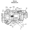
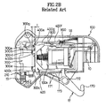
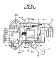
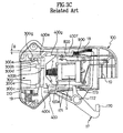
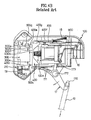
- the related art door lock switch. assembly is provided with a switch case 100, a switch cover 200 fitted to the switch case 100, a latch holder 300, a slide 400, a solenoid assembly, a switching terminal, and an operating lever 17.
- the latch holder 300 is rotatably fitted to the front of the switch case 100 to exert a restoring force in door unlocking direction, wherein a left side on the drawing is referred to the front and a right side thereon is referred to the rear in Fig. 2 to Fig. 4c.
- the slide 400 is fitted to the rear of the latch holder 300 in a state tilted at an angle to enable forward and backward movement perpendicular to an axis direction of the latch holder 300.
- the solenoid assembly has a plunger 6 press fitted inside of a clamp part 100a in a central portion of the switch case 100 for being drawn into a solenoid 5 to retract the slide 400 in a right direction on the drawing when the solenoid 5 is turned on.
- the solenoid assembly farther has a compression spring 7 fitted to an outer circumference of the plunger 6 to push the plunger forward.
- the switching terminal has a ' ⁇ ' or ' ⁇ ' shape, and is fitted to the rear of the switch cover 200 to place a contact point at a side of the solenoid assembly.
- the operating lever 17 is hinge-coupled to a lower side of the switch cover 200 to unlock the door by manual backward moving of the slide 400.
- the slide 400 has a plurality of stoppers (i.e., a first stopper 400a, a second stopper 400b and a third stopper 400c) at its sloped front, for arresting the latch holder 300 to prevent the latch holder 300 from returning to its original position when the door is locked.
- the latch holder 300 has a plurality of projections (i.e., a first projection 300a, a second projection 300b, and a third projection 300c) at its front end, for positioning the stoppers when the door is locked, respectively.
- the latch holder 300 has slots 300d and 300e between the first projection 300a and the third projection 300c of the front end of the latch holder 300.
- the latch holder 300 also has a sloped projection 300g at a top of the front end thereof, for pushing the slide 400 upward to tilt the slide 400 in a horizontal direction, to open a contact point of the switch in a door opening, and the slide 400 has a sloped projection 400e at a top of the first stopper 400a as a unit with the first stopper 400a, for being pushed by the sloped projection 300g on the latch holder 300 in an door opening, to tilt the slide 400 in the horizontal direction.
- the latch holder 300 is provided with the sloped projection 300g, the first projection 300a, the upper slot 300d, the second projection 300b with the slot 300f, the lower slot 300e, and the third projection 300c formed at the front end thereof from the top to the bottom
- the slide 400 is provided with the sloped projection 400e, the first stopper 400a, the second stopper 400b, and the third stopper 400b formed at the front end thereof from the top to the bottom.
- the slide 400 also has a pad 400g below the upper sidewall 400f of the slide 400, for pushing a movable contact 800 to isolate from a fixed contact 900 as the slide 400 is tilted when the door lock is released.
- the operating lever 17 has a knob 170 for latching a strap 12, a plurality of resilient pieces 171, and a push rod 173.
- the plurality of resilient pieces 171 are deformed as the resilient pieces are brought into contact with an outer surface of the switch case 100. If a force pulling the strap 12 is removed, the resilient pieces 171 return the operating lever 17 to its original position.
- the push rod 173 rotates around a hinge shaft 172 and pushes one side of the slide 400 to the rear.
- the door lock switch assembly is in a state as shown in Fig. 2a. That is to say, in the door opened state, the slide 400 is pushed upward by the sloped projection 300g at the top of the front end of the latch holder 300, so that the slide 400 is in a state tilted at an angle ⁇ with respect to the horizontal direction as shown in Fig. 2a.
- the door is opened thus, if the door is closed by rotating the door around the hinge shaft, the latch 16 at the front end of the door pushes the latch holder 300, so that the latch holder 300 is rotated around the hinge shaft 210 as a torsion spring 19 is deformed, elastically.
- the sloped projection 300g at the top of the front end of the latch holder 300 slides along a surface of the sloped projection 400e of the slide 400.
- the slide 400 moves in a direction the slide 400 takes a horizontal posture as the compression spring 7 pushes the upper sidewall 400f of the slide 400.
- the second stopper 400b and the third stopper 400b projected forward from the sloped side 400d in the front end of the slide 400 move into the slots 300d and 300e at the front end of the latch holder 300.
- the latch holder 300 continues rotation until a moment the slide 400 reaches to a position where interferences between the front end of the latch holder 300 and the stoppers on the slide 400 cease to exist when the slide 400 advances toward the latch holder 300 as the plunger 6 pushes the slide 400. That is to say, at the moment that interferences between the front end of the latch holder 300 and the projections on the slide 400 cease to exist, the plunger 6 advances forward by restoring force of the compression spring 7 provided on the outer surface of the plunger 6, and the slide 400 advances toward the latch holder 300 as the plunger 6 pushes the slide 400.
- the latch holder 300 can not return to a position where the door lock is released even though the pushing force of the latch holder 300 is eliminated as the latch holder 300 is caught by the slide 400.
- the latch 16 at the front end of the door 15 is located in a hook 3a in the latch holder 300 so that the latch 16 is subjected to a restraint of the hook 3a. Consequently, the door can not be opened.
- the position of the movable contact 800 of the switching terminals is varied with the position of the upper sidewall 400f, to bring the movable contact 800 into contact with the fixed contact 900 to turn on the switch, to provide a power to the driving part, a water supply valve, and a water discharge pump(not shown) in the drum type washing machine.
- the contact point is in a closed state in a door locked state, to allow the power provided to the solenoid assembly. If the user pushes a door lock release button(not shown), the power is provided to the solenoid 5. Then, the plunger 6 compresses a coil spring around the plunger 6 as the solenoid 5 draws the plunger 6, and moves away from the latch holder 300.
- the plunger 6 moving away from the latch holder 300 allows the slide 400 pushed in the same direction, such that the respective stoppers 400a, 400b and 400c on the slide 400 in contact with the projections 300a, 300b and 300c and the slot 300f to hold rotation of the latch holder 300 escape from the projections 300a, 300b and 300c and the slot 300f at a certain moment.
- the latch holder 300 returns to the door opened state by restoring force of the torsion spring 11.
- the plunger 6 is retracted to come into contact with a rear wall of the slide 400, and push the slide 400 backward, until the latch holder 300 passes through a state in Fig. 3b in which the latch holder 300 is about to escape from an interference of the slide 400 when the latch holder 300 is released from the restraint of the slide 400, such that the latch holder 300 is rotated by the restoring force of the torsion spring 11, to open the door.
- the slide 400 is pushed backward by the plunger 6 when the plunger 6 moves backward according to action of the solenoid 5 until the slide 400 and the latch holder 300 are freed from the interference completely, when the latch holder 300 returns to the door opened position, to release the latch 16 from the hook 3a of the latch holder 300, thereby unlocking the door.
- the slide 400 is pushed upward by the sloped projection 300g at the top of the front end of the latch holder 300 at the moment the slide 400 is released from the latch holder 300, when the slide 400 is tilted at an angle ⁇ with respect to the horizontal line as shown in Fig. 3c in the same manner as that of Fig. 2a.
- the movable contact 800 in contact with the fixed contact 900 is moved away from the fixed contact 900 as the pad 400g on the slide 400 pushes the movable contact 800, so that the contact points between the fixed contact 900 and the movable contact 800 are opened.
- no power can be provided to the driving part, the water supply valve and the water discharge pump in the washing machine.
- the operating lever 17 in the state that the door is locked, when the strap 12 is pulled by the user, the operating lever 17 is rotated around the hinge shaft 172 in a clockwise direction on the drawing, when the push rod 173 formed as a unit with the operating lever 17 pushes the slide 400 backward until the interference between the slide 400 and the latch holder 300 is released as shown in Fig. 4b, when the latch holder 300 returns to its original position by restoring force of the torsion spring 19, thereby unlocking the door as shown in Fig. 4c. Meanwhile, if the force is applied to the operating lever 17 no more after the door is unlocked, the operating lever 17 returns to its original position, because ends of the resilient pieces 171 extended from the hinge of the operating lever are in contact with the lower side of the switch case 100.
- the related art door lock switch assembly has the following problems in view of structure and a reliability of operation.
- the slide 400 is required to be provided with the plurality of stoppers 400a, 400b and 400c at its front for stopping the latch holder 300, and the sloped projection 400e having the sloped side for positioning an axis of the slide 400 on the same line with an axis of the plunger 6 in a door locking, and positioning the axis of the slide 400 tilted at an angle with respect to the axis of the plunger 6 in a door locking release.(see Fig. 5).
- the latch holder 300 is required to be provided with the plurality of projections 300a, 300b and 300c and the slot 300f for being caught at the stoppers 400a, 400b and 400c at the front portion of the slide 400 in a door locking, and the sloped projection 300g at the top thereof to press the sloped projection 400e upward to displace the slide 400, that turns off the switch. (see Fig. 5).
- the switching operation system of the movable contact 800 and fixed contact 900 is complicate since a direction of the switching operation of the movable contact 800 and fixed contact 900 is conducted, not coincident with the axis of the plunger 6. but perpendicular to the axis of the plunger, and has a very complicate terminal fastening construction in the switch case since the contact point is located on a side of the solenoid 5 and a power supply terminal is located in the rear end of the switch case, that requires the terminal to be very long and L bent.
- the switching operation system of the movable contact 800 and fixed contact 900 is required to be provided with the pad 400g for directly pressing, and displacing the movable contact 800 because the switching action is made perpendicular to the axis of the plunger 6. Accordingly, the fastening structure of the movable contact 800 and the fixed contact 900 provided in the switch case 100 also becomes very complicate, and the structure of the latch holder and the slide becomes complicate, thereby deteriorating component fabrication and assembly. Furthermore, the lengthy terminals of the movable contact 800 and the fixed contact 900 pushes cost up.
- the related art door lock switch assembly requires a large force for operation of the operating lever when the door 15 is unlocked manually from a door locked state since a pulling force is exerted indirectly in making a rotation centered on a hinge shaft of the operating lever 17.
- the operating force applied to the strap 12 is transferred to the slide 400, not directly, but only when the resilient pieces 171, which are formed as a unit with the operating lever and has fore ends in contact with the bottom of the switch case 100, are deformed, when the end of the push rod 173 is made to push the slide 400.
- the resilient pieces 171 which are formed as a unit with the operating lever and has fore ends in contact with the bottom of the switch case 100
- the resilient pieces 171 which are formed as a unit with the operating lever and has fore ends in contact with the bottom of the switch case 100
- the related art door lock switch assembly has problems in that the operation system for locking and unlocking the door is complicate and, consequently, structures of individual components are also complicate, thereby causing difficulty in shaping molds and the followed process, and in assembly, and an operation reliability is deteriorated.
- the present invention is directed to a door lock switch assembly in a drum type washing machine that substantially obviates one or more of the problems due to limitations and disadvantages of the related art.
- An object of the present invention is to provide a door lock switch assembly in a drum type washing machine which has a simple structure and an improved operation reliability when locking and unlocking a door.
- the door lock switch assembly in a drum type washing machine includes a switch case, a switch cover fitted to the switch case, a latch holder rotatably, and elastically mounted in one side portion of the switch case for exerting a restoring force in a door open direction, a slide fitted to one side of the latch holder, for moving up or down in a direction the same with a hinge shaft of the latch holder to arrest or release the latch holder, a solenoid assembly mounted in a central portion of the switch case, for moving up or down the slide, and a switching part located below the slide, for making a switching operation as a terminal thereof makes a seesaw action following the moving up or down of the slide.
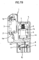
- the door lock switch assembly of the present invention includes a switch case 1, a switch cover 2 fitted to the switch case 1, a latch holder 3 elastically and rotatably fitted to one side portion of the switch case 1 for having restoring force in a door unlocking direction, a slide 4 on one side of the latch holder 3 in the switch case 1 to be movable in a direction the same with the hinge shaft in up and down direction for arresting or releasing the latch holder 3, a solenoid assembly fitted to a central portion of the switch case 1 for moving the slide 4 in the up and down directions, and a switching part located below the slide 4 for making switching by a seesaw action of switching terminals following the up and down movements of the slide 4.
- the latch holder 3 has a hook 3a formed at one side thereof for hooking a latch 16 at a front end of the door in a door locking, and a notch portion 3b with a V-notch 3c at a low portion of the latch holder 3.
- the stopper 4a has an inversed V shape and the V-notch 3c has a V shape having an angle greater than the stopper 4a.
- the switching part includes a movable contact 8 provided below the slide 4 in the switch case 1 to make a seesaw action, a fixed contact 9 provided on one side of the movable contact 8 parallel with the movable contact 8, having a fixed contact point corresponding to a moving contact point on the movable contact 8, a power supply terminal 10 provided on the other side of the movable contact 8 opposite to the fixed contact 9, for supplying the power to the solenoid assembly, and a torsion spring 11 provided in one side portion of the switch case, for providing a rotative force to the movable contact 8 to bring both of contact points of the movable contact 8 and the fixed contact 9 into contact with each other in the door locking.
- a compression spring or a tension spring may be provided instead of the torsion spring 11.
- the common terminal 8a has a supporting portion 8a-1 for supporting the movable contact 8 inside of the top end thereof, a projection 8a-5 outside of the supporting portion 8a-1 for preventing the movable contact 8 from being detached from the common terminal 8a, a bent portion 8a-4 and a recess 420b provided in the center along the length direction of the common terminal 8a to latch the common terminal 8a in a baffle formed inside the switch case 1 so that the common terminal 8a cannot fall down from the switch case 1.
- There is a wire connecting portion 8a-3 provided at one side of the top end of the common terminal 8a.
- the wire connecting portion 8a-3 extends to forward of the plunger 6 and is exposed to the outside of the switch cover 2.
- a projection 801 formed in the edge at the center of the movable contact 8 to prevent the movable contact 8 from being detached from the common contact 8a toward its length direction and to restrict a rotative angle of the movable contact 8.
- a switch pushing piece 4b provided on a lower part of the slide 4 in flush with the plunger 6 to push the movable contact 8 of the switching part when the slide 4 moves down.
- the contact points of the movable contact 8 and the fixed contact 9 are opened so that the contact points come away from each other.
- the bottom face of the switch pushing piece 4b has a slope side to substantially conform to an angle of the movable contact 8 slanted in horizontal direction when unlocking the door.
- the solenoid assembly includes a solenoid 5 fitted into a fastening part 1a formed in the central portion of the switch case 1, having a power supplying terminal exposed through the switch cover 2, a plunger 6 for being drawn into the solenoid 5 when the solenoid 5 is turned on, for moving the slide 4 backward, and a compression spring 7 provided on the outer circumferential surface of the plunger 6 to move the plunger 6 forward.
- a manual unlocking knob 4c formed at one side of the slide 4 as a unit with the strap 12 to pull the slide 4 down in a manual release of the door locking. The manual unlocking knob 4c is projected to the outside of the switch cover 2 through a through hole 2a in the switch cover 2.
- the top end of the stopper 4a on the slide 4 has a close contact with the bottom of the latch holder 3 blocking the slide 4 from moving upward any more, when the contact points in the switching part are opened, and kept a turned off state.
- the latch 16 can ndt be freed from the hook 3a on the latch holder 3. And, as the latch holder 3 is latched in the stopper 4a of the slide 4, preventing the latch holder 3 from returning to a position at the time of the door open, the latch 16 on the door 15 cannot also escape from the hook 3a of the latch holder 3, that achieves the locking of the door.
- Fig. 7b in the door locked state, when the user pushes a door lock release button(not shown) to supply the power to the solenoid 5, the plunger 6 moves down along the axis of the latch holder 3 while the plunger 6 compresses the compression spring 7 as the solenoid 5 draws in the plunger 6.
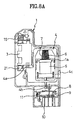
- the plunger 6, moving downward pushes the slide 4 downward from the moment the plunger 6 comes into contact with the lower sidewall of the slide 4 as shown in Fig. 8a until the stopper 4a on the slide 4 positioned in the V-notch 3c in the bottom portion of the latch holder 3 in a direction of the hinge shaft 21 of the latch holder 3 escapes from the bottom portion of the latch holder 3 fully.
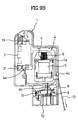
- the switch pushing piece 4b on the bottom of the slide 4 pushes an opposite side of the contact point of the movable contact 8, that leads the contact points between the fixed contact 9 and the movable contact 8 to open, when the torsion spring 11 accumulates the restoring force.
- the latch holder 3 rotates to return to the door opened state, the latch 16 latched in the hook 3a on the latch holder 3 escapes from the latch holder 3, in which the contact points between the fixed contact 9 and the movable contact 9 are opened, cutting off the power supplied to the driving part, the water supply valve, and the water discharge pump in the washing machine.
- the cover 20 When the power supply to the washing machine is failed due to power failure or an out of order of the washing machine in the door locked state, the cover 20 is opened, and the strap 12 inside the cover 20 is pulled to operate the door lock switch assembly manually, for unlocking the door.
- the knob 4c at one side of the slide 4 connected to the strap 12 is pulled directly, to facilitate an immediate moving down of the slide 4.
- the latch holder 3 returns to the door opened position by the torsion spring 11 as shown in Fig. 9c, resulting in the latch 16 in the hook 3a of the latch holder 3 released from the latch holder 16, to release the door unlocking.
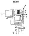
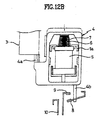
- Figs. 12a and 12b show structures of another switching part in a door lock switch assembly according to the present invention, in which Fig. 12a shows a contact point when a door is locked and Fig. 12b shows a contact point when a door is unlocked, and Fig. 13 is a sectional view showing connection state of a switch pushing piece and a movable contact, taken along line I - I of Fig. 12a.
- Figs. 12a and 12b shows a contact point when a door is unlocked
- Fig. 13 is a sectional view showing connection state of a switch pushing piece and a movable contact, taken along line I - I of Fig. 12a.
- a switching part of the door lock switch assembly according to another embodiment of the present invention will be described Figs. 12a and 12b, and Fig. 13.
- the closing/opening between the movable contact and the fixed contact are made by using, not a separate elastic member, such as the torsion spring, but an elasticity of the movable contact.
- the switching part includes a movable contact 8 having a pad at a fore end, provided on one side below the slide 4 to rotate around a hinge point by a pushing force of a switch pushing piece 4b disposed a distance away from the center of the slide, a fixed contact 9 provided to place a pad thereon over the pad on the movable contact 8 so that the contact points are opened when the switch pushing piece moves down, and a power supply terminal 10 provided at an opposite side of the movable contact 8 with reference to the fixed contact, for supplying power to the solenoid assembly.
- the movable contact 8 is provided to pass through the through hole. 410b in a fore end of the switch pushing piece 4b under the slide 4 at one side thereof, for providing the movement of the slide 4 directly to the movable contact 8 when the slide 4 moves, Also, the movable contact 8 has a free end at its top face and a fixing end fixed to the switch case 1.
- the movable contact 8 passed through the through hole 410b on the switch pushing piece 4b, rotates centered on the hinge point to make a positive switching action as the movable contact 8 is designed to receive the movement of the slide, directly.
- Fig. 14 is a sectional view showing another embodiment of Fig. 13.
- a through hole 420b with a hanging portion 41 1b for preventing the movable contact 8 from being fallen away may be formed at the front end of the switch pushing piece 4b to place the movable contact 8 in the through hole 420b, for transmitting the movement of the slide 4 to the movable contact 8.
- the slide is required to be formed of an insulating material, such as plastic.
- the structure of the switching part can be further simplified to reduce a number of components of the door lock switch assembly, with a consequential improvement in assembly.
- the aforementioned door lock switch assembly ofthe present invention has the following advantages.
- the latch holder and the slide 400 have a complicate structure for making and releasing an interference
- the latch holder and the slide of the present invention have a simple one. That is, in the related art door lock switch assembly, because the slide 400 moves back and forth sloped at a certain angle to a direction perpendicular to a direction of the hinge shaft of the latch holder 300 while the contact points are required to open/close in a direction perpendicular to the direction of movement of the slide 400, the structure becomes very complicate.
- the related art door lock assembly is required to take lots of factors into account in design the same because the related art slide 400 is required to be disposed on a horizontal line at the moment of a door locking even if the related art slide 400 makes movement slanted to the horizontal direction, while the contact points are opened/closed by an interference between the slide 400 and the movable contact in a direction perpendicular to the horizontal direction. Consequently, the related art door lock assembly has a complicated structure, to cause much interference between the components, that makes securing a reliability difficult as much.
- the door lock switch assembly of the present invention is a simple structure and has a good operation reliability as much since the slide 4 of the present invention has a simple liner movement.
- the door lock switch assembly of the present invention has a simple structure and an improved operation reliability in proportion to this.
- the door lock switch assembly of the present invention requires a small force in manual unlocking and can transmit the pulling force positively because the pulling force on the strap 12 exerts directly to the slide 4.
- the door lock switch assembly of the present invention has simple terminal fitting positions and arrangement, and minimum terminal lengths. That is, though the related art door lock switch assembly has lengthy switching terminals with bend, to require a complicate switch case structure for fixing the terminals, the door lock switch assembly has, not only short terminal lengths, but also simple case structures for fixing the terminals, particularly, the structures of the switching part can be simplified when the elasticity of the movable contact is utilized.
Landscapes
- Engineering & Computer Science (AREA)
- Textile Engineering (AREA)
- Push-Button Switches (AREA)
- Main Body Construction Of Washing Machines And Laundry Dryers (AREA)
Abstract
Description
Claims (22)
- A door lock switch assembly in a drum type washing machine comprising:a switch case;a switch cover fitted to the switch case;a latch holder rotatably, and elastically mounted in one side portion of the switch case for exerting a restoring force in a door open direction;a slide fitted to one side of the latch holder, for moving up or down in a direction the same with a hinge shaft of the latch holder to arrest or release the latch holder;a solenoid assembly mounted in a central portion of the switch case, for moving up or down the slide; and,a switching part located below the slide, for making a switching operation as a terminal thereof makes a seesaw action following the moving up or down of the slide.
- The door lock switch assembly as claimed in claim 1, wherein the latch holder includes;a hook at one side thereof for latching the latch at a fore end of the door, anda notch portion having a V-notch in a lower portion of the latch holder.
- The door lock switch assembly as claimed in claim 1, wherein the slide includes;
a stopper at one side thereof for making a close contact to a bottom of the latch holder when the door lock is released, and fitting into the V-notch in the lower portion of the latch holder when an interference to the latch holder is freed as the latch holder rotates greater than a certain angle by the latch in a door locking, for stopping any further movement of the latch holder, thereby preventing the latch holder from returning to a door opened position. - The door lock switch assembly as claimed in claim 3, wherein the stopper has an inversed V shape, and the V-notch has a V shape having an angle greater than the stopper, for minimizing a friction between the stopper and the V-notch when the slide moves down in releasing the latch holder, and for maintaining a positive stop of the latch holder by the stopper in the door locking,.
- The door lock switch assembly as claimed in claim 1, wherein the switching part includes;a movable contact provided below the slide in the switch case for making a seesaw action,a fixed contact provided on one side of the movable contact parallel with the movable contact, having a fixed contact point corresponding to a moving contact point on the movable contact, andan elastic member provided in one side portion of the switch case, for providing a rotative force to the movable contact to bring both of contact points of the movable contact and the fixed contact into contact with each other in the door locking.
- The door lock switch assembly as claimed in claim 1, wherein the switching part includes;a power supplying terminal at one side thereof, for supplying a power to the solenoid assembly.
- The door lock switch assembly as claimed in claim 6, wherein the power supplying terminal is provided away from the switching part in the switch case.
- The door lock switch assembly as claimed in claim 5, wherein the elastic member is a torsion spring.
- The door lock switch assembly as claimed in claim 5, wherein the elastic member is a coil spring.
- The door lock switch assembly as claimed in claim 1 or 5, wherein the slide includes a switch pushing piece on a bottom thereof on the same axis with the plunger for pushing the movable contact when the slide moves downward to open the contact points of the movable contact and the fixed contact.
- The door lock switch assembly as claimed in claim 10, wherein the switch pushing piece includes a bottom surface sloped substantially in conformity to an angle of the movable contact tilted in a horizontal direction in a door unlocking.
- The door lock switch assembly as claimed in claim 1, wherein the solenoid assembly includes;a solenoid inserted in, and fixed to a fastening part in the switch case, having a power supplying terminal exposed to outside of the switch case through the switch cover,a plunger for being drawn into the solenoid when the solenoid is turned on, to move the slide backward, anda compression spring provided on an outer circumference of the plunger to move the plunger forward.
- The door lock switch assembly as claimed in claim 1, wherein the slide includes a manual unlocking knob at one side thereof as one unit therewith for connecting with a strap to unlock the door from outside by the user forcibly.
- The door lock switch assembly as claimed in claim 11, wherein the manual unlocking knob is projected to outside of the switch cover through a through hole formed in the switch cover.
- The door lock switch assembly as claimed in claim 5, wherein supporting means for a seesaw movement of the movable contact is a common contact terminal fitted below the switch case.
- The door lock switch assembly as claimed in claim 15, wherein the common terminal includes a supporting portion inside of a top end thereof to support the movable contact, and a projection provided outside the supporting portion to prevent the movable contact from being fallen away from the common terminal.
- The door lock switch assembly as claimed in claim 15, wherein the common terminal includes a bent portion and a recess in a center along a length direction of the common terminal to latch the common terminal in a baffle formed inside the switch case so that the common terminal cannot be fallen off from the switch case.
- The door lock switch assembly as claimed in claim 15, wherein the common terminal includes a wire connecting portion at one side of the top end thereof, the wire connecting portion extending to forward of the plunger and being exposed to the outside of the switch cover.
- The door lock switch assembly as claimed in claim 15, wherein the movable contact includes a projection at an edge of the center thereof to prevent the movable contact from being moved away from the common terminal toward its length direction and to limit a rotative angle of the movable contact.
- The door lock switch assembly as claimed in claim 1, wherein the switching part includes;a movable contact having a pad at a fore end, provided on one side below the slide to rotate around a hinge point by a pushing force of a switch pushing piece disposed a distance away from the center of the slide,a fixed contact provided to place a pad thereon over the pad on the movable contact so that the contact points are opened when the switch pushing piece moves down, anda power supply terminal provided at an opposite side of the movable contact with reference to the fixed contact, for supplying power to the solenoid assembly.
- The door lock switch assembly as claimed in claim 20, wherein the movable contact is provided to pass through the through hole formed in the switch pushing piece below the slide for transmission of movements of the slide to the movable contact, directly.
- The door lock switch assembly as claimed in claim 21, wherein the switch pushing piece includes a recess at the front end thereof to permit the moving contact point to pass through the recess, the recess having a hanging portion for preventing the movable contact from being fallen off.
Applications Claiming Priority (4)
| Application Number | Priority Date | Filing Date | Title |
|---|---|---|---|
| KR9964943 | 1999-12-29 | ||
| KR1019990064943A KR100606695B1 (en) | 1999-12-29 | 1999-12-29 | Door Lock Switch Assembly for Drum Washing Machine |
| KR1020000002202A KR100335110B1 (en) | 2000-01-18 | 2000-01-18 | door lock switch assembly in drum-type washing machine |
| KR2000002202 | 2000-01-18 |
Publications (3)
| Publication Number | Publication Date |
|---|---|
| EP1113103A2 true EP1113103A2 (en) | 2001-07-04 |
| EP1113103A3 EP1113103A3 (en) | 2001-09-12 |
| EP1113103B1 EP1113103B1 (en) | 2004-06-09 |
Family
ID=26636584
Family Applications (1)
| Application Number | Title | Priority Date | Filing Date |
|---|---|---|---|
| EP20000204759 Expired - Lifetime EP1113103B1 (en) | 1999-12-29 | 2000-12-29 | Door lock switch assembly in drum type washing machine |
Country Status (6)
| Country | Link |
|---|---|
| US (2) | US6603377B2 (en) |
| EP (1) | EP1113103B1 (en) |
| JP (1) | JP2001204991A (en) |
| CN (1) | CN1143019C (en) |
| AU (1) | AU753113B2 (en) |
| DE (1) | DE60011381T2 (en) |
Cited By (7)
| Publication number | Priority date | Publication date | Assignee | Title |
|---|---|---|---|---|
| EP1619287A1 (en) * | 2004-07-13 | 2006-01-25 | C.R.F. Società Consortile per Azioni | Household appliance, namely a machine for washing and/or drying laundry, with a door block/release device that can be actuated electrically |
| CN1327102C (en) * | 2002-07-05 | 2007-07-18 | 乐金电子(天津)电器有限公司 | Door hinge for drum washing machine |
| EP2075365A1 (en) * | 2004-07-30 | 2009-07-01 | BITRON S.p.A. | A door locking device, in particular for a domestic appliance |
| CN101988258A (en) * | 2009-07-31 | 2011-03-23 | Lg电子株式会社 | Laundry treatment machine and control method thereof |
| CN101892571B (en) * | 2009-05-19 | 2012-04-25 | 温州天健电器有限公司 | Locking device of door of washing machine |
| EP2052122A4 (en) * | 2007-04-25 | 2014-10-08 | Dual Mechanics Co Ltd | A doorlock device for an electric home appliance |
| KR20170039198A (en) * | 2014-07-21 | 2017-04-10 | 비트론 에스.피.에이. | Doorlock system for household appliance provided with such system and operation method thereof |
Families Citing this family (29)
| Publication number | Priority date | Publication date | Assignee | Title |
|---|---|---|---|---|
| CN1316107C (en) * | 2002-07-05 | 2007-05-16 | 乐金电子(天津)电器有限公司 | Slide base fixator in door locking state for door lock switch assembly of drum washing machine |
| KR100484832B1 (en) * | 2002-11-28 | 2005-04-22 | 엘지전자 주식회사 | latch assembly of door in dry machine for clothes |
| ES2415664T3 (en) * | 2004-04-27 | 2013-07-26 | Marquardt Gmbh | Closure for a household appliance |
| DE102004060607B3 (en) * | 2004-12-16 | 2006-03-23 | Emz-Hanauer Gmbh & Co. Kgaa | Door locking system for household appliance may lock door in partially-open position and has detector determining state of door together with locking mechanism |
| DE102006047715A1 (en) * | 2006-10-09 | 2008-04-10 | Dometic Gmbh | Locking device for locking the interior of a device and device with locking device |
| US8246089B2 (en) * | 2006-10-28 | 2012-08-21 | Marquardt Gmbh | Lock for a household appliance |
| JP4038546B1 (en) * | 2007-06-15 | 2008-01-30 | テクノエクセル株式会社 | Washing tub door locking device for washing machine |
| DE102009019224B4 (en) * | 2008-04-30 | 2016-06-09 | Lg Electronics Inc. | Machine for treating textile and leather goods |
| JP5618517B2 (en) * | 2009-09-30 | 2014-11-05 | 日立アプライアンス株式会社 | Electric washing machine |
| KR100980441B1 (en) * | 2010-02-25 | 2010-09-07 | 두얼메카닉스 주식회사 | Door lock apparatus |
| JP2012075682A (en) * | 2010-10-01 | 2012-04-19 | Panasonic Corp | Door switch device of washing machine |
| IT1402638B1 (en) * | 2010-11-04 | 2013-09-13 | Bitron Spa | PERFORMED ACTUATOR MODULE, LOCKING-UNLOCKING SYSTEM FOR A DOOR OF HOUSEHOLD APPLIANCES AND ITS OPERATING METHOD. |
| ITRM20110118A1 (en) * | 2011-03-15 | 2012-09-16 | Bitron Spa | DOOR-LOCK DEVICE WITH PUSH-BUTTON OPENING. |
| EP2518243B1 (en) * | 2011-04-28 | 2019-06-12 | Electrolux Home Products Corporation N.V. | Electric household appliance comprising a door locking device |
| ITTO20110569A1 (en) * | 2011-06-29 | 2012-12-30 | Bitron Spa | LOCKING AND UNLOCKING DEVICE OF THE DOOR OF A HOUSEHOLD APPLIANCE |
| DE102013103451B4 (en) * | 2012-11-13 | 2016-07-28 | Stego-Holding Gmbh | Door contact switch, in particular for control cabinets |
| KR101463512B1 (en) | 2013-02-08 | 2014-11-20 | 두얼메카닉스 주식회사 | Door-lock Apparatus for Washing Machine |
| EP2781481B1 (en) * | 2013-03-19 | 2015-08-19 | KONE Corporation | A counterweight arrangement for an elevator |
| US10309136B2 (en) | 2013-10-11 | 2019-06-04 | Illinois Tool Works Inc. | Locking and unlocking mechanism for a door lock |
| CN103603170B (en) * | 2013-11-25 | 2015-11-11 | 温州天健电器有限公司 | A kind of door lock of washing machine |
| CN104805644B (en) * | 2014-01-26 | 2018-04-24 | 温州天健电器有限公司 | A kind of door lock of washing machine |
| EP2977498B1 (en) * | 2014-07-22 | 2017-10-25 | Electrolux Appliances Aktiebolag | Method for an emergency opening of a door locking device of a laundry washing and/or drying appliance |
| KR102512205B1 (en) | 2016-02-18 | 2023-03-22 | 삼성전자주식회사 | Door locking apparatus and washing machine having the same |
| CN110952287B (en) * | 2018-09-27 | 2023-05-16 | 青岛胶南海尔洗衣机有限公司 | Wall-mounted laundry treatment equipment |
| CN111946148B (en) * | 2019-05-14 | 2023-04-21 | 伊利诺斯工具制品有限公司 | Door lock |
| CN111956359A (en) * | 2020-08-25 | 2020-11-20 | 华北理工大学 | Oral surgery instrument box |
| CN115341365B (en) * | 2021-05-14 | 2025-07-29 | 青岛亚陆电子设备有限公司 | Novel door lock switch |
| EP4257741A4 (en) * | 2021-05-27 | 2024-07-17 | Samsung Electronics Co., Ltd. | WASHING MACHINE AND CONTROL METHODS THEREFOR |
| DE102023119510A1 (en) * | 2023-07-24 | 2025-01-30 | Emz-Hanauer Gmbh & Co. Kgaa | locking device for a door of a household appliance |
Family Cites Families (8)
| Publication number | Priority date | Publication date | Assignee | Title |
|---|---|---|---|---|
| US4365830A (en) * | 1980-06-09 | 1982-12-28 | Inglis Limited | Safety latch for washer closure |
| IT1136453B (en) * | 1980-07-24 | 1986-08-27 | Zanussi Grandi Impianti Spa | SAFETY DEVICE FOR OPENING THE DOOR OF WASHING MACHINES OR SIMILAR, IN PARTICULAR OF THE INDUSTRIAL TYPE |
| IT1223750B (en) * | 1988-08-02 | 1990-09-29 | Omp Off Meccano Plast | DOOR LOCKING DEVICE OF A WASHING MACHINE OR SCRUBBER |
| DE4034853C2 (en) * | 1990-11-02 | 1998-08-06 | Ltd Locking Technologies And D | Magnetic closure |
| DE4228100A1 (en) * | 1992-08-27 | 1994-03-03 | Ymos Ag Ind Produkte | Washing machine door lock - has automatic control for heating for bimetal strip to prevent opening while the appliance is in operation |
| US5520424A (en) * | 1995-01-30 | 1996-05-28 | U.S. Controls Copr. | Tamper-proof door switch and latch device |
| US5879036A (en) * | 1996-09-19 | 1999-03-09 | Moline; Steven S. | Door interlock for an appliance such as a washer |
| EP1039012A1 (en) * | 1999-03-22 | 2000-09-27 | Siber B.V. | Safety door lock system for use in particular on washing machines with an electronic system on board |
-
2000
- 2000-12-26 JP JP2000395327A patent/JP2001204991A/en active Pending
- 2000-12-28 AU AU72556/00A patent/AU753113B2/en not_active Ceased
- 2000-12-29 EP EP20000204759 patent/EP1113103B1/en not_active Expired - Lifetime
- 2000-12-29 DE DE2000611381 patent/DE60011381T2/en not_active Expired - Lifetime
- 2000-12-29 US US09/750,492 patent/US6603377B2/en not_active Expired - Fee Related
- 2000-12-29 CN CNB001310852A patent/CN1143019C/en not_active Expired - Fee Related
-
2001
- 2001-03-22 US US09/749,465 patent/US20020121783A1/en not_active Abandoned
Cited By (10)
| Publication number | Priority date | Publication date | Assignee | Title |
|---|---|---|---|---|
| CN1327102C (en) * | 2002-07-05 | 2007-07-18 | 乐金电子(天津)电器有限公司 | Door hinge for drum washing machine |
| EP1619287A1 (en) * | 2004-07-13 | 2006-01-25 | C.R.F. Società Consortile per Azioni | Household appliance, namely a machine for washing and/or drying laundry, with a door block/release device that can be actuated electrically |
| US7585006B2 (en) | 2004-07-13 | 2009-09-08 | C.R.F. Societa Consortile Per Azioni | Household appliance, namely a machine for washing and/or drying laundry, with a door block/release device that can be actuated electrically |
| EP2075365A1 (en) * | 2004-07-30 | 2009-07-01 | BITRON S.p.A. | A door locking device, in particular for a domestic appliance |
| EP1621658A3 (en) * | 2004-07-30 | 2009-07-01 | BITRON S.p.A. | A door locking device, in particular for a domestic appliance |
| EP2052122A4 (en) * | 2007-04-25 | 2014-10-08 | Dual Mechanics Co Ltd | A doorlock device for an electric home appliance |
| CN101892571B (en) * | 2009-05-19 | 2012-04-25 | 温州天健电器有限公司 | Locking device of door of washing machine |
| CN101988258A (en) * | 2009-07-31 | 2011-03-23 | Lg电子株式会社 | Laundry treatment machine and control method thereof |
| CN101988258B (en) * | 2009-07-31 | 2012-10-03 | Lg电子株式会社 | Laundry treatment machine and control method thereof |
| KR20170039198A (en) * | 2014-07-21 | 2017-04-10 | 비트론 에스.피.에이. | Doorlock system for household appliance provided with such system and operation method thereof |
Also Published As
| Publication number | Publication date |
|---|---|
| AU753113B2 (en) | 2002-10-10 |
| EP1113103B1 (en) | 2004-06-09 |
| US20020056998A1 (en) | 2002-05-16 |
| CN1143019C (en) | 2004-03-24 |
| DE60011381T2 (en) | 2005-06-23 |
| US6603377B2 (en) | 2003-08-05 |
| US20020121783A1 (en) | 2002-09-05 |
| CN1301894A (en) | 2001-07-04 |
| AU7255600A (en) | 2001-07-12 |
| JP2001204991A (en) | 2001-07-31 |
| DE60011381D1 (en) | 2004-07-15 |
| EP1113103A3 (en) | 2001-09-12 |
Similar Documents
| Publication | Publication Date | Title |
|---|---|---|
| EP1113103B1 (en) | Door lock switch assembly in drum type washing machine | |
| US6598265B2 (en) | Handle structure of an apparatus for opening and closing a window | |
| US6390518B1 (en) | Latching mechanism for an appliance door | |
| US7299809B2 (en) | Dishwasher having a lock with an elastic coupling | |
| JPH10286394A (en) | Door lock device for washing machine | |
| KR100606695B1 (en) | Door Lock Switch Assembly for Drum Washing Machine | |
| US4947516A (en) | Lid retainer mechanism for automatic washer | |
| KR200277539Y1 (en) | hose reel | |
| US6118090A (en) | Self-aligning lid switch for laundry machines | |
| KR100335110B1 (en) | door lock switch assembly in drum-type washing machine | |
| KR960002302B1 (en) | Household appliance fastening device particularly for a washing machine | |
| JP4207257B2 (en) | Washing machine | |
| JPS582315Y2 (en) | Lid pivot device | |
| JP2000051573A (en) | Washing machine | |
| KR100201855B1 (en) | Electronic Automatic Opening Door Locker in Drum Washing Machine | |
| JP4178611B2 (en) | Washing machine | |
| JPH1057674A (en) | Washing machine | |
| JP2000051567A (en) | Washing machine | |
| KR200206164Y1 (en) | Apparatus for opening and closing operating panel of facsimile | |
| JP2002282578A (en) | Washing machine lid lock device | |
| JP2000051571A (en) | Washing machine | |
| KR200146377Y1 (en) | Flat handle for door | |
| JPS58200784A (en) | Safety device for dehydrating and washing machines | |
| KR920008495Y1 (en) | Door lock apparatus of drum washer | |
| JP2000051574A (en) | Washing machine |
Legal Events
| Date | Code | Title | Description |
|---|---|---|---|
| PUAI | Public reference made under article 153(3) epc to a published international application that has entered the european phase |
Free format text: ORIGINAL CODE: 0009012 |
|
| AK | Designated contracting states |
Kind code of ref document: A2 Designated state(s): AT BE CH CY DE DK ES FI FR GB GR IE IT LI LU MC NL PT SE TR Kind code of ref document: A2 Designated state(s): DE GB IT |
|
| AX | Request for extension of the european patent |
Free format text: AL;LT;LV;MK;RO;SI |
|
| PUAL | Search report despatched |
Free format text: ORIGINAL CODE: 0009013 |
|
| AK | Designated contracting states |
Kind code of ref document: A3 Designated state(s): AT BE CH CY DE DK ES FI FR GB GR IE IT LI LU MC NL PT SE TR |
|
| AX | Request for extension of the european patent |
Free format text: AL;LT;LV;MK;RO;SI |
|
| 17P | Request for examination filed |
Effective date: 20011128 |
|
| AKX | Designation fees paid |
Free format text: DE GB IT |
|
| 17Q | First examination report despatched |
Effective date: 20021217 |
|
| GRAP | Despatch of communication of intention to grant a patent |
Free format text: ORIGINAL CODE: EPIDOSNIGR1 |
|
| GRAS | Grant fee paid |
Free format text: ORIGINAL CODE: EPIDOSNIGR3 |
|
| GRAA | (expected) grant |
Free format text: ORIGINAL CODE: 0009210 |
|
| AK | Designated contracting states |
Kind code of ref document: B1 Designated state(s): DE GB IT |
|
| REG | Reference to a national code |
Ref country code: GB Ref legal event code: FG4D |
|
| REF | Corresponds to: |
Ref document number: 60011381 Country of ref document: DE Date of ref document: 20040715 Kind code of ref document: P |
|
| PLBE | No opposition filed within time limit |
Free format text: ORIGINAL CODE: 0009261 |
|
| STAA | Information on the status of an ep patent application or granted ep patent |
Free format text: STATUS: NO OPPOSITION FILED WITHIN TIME LIMIT |
|
| 26N | No opposition filed |
Effective date: 20050310 |
|
| PGFP | Annual fee paid to national office [announced via postgrant information from national office to epo] |
Ref country code: GB Payment date: 20161110 Year of fee payment: 17 Ref country code: DE Payment date: 20161107 Year of fee payment: 17 |
|
| PGFP | Annual fee paid to national office [announced via postgrant information from national office to epo] |
Ref country code: IT Payment date: 20161214 Year of fee payment: 17 |
|
| REG | Reference to a national code |
Ref country code: DE Ref legal event code: R119 Ref document number: 60011381 Country of ref document: DE |
|
| GBPC | Gb: european patent ceased through non-payment of renewal fee |
Effective date: 20171229 |
|
| PG25 | Lapsed in a contracting state [announced via postgrant information from national office to epo] |
Ref country code: IT Free format text: LAPSE BECAUSE OF NON-PAYMENT OF DUE FEES Effective date: 20171229 Ref country code: DE Free format text: LAPSE BECAUSE OF NON-PAYMENT OF DUE FEES Effective date: 20180703 |
|
| PG25 | Lapsed in a contracting state [announced via postgrant information from national office to epo] |
Ref country code: GB Free format text: LAPSE BECAUSE OF NON-PAYMENT OF DUE FEES Effective date: 20171229 |