EP1112030B1 - Verfahren und vorrichtung zur visualisierung der ausrichtung von therapeutischen schallwellen auf einen zu behandelnden bereich - Google Patents
Verfahren und vorrichtung zur visualisierung der ausrichtung von therapeutischen schallwellen auf einen zu behandelnden bereich Download PDFInfo
- Publication number
- EP1112030B1 EP1112030B1 EP99955693A EP99955693A EP1112030B1 EP 1112030 B1 EP1112030 B1 EP 1112030B1 EP 99955693 A EP99955693 A EP 99955693A EP 99955693 A EP99955693 A EP 99955693A EP 1112030 B1 EP1112030 B1 EP 1112030B1
- Authority
- EP
- European Patent Office
- Prior art keywords
- sound
- region
- treatment
- displayed
- sound waves
- Prior art date
- Legal status (The legal status is an assumption and is not a legal conclusion. Google has not performed a legal analysis and makes no representation as to the accuracy of the status listed.)
- Expired - Lifetime
Links
Images
Classifications
-
- A—HUMAN NECESSITIES
- A61—MEDICAL OR VETERINARY SCIENCE; HYGIENE
- A61B—DIAGNOSIS; SURGERY; IDENTIFICATION
- A61B17/00—Surgical instruments, devices or methods, e.g. tourniquets
- A61B17/22—Implements for squeezing-off ulcers or the like on the inside of inner organs of the body; Implements for scraping-out cavities of body organs, e.g. bones; Calculus removers; Calculus smashing apparatus; Apparatus for removing obstructions in blood vessels, not otherwise provided for
- A61B17/225—Implements for squeezing-off ulcers or the like on the inside of inner organs of the body; Implements for scraping-out cavities of body organs, e.g. bones; Calculus removers; Calculus smashing apparatus; Apparatus for removing obstructions in blood vessels, not otherwise provided for for extracorporeal shock wave lithotripsy [ESWL], e.g. by using ultrasonic waves
- A61B17/2256—Implements for squeezing-off ulcers or the like on the inside of inner organs of the body; Implements for scraping-out cavities of body organs, e.g. bones; Calculus removers; Calculus smashing apparatus; Apparatus for removing obstructions in blood vessels, not otherwise provided for for extracorporeal shock wave lithotripsy [ESWL], e.g. by using ultrasonic waves with means for locating or checking the concrement, e.g. X-ray apparatus, imaging means
-
- A—HUMAN NECESSITIES
- A61—MEDICAL OR VETERINARY SCIENCE; HYGIENE
- A61B—DIAGNOSIS; SURGERY; IDENTIFICATION
- A61B34/00—Computer-aided surgery; Manipulators or robots specially adapted for use in surgery
- A61B34/10—Computer-aided planning, simulation or modelling of surgical operations
- A61B2034/101—Computer-aided simulation of surgical operations
- A61B2034/102—Modelling of surgical devices, implants or prosthesis
-
- A—HUMAN NECESSITIES
- A61—MEDICAL OR VETERINARY SCIENCE; HYGIENE
- A61B—DIAGNOSIS; SURGERY; IDENTIFICATION
- A61B34/00—Computer-aided surgery; Manipulators or robots specially adapted for use in surgery
- A61B34/10—Computer-aided planning, simulation or modelling of surgical operations
- A61B2034/107—Visualisation of planned trajectories or target regions
-
- A—HUMAN NECESSITIES
- A61—MEDICAL OR VETERINARY SCIENCE; HYGIENE
- A61B—DIAGNOSIS; SURGERY; IDENTIFICATION
- A61B34/00—Computer-aided surgery; Manipulators or robots specially adapted for use in surgery
- A61B34/10—Computer-aided planning, simulation or modelling of surgical operations
-
- A—HUMAN NECESSITIES
- A61—MEDICAL OR VETERINARY SCIENCE; HYGIENE
- A61B—DIAGNOSIS; SURGERY; IDENTIFICATION
- A61B34/00—Computer-aided surgery; Manipulators or robots specially adapted for use in surgery
- A61B34/20—Surgical navigation systems; Devices for tracking or guiding surgical instruments, e.g. for frameless stereotaxis
-
- A—HUMAN NECESSITIES
- A61—MEDICAL OR VETERINARY SCIENCE; HYGIENE
- A61B—DIAGNOSIS; SURGERY; IDENTIFICATION
- A61B8/00—Diagnosis using ultrasonic, sonic or infrasonic waves
- A61B8/08—Detecting organic movements or changes, e.g. tumours, cysts, swellings
- A61B8/0833—Detecting organic movements or changes, e.g. tumours, cysts, swellings involving detecting or locating foreign bodies or organic structures
Definitions
- the invention relates to a method for visualization the alignment of therapeutic sound waves on one to be treated Area as well as a device for implementation this procedure.
- intra- or extracorporeally generated pulsed pressure or shock waves used during continuous sound waves e.g. be used for heating the tissue.
- sound wave focus - towards treatment region to be treated or to be processed align. This can be done by moving the sound source and / or the patient and by influencing the spatial pressure distribution in the sound field and thus due to a focus shift relative to the sound source respectively.
- positioning is said to be from a series of Reasons - for example for liability reasons - in the Usually not automatically, but by the user, that is for example a doctor. So that User can do the positioning is one numerical or graphic display required that it allows the user to focus the sound wave on the treatment region align.
- Pressure waves are displayed e.g. by fading in a crosshair in a two-dimensional X-ray or ultrasound image:
- this information is numerical displayed as a distance in a spatial coordinate system.
- the positioning becomes one time consuming process since the user does this numeric Must convert information into a spatial movement.
- FIG. 4 DE-A-195 12 956 Another positioning display is shown in Fig. 4 DE-A-195 12 956. Here the location the sound wave focus in one plane and one on it vertical axis shown.
- the disadvantage is here that the user always has two movable brands must keep an eye on in order to assess the spatial location. Misinterpretations are avoided with this - not pseudo-three-dimensional - ad avoided, but the implementation of the image information does not allow sufficient quick and fatigue-free positioning.
- Document US-A-5 526 814 describes a method for visualizing the alignment of therapeutic sound waves on an area to be treated Using a display unit with a screen on which the orientation of the symbolizes therapeutic sound waves in relation to the area to be treated is shown, on the screen the sound wave source and the area, through which the sound waves propagate, as well as the area to be treated are shown in perspective by assigning physical figures, the perspective view when changing the location or the orientation of the Sound wave source and / or the treatment area changes correctly.
- the invention has for its object a method to visualize the alignment of therapeutic Sound waves on one to be treated Area as well as a device for implementation to specify this method in which the positioning information through an easy to interpret graphic display takes place.
- the invention is based on the following knowledge:
- the approach according to the invention is based on knowledge designing three-dimensional bodies on computers ("computer aided design", "CAD") and the one on it constructive application of artificial reality (“virtual reality ",” VR “).
- CAD computer aided design
- VR virtual reality
- the basic principle of VR presentation techniques is that the perspective the body shown with the location of the viewer changes. In contrast to the stereoscopic representation nothing arises from the still picture alone spatial impression, since left and right eye received the same information.
- the human brain can draw from such an image sequence Conclusions about the size and relative location of the displayed objects. It is the same if you allow the viewer to place objects in the Seemingly seizing scene (virtual hand) and her to move relative to each other. The similarity to the real one with the scene created on the screen the viewer has the illusion that he is there actually in the scene ("immersion", immersion).
- the basic idea of the invention is such representation techniques for positioning the sound wave focus to use a treatment region.
- the sound wave source is shown on the screen and the area through which the sound waves pass spread out, as well as the one to be treated Area (i. F. Treatment area) in perspective represented by assignment of physical figures.
- there the perspective view changes with a change the location or the orientation of the sound wave source and / or the treatment area and / or the Location or the orientation of the screen with correct movement.
- the illustration shows the real position of the sound source and the treatment region correctly in perspective, to give the user an accurate impression of to give the size and spacing of the figures.
- the focus is on the treatment region Figure corresponding to the sound wave focus in the illustrated Scene just like in reality.
- the user receives the impression that it is in the virtual scene and list the sound source there the treatment region (immersion, virtual hand).
- those of one Measuring system which is the relative location between sound source and treatment area or location device, received signals about the spatial location of the sound source almost in real time in an equivalent virtual Movement implemented.
- the focused therapeutic sound waves are represented as a cone, the mantle of which such as the transition between the focused wave and the edge diffraction wave equivalent.
- the mantle of the cone shown With further training the mantle of the cone shown with such a openwork surface depicting the treatment area is not covered.
- the Sheath of the cone shown shown semitransparent become.
- the treatment area will roughly the size of the Sound waves have a therapeutic effect unfold.
- the treatment area as a sphere or ellipsoid being represented.
- a particularly preferred embodiment of the invention Method has a proximity indicator, the approximation or correspondence of the area, in which the sound waves are therapeutic or processing Have an effect on the treatment area indicates.
- the user receives a quantitative Information on how exactly he is positioning performed.
- the approach indicator can be audible - for example by changing the pitch (tone frequency) and / or the tone repetition frequency.
- the proximity indicator can be viewed through an envelope Color done in at least one of the physical Figures is shown. It is also possible that the proximity display is numerical.
- the objects shown have surfaces ( "Rendering"). It is an advantage if on the surfaces shown, light incidence and light reflection is simulated, such as in a endoscopic or surgical intervention would.
- a virtual lighting source on the Ceiling of the treatment or processing room arranged his.
- a virtual Illumination source in the center of the treatment area be arranged.
- a second light source is in the middle the treatment region, so that there is a brightening in the Area of the cone tip results when you hit the target approaches. This creates undesirable strong shadows avoided when approaching the target from above.
- Fixed parts can be around a treatment couch and / or a positioning device for a location device - for example an X-ray C-arm or an ultrasound locating device - act.
- the location of the treatment area can be dependent from the output signal of a locating device being represented.
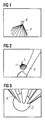
- Fig. 1 shows how the distribution of sound pressure through a broken cone 1 is shown.
- 2nd is the area referred to the sound wave field to be aligned, and the one with this one Figure not shown sound wave focus "for Cover "should be brought.
- the one used by the user usually already existing cone of entry.
- the cone shell corresponds to the transition between focused Wave and edge diffraction wave and thus represents in First approximation represents the area within which one therapeutically effective sound energy is transmitted.
- the interruption of the cone jacket serves to Avoid covering the treatment region 2.
- a another possibility for this is the semi-transparent Representation of the cone ("rendering" in "transparent mode").
- the sound wave focus can not only be the tip of the cone 1, but also clearly in the form of a sphere or an ellipsoid of revolution, whose Size corresponds to the size of the sound wave focus. The user is thus able to achieve the positioning accuracy achieved estimate.
- sphere or ellipsoid sound wave focus
- treatment region 2 each other.
- 2 explains one possibility for the representation of the user location.
- 2 shows a treatment scene for this purpose shown in which an X-ray C-arm 3 is shown.
- the C-arm 3 gives the user one Orientation about its location in the scene.
- a touch sensitive The scene (touch screen) or the like can be rotated become. By comparing it to its true location the user chooses the perspective that his actual Location corresponds so that it is in a real Scene can work without being between screen display and actual treatment scenario would have to "rethink”.
- magnification (Zoom function)
- zoom function magnification
- the magnification changed so that the user of the The impression arises that he is approaching the treatment region himself.
- the effect of immersion amplified on the other hand, fine-tuning improved on the last millimeters of approach.
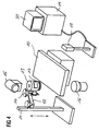
- Fig. 4 shows a typical configuration for a treatment place with sound waves, as in the context of Invention is further developed.
- the treatment station has a patient couch 10, for positioning a patient, not shown horizontally displaceable in a manner known per se, is adjustable in height and / or rotatable.
- Tripod 11 On one Tripod 11 is an adjustable holding arm 12 for one therapeutic sound source 13 attached.
- the sound source 13 can be formed in a manner known per se and for example to destroy Body concretions, for pain treatment, for Treatment of the heart, for warming up Serve body regions or the like.
- a brake for the movements of the sound source 13 denotes the precise adjustment of the Sound source 13 relative to the patient or the patient bed 10 allowed.
- the sound source 13 can thus in desired relative to one on the patient table 10 lying patients by hand or if necessary with a servo adjustment.
- An x-ray tube 15 with an image intensifier 16, the for example attached to a C-arm, not shown can be used to record what is to be treated Area, for example a body concrement in the kidney, bladder or urinary tract a patient lying on the patient couch 10. Additionally or alternatively, other location systems, as provided by ultrasound location systems his.
- a sensor 17 is attached to the sound source 13, of the detection of the position of the sound source 13 relative to the patient couch 10 or the recognized one to be treated Area of the patient using a position detection system 18 allows the output signal to an evaluation and control unit, for example a computer system 19 is created which has a screen 20, on which by means of the Process-appropriate displays for an operator, in the case of medical applications one Doctor are represented. Suitable ones are not shown Input options, such as a keyboard, a Mouse control, a touch screen or a voice control of the system 19.
- the position detection system delivers during the treatment process 18 continuous data on the location the sound source 13 relative to the couch 10 to the control and Evaluation unit or the computer system 19.
- the computer program of the computer system 19 includes fast algorithms to calculate the perspective ("VR programs”), for creating a surface ("rendering") and to calculate the light reflection ("ray tracing ").
- VR programs for creating a surface
- ray tracing the light reflection
- Such programs are from other - non-medical - applications - for example CAD applications - known, so that at this point on the Training of such programs not discussed in detail must become.
- the position data on the screen 20 updated scene updated several times per second, so that the real-time simulation required for an immersion results.
- Image intensifier 16 of the x-ray device or an ultrasound transducer recorded and to improve orientation are shown in the scene with.
- images can be created with the same computer system e.g. of the X-ray system read in ("frame grabber") and off the position of the image intensifier in two projections determine the spatial location of the treatment region, such as this is described in DE-A-195 12 956.
- Quantitative information about the distance of the cone tip to the center of the sound wave focus transmit in different ways. For example, lets a numerical display of the distance appears.
- Another possibility is an acoustic signal that at longer distances with a lower repetition frequency sounds. As the distance decreases, the repetition frequency becomes continuously increased. When falling below one the pitch is raised.
- a third possibility is a color change of cone and / or ball that is continuous or at The distance is below a predetermined distance. It can also be provided that if the value falls short of a predetermined target distance generates a signal is that on the braking device 14 for the movements the sound source 13 acts.
- a further solution is to the position signal to a motorized adjustment of the Let sound source 13 act or the spatial To influence the pressure distribution of the sound source and thus automating the positioning.
- Another embodiment provides for a three-dimensional one Representation of the inside of the body, such as by means of CT, NMR or ultrasound is.
- the cone figure can be superimposed on this representation be related to the location of the sound wave field to represent anatomical structures. This can improve therapy and reduce side effects, for example by avoiding gas-filled ones Cavities or bone structures in the sound field are located.
Description
- Fig. 1
- die Darstellung der Verteilung des Schalldrucks durch einen durchbrochenen Kegel,
- Fig. 2
- eine Behandlungsszene, in die zur Erläuterung der Eingabemöglichkeit für den Benutzerstandort ein Röntgen C-Bogen eingeblendet ist,
- Fig. 3
- eine Darstellung zur Erläuterung der Annäherung des therapeutischen Schallwellenfeldes an die Behandlungsregion, und
- Fig. 4
- eine Vorrichtung zur Durchführung des erfindungsgemäßen Verfahrens.
Claims (19)
- Verfahren zur Visualisierung der Ausrichtung von fokussierten therapeutischen Schallwellen auf einen zu behandelnden Bereich unter Verwendung einer Anzeigeeinheit mit einem Bildschirm, auf dem die Ausrichtung der fokussierten therapeutischen Schallwellen in Bezug auf den zu behandelnden Bereich symbolisiert dargestellt wird, wobei
auf dem Bildschirm die Schallwellenquelle und der Raumbereich, durch den sich die Schallwellen ausbreiten, sowie der zu behandelnde Bereich, i.f. Behandlungsbereich, perspektivisch durch Zuordnung körperlicher Figuren dargestellt werden, und sich die perspektivische Ansicht bei einer Änderung des Ortes bzw. der Ausrichtung der Schallwellenquelle und/oder des Behandlungsbereichs und/oder des Standortes bzw. der Orientierung des Bildschirmes bewegungsrichtig ändert, wobei die fokussierten therapeutischen Schallwellen als Kegel dargestellt werden, dessen Mantel in etwa dem Übergang zwischen fokussierter Welle und Randbeugungswelle entspricht und wobei der Behandlungsbereich in etwa in der Größe dargestellt wird, in der die Schallwellen eine therapeutische Wirkung entfalten. - Verfahren nach Anspruch 1,
dadurch gekennzeichnet, dass sich die perspektivische Ansicht bei einer Änderung des Standortes einer Bedienungsperson entsprechend der Ansichtsänderung der Szene für die Bedienungsperson ändert bzw. manuell ändern lässt. - Verfahren nach einem der Ansprüche 1 oder 2,
dadurch gekennzeichnet, dass der Mantel des dargestellten Kegels mit einer derart durchbrochenen Oberfläche dargestellt wird, dass der Behandlungsbereich nicht verdeckt wird. - Verfahren nach einem der Ansprüche 1 oder 2,
dadurch gekennzeichnet, dass der Mantel des dargestellten Kegel semi-transparent dargestellt wird. - Verfahren nach einem der Ansprüche 1-4,
dadurch gekennzeichnet, dass bei fokussierten Schallwellen der Behandlungsbereich als Kugel oder Ellipsoid dargestellt wird. - Verfahren nach einem der Ansprüche 1 bis 5,
dadurch gekennzeichnet, dass eine Annäherungs-Anzeige vorgesehen ist, die die Annäherung bzw. Übereinstimmung des Bereichs, in dem die Schallwellen eine therapeutische Wirkung entfalten, an den Behandlungsbereich angibt. - Verfahren nach Anspruch 6,
dadurch gekennzeichnet, dass die Annäherungsanzeige akustisch erfolgt. - Verfahren nach Anspruch 7,
dadurch gekennzeichnet, dass die Annäherungsanzeige durch eine Veränderung der Tonhöhe (Tonfrequenz) und/oder der Ton-Wiederholfrequenz erfolgt. - Verfahren nach Anspruch 6,
dadurch gekennzeichnet, dass die Annäherungsanzeige durch einen Umschlag der Farbe erfolgt, in der wenigstens eine der körperlichen Figuren dargestellt ist. - Verfahren nach Anspruch 6,
dadurch gekennzeichnet, dass die Annäherungsanzeige numerisch erfolgt. - Verfahren nach einem der Ansprüche 1 bis 10,
dadurch gekennzeichnet, dass auf den dargestellten Oberflächen Lichteinfall und Lichtreflexion simuliert wird. - Verfahren nach Anspruch 11,
dadurch gekennzeichnet, dass eine virtuelle Beleuchtungsquelle an der Decke des Behandlungs raums angeordnet ist. - Verfahren nach Anspruch 11 oder 12,
dadurch gekennzeichnet, dass eine virtuelle Beleuchtungsquelle im Zentrum des Behandlungsbereichs angeordnet ist. - Verfahren nach einem der Ansprüche 1 bis 13,
dadurch gekennzeichnet, dass in das dargestellte Bild ortsfeste Teile des Behandlungs raums eingeblendet werden - Verfahren nach Anspruch 14,
dadurch gekennzeichnet, dass es sich bei den ortsfesten Teilen um eine Behandlungsliege und/oder eine Positioniereinrichtung für eine Ortungseinrichtung handelt. - Verfahren nach Anspruch 15,
dadurch gekennzeichnet, dass die Positioniereinrichtung ein Röntgen-C-Bogen ist. - Verfahren nach einem der Ansprüche 1 bis 16,
dadurch gekennzeichnet, dass eine Zoomfunktion realisiert ist, mit der die Umgebung des Behandlungsbereichs vergrößert dargestellt werden kann. - Verfahren nach einem der Ansprüche 1 bis 19,
dadurch gekennzeichnet, dass die Lage des Behandlungsbereichs in Abhängigkeit von dem Ausgangssignal einer Ortungseinrichtung dargestellt wird. - Vorrichtung zur Durchführung des Verfahrens nach einem der Ansprüche 1 bis 18,
dadurch gekennzeichnet, dass ein Positionserfassungssystem (17,18) vorgesehen ist, das die Lage der Schall quelle (13) relativ zu dem zu therapierenden Bereich erfasst, und dessen Ausgangssignal an eine Auswerte- und Steuereinheit (19) mit einem Bildschirm (20) angelegt ist, auf dem die Zuordnung zwischen Schallwellenfokus und zu behandelndem Bereich perspektivisch durch Zuordnung körperlicher Figuren dargestellt ist.
Applications Claiming Priority (3)
| Application Number | Priority Date | Filing Date | Title |
|---|---|---|---|
| DE19841951A DE19841951C2 (de) | 1998-09-14 | 1998-09-14 | Verfahren zur Visualisierung der Ausrichtung von therapeutischen Schallwellen auf einen zu behandelnden bzw. zu bearbeitenden Bereich |
| DE19841951 | 1998-09-14 | ||
| PCT/DE1999/002913 WO2000015121A1 (de) | 1998-09-14 | 1999-09-14 | Verfahren und vorrichtung zur visualisierung der ausrichtung von therapeutischen schallwellen auf einen zu behandelnden bzw. zu bearbeitenden bereich |
Publications (2)
| Publication Number | Publication Date |
|---|---|
| EP1112030A1 EP1112030A1 (de) | 2001-07-04 |
| EP1112030B1 true EP1112030B1 (de) | 2004-12-01 |
Family
ID=7880861
Family Applications (1)
| Application Number | Title | Priority Date | Filing Date |
|---|---|---|---|
| EP99955693A Expired - Lifetime EP1112030B1 (de) | 1998-09-14 | 1999-09-14 | Verfahren und vorrichtung zur visualisierung der ausrichtung von therapeutischen schallwellen auf einen zu behandelnden bereich |
Country Status (5)
| Country | Link |
|---|---|
| US (1) | US6616618B2 (de) |
| EP (1) | EP1112030B1 (de) |
| JP (1) | JP4691254B2 (de) |
| DE (2) | DE19841951C2 (de) |
| WO (1) | WO2000015121A1 (de) |
Families Citing this family (13)
| Publication number | Priority date | Publication date | Assignee | Title |
|---|---|---|---|---|
| US7862512B2 (en) * | 2005-08-29 | 2011-01-04 | Unex Corporation | Blood vessel endothelium function evaluating apparatus provided with an electronic control device |
| US20070093732A1 (en) * | 2005-10-26 | 2007-04-26 | David Venturi | Vibroacoustic sound therapeutic system and method |
| CN100563753C (zh) * | 2005-12-27 | 2009-12-02 | 重庆融海超声医学工程研究中心有限公司 | 一种mri引导的高强度聚焦超声治疗系统 |
| DE102006022141A1 (de) * | 2006-05-11 | 2007-11-15 | Siemens Ag | Verfahren zur Ausrichtung von von einem Röntgenstrahler abstrahlbaren Röntgenstrahlen auf eine Detektorfläche eines Röntgendetektors |
| US7610079B2 (en) * | 2006-07-25 | 2009-10-27 | Ast Gmbh | Shock wave imaging system |
| DE102006050781A1 (de) * | 2006-10-27 | 2008-04-30 | Ast Gmbh | Vorrichtung zur räumlichen Positionierung eines Gerätes |
| EP2105098B1 (de) * | 2008-03-27 | 2010-10-27 | Storz Medical Ag | Druckwellentherapievorrichtung mit integrierter Röntgenanlage |
| US8049175B2 (en) * | 2009-05-01 | 2011-11-01 | Saint-Gobain Ceramics & Plastics, Inc. | Scintillator operation and control |
| FR2954903B1 (fr) | 2010-01-05 | 2012-03-02 | Edap Tms France | Procede et appareil de localisation et de visualisation d'une cible par rapport a un point focal d'un systeme de traitement |
| EP3047809B1 (de) | 2015-01-23 | 2022-04-13 | Storz Medical Ag | Extrakorporales stosswellenlithotripsiesystem mit offline-ultraschallortung |
| US11484724B2 (en) | 2015-09-30 | 2022-11-01 | Btl Medical Solutions A.S. | Methods and devices for tissue treatment using mechanical stimulation and electromagnetic field |
| EP3875048B1 (de) | 2020-03-04 | 2022-05-04 | Storz Medical AG | Stosswellentherapiesystem mit 3d-steuerung |
| CN112435441B (zh) * | 2020-11-19 | 2022-08-16 | 维沃移动通信有限公司 | 睡眠检测方法和可穿戴电子设备 |
Family Cites Families (10)
| Publication number | Priority date | Publication date | Assignee | Title |
|---|---|---|---|---|
| US4829986A (en) * | 1986-08-22 | 1989-05-16 | Siemens Aktiengesellschaft | Lithotripsy work station |
| DE3811872A1 (de) * | 1988-04-09 | 1989-10-26 | Wolf Gmbh Richard | Einrichtung zum orten und zerstoeren von koerperinneren objekten mit ultraschall |
| US5435311A (en) * | 1989-06-27 | 1995-07-25 | Hitachi, Ltd. | Ultrasound therapeutic system |
| CA2003497C (en) * | 1989-11-21 | 1999-04-06 | Michael M. Greenberg | Probe-correlated viewing of anatomical image data |
| US5687737A (en) * | 1992-10-09 | 1997-11-18 | Washington University | Computerized three-dimensional cardiac mapping with interactive visual displays |
| US5460595A (en) * | 1993-06-01 | 1995-10-24 | Dynatronics Laser Corporation | Multi-frequency ultrasound therapy systems and methods |
| US5526814A (en) * | 1993-11-09 | 1996-06-18 | General Electric Company | Automatically positioned focussed energy system guided by medical imaging |
| DE19512956C2 (de) * | 1995-04-10 | 2001-07-05 | Storz Medical Ag Kreuzlingen | Vorrichtung zur Lageerfassung mittels Röntgenstrahlen in einem therapeutischen Druckwellengerät |
| DE19515748A1 (de) * | 1995-04-28 | 1996-10-31 | Siemens Ag | Gerät zur Behandlung mit akustischen Wellen |
| DE19548000C1 (de) * | 1995-12-21 | 1997-07-10 | Dornier Medizintechnik | Vorrichtung zur Ortung von Konkrementen im Körper eines Patienten |
-
1998
- 1998-09-14 DE DE19841951A patent/DE19841951C2/de not_active Expired - Fee Related
-
1999
- 1999-09-14 WO PCT/DE1999/002913 patent/WO2000015121A1/de active IP Right Grant
- 1999-09-14 DE DE59911202T patent/DE59911202D1/de not_active Expired - Lifetime
- 1999-09-14 JP JP2000569707A patent/JP4691254B2/ja not_active Expired - Fee Related
- 1999-09-14 EP EP99955693A patent/EP1112030B1/de not_active Expired - Lifetime
-
2001
- 2001-03-13 US US09/805,406 patent/US6616618B2/en not_active Expired - Fee Related
Also Published As
| Publication number | Publication date |
|---|---|
| JP2002524185A (ja) | 2002-08-06 |
| DE59911202D1 (de) | 2005-01-05 |
| EP1112030A1 (de) | 2001-07-04 |
| DE19841951C2 (de) | 2002-08-29 |
| JP4691254B2 (ja) | 2011-06-01 |
| US6616618B2 (en) | 2003-09-09 |
| WO2000015121A1 (de) | 2000-03-23 |
| DE19841951A1 (de) | 2000-04-13 |
| US20010039379A1 (en) | 2001-11-08 |
Similar Documents
| Publication | Publication Date | Title |
|---|---|---|
| DE60212313T2 (de) | Vorrichtung zur Ultraschall-Bilddarstelllung einer Biopsiekanüle | |
| EP1112030B1 (de) | Verfahren und vorrichtung zur visualisierung der ausrichtung von therapeutischen schallwellen auf einen zu behandelnden bereich | |
| DE19914455B4 (de) | Verfahren zur Bestimmung der Bewegung eines Organs oder Therapiegebiets eines Patienten sowie hierfür geeignetes System | |
| EP2289061B1 (de) | Ophthalmoskop-simulator | |
| EP2260784B1 (de) | System zur Orientierungsunterstützung und Darstellung eines Instruments im Inneren eines Untersuchungsobjektes insbesondere im menschlichen Körper | |
| EP0652726B1 (de) | Verfahren zur darstellung des inneren von körpern | |
| DE102014218558B4 (de) | Benutzerschnittstelle und Verfahren zur automatisierten Positionierung eines Untersuchungstisches relativ zu einer medizintechnischen bildgebenden Anlage | |
| DE19950793B4 (de) | Röntgeneinrichtung und Verfahren zur Bestimmung von Abbildungsparametern | |
| DE69738073T2 (de) | System für das training von personen zum durchführen von minimal invasiven chirurgischen prozeduren | |
| EP0975257B1 (de) | Endoskopisches system | |
| DE19848765C2 (de) | Positionsverifizierung in Kamerabildern | |
| EP2108328B2 (de) | Bildbasiertes Ansteuerungsverfahren für medizintechnische Geräte | |
| EP2755051A2 (de) | Bilderzeugungsapparat und -methode zur Nuklearbildgebung | |
| DE4212809A1 (de) | Therapieeinrichtung zur Behandlung eines Lebewesens mit fokussierten akustischen Wellen | |
| DE102006043200A1 (de) | Automatisiertes Bildgebungs- und Therapiesystem | |
| DE19543410A1 (de) | Virtuelles Untersuchungssystem für innere Hohlräume | |
| DE4304571A1 (de) | Verfahren zur Planung und Kontrolle eines chirurgischen Eingriffs | |
| EP2967278A1 (de) | Verfahren und vorrichtung zur stereoskopischen darstellung von bilddaten | |
| WO2019149400A1 (de) | Verfahren zur positionsplanung eines aufnahmesystems eines medizinischen bildgebenden geräts und medizinisches bildgebendes gerät | |
| DE4447643C2 (de) | Medizinisches Gerät mit einer therapeutischen Strahlungsquelle und einer Röntgendiagnostikeinrichtung | |
| DE102012205165A1 (de) | Medizinisches System mit einer Lageerfassungseinrichtung zum Erfassen der Position und Orientierung eines Instruments | |
| Mei et al. | PROBOT—A computer integrated prostatectomy system | |
| DE19542605A1 (de) | Anzeigesystem zur Verbesserung der Darstellung von Körperstrukturen während medizinischer Verfahren | |
| DE10335656B4 (de) | Verfahren zur Steuerung der Bewegung der Komponenten einer Röntgendiagnostikeinrichtung und Vorrichtung zur Durchführung des Verfahrens | |
| DE102008049695A1 (de) | Verfahren zum Betreiben eines Röntgenbildaufnahmesystems sowie Röntgenbildaufnahmesystem |
Legal Events
| Date | Code | Title | Description |
|---|---|---|---|
| PUAI | Public reference made under article 153(3) epc to a published international application that has entered the european phase |
Free format text: ORIGINAL CODE: 0009012 |
|
| 17P | Request for examination filed |
Effective date: 20010417 |
|
| AK | Designated contracting states |
Kind code of ref document: A1 Designated state(s): AT BE CH CY DE DK ES FI FR GB GR IE IT LI LU MC NL PT SE |
|
| 17Q | First examination report despatched |
Effective date: 20030424 |
|
| GRAP | Despatch of communication of intention to grant a patent |
Free format text: ORIGINAL CODE: EPIDOSNIGR1 |
|
| RBV | Designated contracting states (corrected) |
Designated state(s): DE FR GB IT |
|
| RTI1 | Title (correction) |
Free format text: METHOD AND DEVICE FOR VISUALIZING THE ORIENTATION OF THERAPEUTIC SOUND WAVES IN AN AREA TO BE TREATED |
|
| GRAS | Grant fee paid |
Free format text: ORIGINAL CODE: EPIDOSNIGR3 |
|
| GRAA | (expected) grant |
Free format text: ORIGINAL CODE: 0009210 |
|
| AK | Designated contracting states |
Kind code of ref document: B1 Designated state(s): DE FR GB IT |
|
| REG | Reference to a national code |
Ref country code: GB Ref legal event code: FG4D Free format text: NOT ENGLISH |
|
| REG | Reference to a national code |
Ref country code: IE Ref legal event code: FG4D Free format text: GERMAN |
|
| REF | Corresponds to: |
Ref document number: 59911202 Country of ref document: DE Date of ref document: 20050105 Kind code of ref document: P |
|
| GBT | Gb: translation of ep patent filed (gb section 77(6)(a)/1977) |
Effective date: 20050222 |
|
| PLBE | No opposition filed within time limit |
Free format text: ORIGINAL CODE: 0009261 |
|
| STAA | Information on the status of an ep patent application or granted ep patent |
Free format text: STATUS: NO OPPOSITION FILED WITHIN TIME LIMIT |
|
| 26N | No opposition filed |
Effective date: 20050902 |
|
| ET | Fr: translation filed | ||
| PGFP | Annual fee paid to national office [announced via postgrant information from national office to epo] |
Ref country code: IT Payment date: 20100923 Year of fee payment: 12 |
|
| PGFP | Annual fee paid to national office [announced via postgrant information from national office to epo] |
Ref country code: GB Payment date: 20110923 Year of fee payment: 13 Ref country code: FR Payment date: 20111005 Year of fee payment: 13 Ref country code: DE Payment date: 20110923 Year of fee payment: 13 |
|
| GBPC | Gb: european patent ceased through non-payment of renewal fee |
Effective date: 20120914 |
|
| REG | Reference to a national code |
Ref country code: FR Ref legal event code: ST Effective date: 20130531 |
|
| PG25 | Lapsed in a contracting state [announced via postgrant information from national office to epo] |
Ref country code: GB Free format text: LAPSE BECAUSE OF NON-PAYMENT OF DUE FEES Effective date: 20120914 Ref country code: DE Free format text: LAPSE BECAUSE OF NON-PAYMENT OF DUE FEES Effective date: 20130403 |
|
| REG | Reference to a national code |
Ref country code: DE Ref legal event code: R119 Ref document number: 59911202 Country of ref document: DE Effective date: 20130403 |
|
| PG25 | Lapsed in a contracting state [announced via postgrant information from national office to epo] |
Ref country code: FR Free format text: LAPSE BECAUSE OF NON-PAYMENT OF DUE FEES Effective date: 20121001 Ref country code: IT Free format text: LAPSE BECAUSE OF NON-PAYMENT OF DUE FEES Effective date: 20120914 |