EP1111983A1 - Electronic component feeding apparatus - Google Patents
Electronic component feeding apparatus Download PDFInfo
- Publication number
- EP1111983A1 EP1111983A1 EP00128186A EP00128186A EP1111983A1 EP 1111983 A1 EP1111983 A1 EP 1111983A1 EP 00128186 A EP00128186 A EP 00128186A EP 00128186 A EP00128186 A EP 00128186A EP 1111983 A1 EP1111983 A1 EP 1111983A1
- Authority
- EP
- European Patent Office
- Prior art keywords
- electronic component
- electronic components
- feeding apparatus
- component feeding
- bore
- Prior art date
- Legal status (The legal status is an assumption and is not a legal conclusion. Google has not performed a legal analysis and makes no representation as to the accuracy of the status listed.)
- Withdrawn
Links
- 229920005989 resin Polymers 0.000 claims description 7
- 239000011347 resin Substances 0.000 claims description 7
- 239000002184 metal Substances 0.000 claims description 5
- 229910052751 metal Inorganic materials 0.000 claims description 5
- 238000003756 stirring Methods 0.000 claims description 4
- 239000003463 adsorbent Substances 0.000 claims 2
- 239000000853 adhesive Substances 0.000 description 4
- 230000001070 adhesive effect Effects 0.000 description 4
- 238000009434 installation Methods 0.000 description 3
- XEEYBQQBJWHFJM-UHFFFAOYSA-N Iron Chemical compound [Fe] XEEYBQQBJWHFJM-UHFFFAOYSA-N 0.000 description 2
- 239000003990 capacitor Substances 0.000 description 2
- 230000005484 gravity Effects 0.000 description 2
- 230000004048 modification Effects 0.000 description 2
- 238000012986 modification Methods 0.000 description 2
- 229910001220 stainless steel Inorganic materials 0.000 description 2
- 239000010935 stainless steel Substances 0.000 description 2
- 239000004952 Polyamide Substances 0.000 description 1
- 239000004743 Polypropylene Substances 0.000 description 1
- 230000003213 activating effect Effects 0.000 description 1
- 238000005452 bending Methods 0.000 description 1
- 239000003086 colorant Substances 0.000 description 1
- 239000002131 composite material Substances 0.000 description 1
- 230000000694 effects Effects 0.000 description 1
- 229920002313 fluoropolymer Polymers 0.000 description 1
- 230000002452 interceptive effect Effects 0.000 description 1
- 229910052742 iron Inorganic materials 0.000 description 1
- 239000000696 magnetic material Substances 0.000 description 1
- 230000005389 magnetism Effects 0.000 description 1
- 239000000463 material Substances 0.000 description 1
- 238000000465 moulding Methods 0.000 description 1
- 238000009428 plumbing Methods 0.000 description 1
- 229920002647 polyamide Polymers 0.000 description 1
- -1 polypropylene Polymers 0.000 description 1
- 229920001155 polypropylene Polymers 0.000 description 1
- 238000004080 punching Methods 0.000 description 1
- 229910000938 samarium–cobalt magnet Inorganic materials 0.000 description 1
- 229910000859 α-Fe Inorganic materials 0.000 description 1
Images



Classifications
-
- H—ELECTRICITY
- H05—ELECTRIC TECHNIQUES NOT OTHERWISE PROVIDED FOR
- H05K—PRINTED CIRCUITS; CASINGS OR CONSTRUCTIONAL DETAILS OF ELECTRIC APPARATUS; MANUFACTURE OF ASSEMBLAGES OF ELECTRICAL COMPONENTS
- H05K13/00—Apparatus or processes specially adapted for manufacturing or adjusting assemblages of electric components
- H05K13/02—Feeding of components
- H05K13/021—Loading or unloading of containers
Definitions
- the present invention relates to an electronic component feeding apparatus which conveys electronic components such as chip components in a alignment state to a predetermined position.
- a conventional electronic component feeding apparatus is disclosed in Japanese Patent Laid-Open No. 6-232596 and U. S. Patent No. 5,525,023 corresponding to said Japanese Patent Laid-Open.
- This apparatus discharges chip components stored in a storage chamber in a bulk state through a component convey pipe onto a belt, conveys forward chip components discharged on the belt by use of the belt, and stops the chip components conveyed with the belt by use of a stopper.
- the apparatus Because of the belt which is used to convey the chip components forward, the apparatus needs the belt and a ratchet mechanism to intermittently drive the belt. Although the cost of such apparatuses is recently required to be cut, these apparatuses, which need the belt and its drive mechanism to the component conveyance, are difficult to be simplified, so that the cost of the apparatuses can limitedly be reduced.
- An object of the present invention is to provide a simple and inexpensive electronic component feeding apparatus.
- an electronic component feeding apparatus includes: a conveying passage for conveying electronic components having a predetermined shape in a alignment state; a sucking device for exerting an air suction into the conveying passage from an end of the conveying passage and conveying the electronic components in the conveying passage; a movable component stopper for stopping the electronic components conveyed in the alignment state by the air suction; and a displacing device for displacing the component stopper from a stop position to a removed position therefrom after the electronic components conveyed are stopped by the component stopper.
- an electronic component feeding apparatus includes: a conveying passage for conveying electronic components having a predetermined shape in a alignment state; a sucking device for exerting a air suction into the conveying passage from an end of the conveying passage and conveying the electronic components in the conveying passage; and a movable component stopper for stopping the electronic components conveyed in the alignment state by the air suction; wherein the conveying passage is composed of a tube having a bore whose cross section allows the electronic components to pass through the bore in a predetermined direction.
- These apparatuses can convey the electronic components in the conveying passage in the alignment state by exerting the air suction into the conveying passage from the end of the conveying passage, and stop the electronic components conveyed in the alignment state by use of the component stopper. That is, it is possible to convey the electronic components in the alignment state to the predetermined position by these apparatuses having the conveying passage, the sucking device, and the component stopper. Since these apparatuses do not need the belt and the belt drive mechanism of the conventional apparatus, the simple and inexpensive electronic component feeding apparatus can be provided.
- Figs. 1 through 13 show an embodiment of an electronic component feeding apparatus according to the present invention.
- reference numeral 1 denotes a frame
- 2 denotes a storage container
- 3 denotes a stationary pipe
- 4 denotes a movable pipe
- 5 denotes a conveying tube
- 6 denotes a feed block
- 7 denotes a slider
- 8 denotes an air cylinder
- 9 denotes an air tube
- 10 denotes a driving lever
- 11 denotes a link
- 12 denotes a driven lever.
- the left side of Fig. 1 is referred to as "front”
- the right side of Fig. 1 is referred to as “back or rear”
- the near side of Fig. 1 is referred to as "left”
- the back side of the Fig. 1 is referred to as "right.”
- the electronic component P includes a chip component such as chip capacitor, chip resistor, chip inductor, and so on; a composite component such as LC filter and so on; and an array component such as capacitor array, inductor array, and so on.
- the frame 1 is manufactured by punching a plate made of stainless steel or the like into a predetermined shape and forming a plate material on a bending and so on.
- This frame has a support bracket la for the stationary pipe, a plurality of support brackets 1b for the conveying tube 5, and a plurality of support brackets 1c for the air tube 9, which are formed by local cutting and standing, on one side of the frame 1.
- This frame 1 has bent parts 1d and 1e at the back side (on the right side of the drawing) and bottom side to increase frame's rigidity.
- the bent part 1e is provided with a plurality of positioning pins 1f to attach the apparatus to other member. If the thickness of the frame 1 is rigid enough to ensure predetermined rigidity, the bent parts 1d and 1e are not always necessary.
- the storage container 2 comprises a flat storage container body 2a with an top opening which is formed by a resin molding and a slide lid 2b which freely slides to cover and uncover the top opening of the storage container body 2a.
- a flat storage chamber 2c with an about V-shaped inclined bottom is formed in the storage container body 2a.
- a bore 2d circular in cross section, into which the movable pipe 4 is inserted so that it can move up and down, is formed so that the bore 2d runs from the bottom of the storage container body 2a into the deepest part of the inclined bottom.
- screws FS the storage container 2 is removably attached to the frame 1.
- the stationary pipe 3 made of a metal, a hard resin, etc., has a bore 3a rectangular in cross section and an outer shape circular in cross section.
- the cross section of the bore 3a is a square which is slightly larger than, and similar to, that of longitudinal end face shape of an electronic component P.
- the electronic component P can longitudinally pass through the bore 3a of the stationary pipe 3.
- the stationary pipe 3 is inserted into the center of the bore 2d of the storage container body 2a, its lower end passes through the support bracket la of the frame 1 and is fixed to the the support bracket la.
- the upper end of the stationary pipe 3 is slightly below the upper end of the bore 2d.
- the upper end of the stationary pipe 3 may be almost at the same level as that of the bore 2d or slightly above the upper end of the bore 2d.
- the movable pipe 4 made of a metal, a hard resin, etc., has a bore 4a circular in cross section which is slightly larger than the outer shape of the stationary pipe 3 and an outer shape outer shape circular in cross section which is slightly smaller than that of the bore 2d of the storage container body 2a.
- a funnel-shaped guide surface 4b is formed at the upper end of the movable pipe 4, and Colors 4c and 4d are formed at the lower end of the pipe 4 and above the side.
- the movable pipe 4 is disposed outside the stationary pipe 3, with its upper end inserted into the bore 2d of the storage container body 2a.
- a first coil spring S1 is installed below the upper color 4d to prevent overload, and a second coil spring S2 is installed above the upper color 4d to press down the movable pipe 4.
- the first coil spring S1 produces a larger force than the second coil spring S2. If the force produced by the first coil spring S1 is equal to or smaller than the force produced by the second coil spring S2, however, the movable pipe can move.
- the bottom of the movable pipe 4 at its lower position (standby position) is in contact with a rubber damper ring LR, installed on the support bracket 1a of the frame 1.
- the upper end of the movable pipe 4 is below the upper end of the stationary pipe 3.
- a circular recess (not indicated by any reference numeral) which is defined by the guide surface 4b of the movable pipe 4, the outer surface of the stationary pipe 3, and the bore 2d is formed above the movable pipe 4.
- the conveying tube 5 is made of a resin such as polypropylene, polyamide system resin, or fluoroplastic, or a metal such as stainless steel.
- the cross section of a bore 5a of the conveying tube 5 is a square and almost the same as the bore 3a of the stationary pipe 3.
- the electronic component P can longitudinally pass through the bore 5a of the conveying tube 5.
- An outer shape of the conveying tube 5 is a square similar to the cross section of the bore 5a or circular cross section.
- a connection recess 5b circular in cross section is formed at a start of the conveying tube 5, the stationary pipe 3 is inserted to and connected with the connection recess 5b As shown in Fig.
- the conveying tube 5 is connected its start with the lower end of the stationary pipe 3 so as to align the internal surface of the bore 5a with the internal surface of the bore 3a of the stationary pipe 3 by using an adhesive according to need.
- the inlet of the bore 5a of the conveying tube 5 is chamfered or rounded as necessary so that the electronic component P is not caught at the interface between the bore 3a of the stationary pipe 3 to the bore 5a of the conveying tube 5 when the component conveys from the bore 3a to the bore 5a.
- the bore 5a of the conveying tube 5 composes a conveying passage for conveying the electronic component P in a alignment state.
- the feed block 6 has a passage 6a which has almost the same square cross section as the bore 5a of the conveying tube 5.
- a connection recess 6b square in cross section is formed at the rear end of the passage 6a, an end of the conveying tube 5 is inserted to and connected with the connection recess 6b.
- the conveying tube 5 is connected at its end with the the feed block 6 so as to align the internal surface of the bore 5a with the internal surface of the passage 6a of the feed block 6 by using an adhesive according to need.
- the inlet of the passage 6a is chamfered or rounded as necessary so that the electronic component P is not caught at the interface between the bore 5a of the conveying tube 5 to the passage 6a when the component conveys from the bore 5a to the passage 6a.
- a first recess 6c which is nearly as wide as a shutter plate 7d described later, and has a depth which is almost equal to a distance between the top surface of the feed block 6 and the top surface of the passage 6a is formed above the passage 6a of the feed block 6.
- a front part of the passage 6a opens through the first recess 6c to the outside.
- a suction bore 6d circular in cross section which runs from the bottom of the feed block 6 into that of the passage 6a is formed at the bottom of the passage 6a of the feed block G.
- the suction bore 6d is fitted at its lower end with an air tube connector CM.
- a second recess 6e for movably disposing a slider body 7a described later is formed at front side is formed in front of the passage 6a of the feed block 6.
- the second recess 6e is open at the top and on the right and left sides.
- a cover plate 6f is disposed on the second recess 6e of the feed block 6 to cover the top opening of the second recess 6e.
- the bottom of the cover plate 6f is opposite the shutter plate 7d with a small clearance between these two plates.
- the slider 7 comprises the rectangular slider body 7a, a permanent magnet 7b, a stopper plate 7c, and the shutter plate 7d.
- the slider body 7a has at the center of its top a straight groove 7a1 which extends longitudinally.
- a width of the straight groove 7a1 is slightly smaller than a width of the passage 6a of the feed block 6.
- a magnet installation hole 7a2 which is circular in cross section and has a predetermined depth is formed at the straight groove 7a1 of the slider body 7a.
- a cylindrical permanent magnet 7b such as a samarium-cobalt magnet or a ferrite magnet, which has a length almost equal to the depth of the magnet installation hole 7a2, is inserted into the magnet installation hole 7a2 so that the N or S pole of the magnet faces up by using an adhesive according to need.
- a pin 7a3 which is inserted into an oval hole 12a at the upper end of the driven lever 12 described later is disposed on the left side of the slider body 7a so that the tip of the pin 7a3 protrudes outside from the left side of the feed block 6.
- the stopper plate 7c is made of a magnetic material such as iron or the like. This stopper plate 7c is nearly as wide as the straight groove 7a1 of the slider body 7a and has a thickness less than a depth of the straight groove 7a1.
- the shutter plate 7d has a width which is slightly smaller than a width of the first recess Gc of the feed block 6.
- a straight bump 7d1 which is nearly as wide as the straight groove 7a1 in the slider body 7a and has a height smaller than the depth of the straight groove 7a1 is formed at the center of the bottom of the shutter plate.
- the slider 7 is assembled by inserting the stopper plate 7c into the straight groove 7a1 of the slider body 7a, and then, disposing the the shutter plate 7d on the slider body 7a so as to fit the straight bump 7d1 into the straight groove 7a1. These parts may be combined together using an adhesive, screws, etc.. It is possible to clip the stopper plate 7c by the shutter plate 7d combined with the slider body 7a. After assembling, the bottom of the stopper plate 7c is in contact with the top of the permanent magnet 7b, so that the rear end of the stopper plate 7c has the N or S pole. The rear end of the stopper plate 7c is beyond the shutter plate 7d.
- the slider 7 is disposed so that the slider body 7a is in the second recess 6e of the feed block 6 and that the rear of the stopper plate 7c and the rear of the straight bump 7d1 on the shutter plate 7d are in the passage Ga of the feed block G.
- a third coil spring S3 which is interposed between the front surface of the slider body 7a and that of the second recess 6e of the feed block 6 urges the slider 7, thus pressing the back surface of the slider body 7a against the back surface of the second recess Ge and the rear end of the shutter plate 7d against the back surface of the first recess 6c.
- the shutter plate 7d closes the opening of the passage 6a of the feed block 6.
- a clearance which is a part of a suction passage is between the bottom of the passage 6a and that of the stopper plate 7c.
- the suction bore 6d and the bore 5a of the conveying tube 5 communicate through the clearance with each other.
- the stopper plate 7c constitutes a component stopper
- the slider 7 constitutes a displacing device which displaces the stopper plate 7c from a stop position to a removed position therefrom.
- the air cylinder 8 which has a rod 8a connected with a piston (not shown), is rotatably supported at its lower end 8b on the frame 1.
- the air cylinder 8 has a suction port 8c and an exhaust port 8d which each incorporate a nonreturn valve (not shown).
- the suction port 8c is connected through the air tube 9 with the connector CM at the bottom of the feed block 6.
- the air cylinder 8 can suck the air through the suction port 8c by lowering the rod 8a from its upper position, and exert an air suction for conveying the electronic componens into the bore 5a of the conveying tube 5 through the suction passage composed by the air tube 9, the suction bore 6d, and the passage 6a.
- the air cylinder 8 can exhaust the air through the exhaust port 8d by lifting the rod 8a from its lower position, and discharge the air in the air cylinder 8 through the exhaust port 8d.
- the nonreturn valve in the exhaust port 8d closes when the air is sucked
- the nonreturn valve in the suction port 8c closes when the air is discharged.
- the air suction can be exerted on the electronic component in the bore 5a of the conveying tube 5 when the air is sucked, and the positive pressure can be prevented from working in the bore 5a of the conveying tube 5 when the air is discharged.
- the air cylinder 8 constitutes a sucking device which conveys the electronic components P in the bore 5a of the conveying tube 5 using the air suction.
- the driving lever 10 is shaped by a first vertical plate 10a, a horizontal plate 10b, and a second vertical plate 10c which are arranged in that order.
- the first vertical plate 10a has a protrusion 10d extending downward.
- the driving lever 10 is rotatably supported nearly at the center of the first vertical plate 10a on the frame 1 and urged clockwise in the figure by a torsion coil spring S4.
- a pressed rod 10a1 is provided on the right side at the front end of the first vertical plate 10a.
- the pressed rod 10a1 is pressed down by a driving device, not shown, thus causing the driving lever 10 to rotate counterclockwise (see Fig. 6).
- the horizontal plate 10b is provided with a engaging portion 10b1, that is, a round bore or a U-shaped notch. As shown in Fig. 2(A), the engaging portion 10b1 is between the lower color 4c of the movable pipe 4 and the first coil spring S1.
- the rod 8a of the air cylinder 8 is rotatably supported on the second vertical plate 10c.
- the rear end of the link 11 is rotatably connected with the lower end of the protrusion 10d.
- the front end of the link 11 is rotatably connected with the lower end of the driven lever 12.
- the driven lever 12 is rotatably supported nearly at its center on the frame 1.
- the pin 7a3 of the slider body 7a is inserted into the oval hole 12a at the upper end of the driven lever 12.
- the horizontal plate 10b causes the movable pipe 4 to rise from the lower position in Fig. 8(A) to the upper position in Fig. 8(b).
- the second coil spring S2 contracts, the movable pipe 4 rises, so that its top slightly enters the storage chamber 2c. This is because the force produced by the first coil spring S1 is larger than the force produced by the second coil spring S2.
- Fig. 8(A) when the movable pipe 4 is in the lower position, several electronic components P are in the circular recess above the movable pipe 4. Thus when the movable pipe 4 rises, these electronic components P are lifted, thus stirring stored electronic components P.
- the electronic components P taken into the bore 3a of the stationary pipe 3 move down through the bore 3a under the gravity, and are taken into the bore 5a of the conveying tube 5 which is connected to the lower end of the stationary pipe 3. Then the electronic components P taken into the bore 5a of the conveying tube 5 move down through the bore 5a under the gravity, and are changed its posture from a longitudinal position to a lateral position in a curved segment of the conveying tube 5.
- the driving lever 10 when the driving lever 10 is rotated counterclockwise through a predetermined angle from the standby position, as shown in Fig. 6, the protrusion 10d on the driving lever 10 displaces, thus pulling back the link 11, so that the driven lever 12 rotates counterclockwise through a predetermined angle with a pivot at the center.
- the driven lever 12 when rotating, the driven lever 12 causes the slider 7 to move forward a predetermined distance against the urging force produced by the third coil spring S3.
- the stopper plate 7c displaces forward from the stop position to the removed position therefrom.
- the forefront electronic component P attracted to the rear end of the stopper plate 7c, displaces forward together with the stopper plate 7c, so that the forefront electronic component P is separated from the following electronic components P.
- the slider 7 moves forward, thus causing the shutter plate 7d to move away from the back surface of the first recess 6c.
- the front part of the passage 6a opens to the outside through the first recess 6c, so that the forefront electronic component P is exposed.
- the forefront electronic component P attracted to the rear end of the stopper plate 7c, is piked up by a suction nozzle AN, which lowers from above the top electronic component.
- the electronic components P in the bore 5a can be conveyed in the predetermined position in the alignment state, and can be stopped by the stopper plate 7c. That is, by using the apparatus with the conveying tube 5, the air cylinder 8, and the stopper plate 7c, the electronic components P can be conveyed in the alignment state to the predetermined position. Since this apparatus do not need the belt and the belt drive mechanism of the conventional apparatus, the simple and inexpensive electronic component feeding apparatus can be provided. Moreover, since the conveying passage is composed of the tube 5, a plurality of members do not need to be combined to form the conveying passage. This also helps provide the inexpensive electronic component feeding apparatus.
- the pick up operation of the forefront electronic component P by usie of the suction nozzle AN is easily performed. Since the permanent magnet 7b is brought into contact with the stopper plate 7c so that the rear end of the stopper plate 7c provides the N or S pole, when the electronic components P conveyed by the air suction are stopped by the stopper plate 7c, the forefront electronic component P can be attracted to the stopper plate 7c to keep the position of the forefront electronic component P.
- the forefront electronic component P attracted to the rear end of the stopper plate 7c can be displaced forward together with the stopper plate 7c and separated from the following electronic components P by displacing the stopper plate 7c from the stop position to the removed position therefrom, when the forefront electronic component P is picked up by use of the suction nozzle AN, the forefront electronic component P can be picked up in a stable position as preventing the forefront electronic component P from interfering with the following electronic components P.
- the air cylinder 8 and the driving lever 10 for activating the air cylinder 8 are installed on the frame 1, there is no need for placing a vacuum pump and plumbing in this vacuum pump, and for preparing a power supply for the vacuum pump and a circuit for controlling air suction.
- the cost of the apparatus can be reduced.
- a take-in device which is intended to take electronic components in the storage camber 2c into the bore 5a of the conveying tube 5 one by one in the predetermined position, is composed of the stationary pipe 3 and the movable pipe 4, electronic components P can be sequentially introduced into the bore 5a of the conveying tube 5.
- the movable pipe 4 serves to stir electronic components in the storage chamber 2c and lead them into the bore 3a of the stationary pipe 3 and the bore 5a of the conveying tube 5, the electronic components P in the storage chamber 2c can efficiently be introduced into the bore 5a of the conveying tube 5.
- the apparatus can properly and stably convey electronic components P having the square pole shape in the alignment state without any problem such as an improper position.
- the aforesaid apparatus can convey cylindrical electronic components P in the same way as electronic components having the square pole shape.
- the bore 3a' of a stationary pipe 3' should be provided with a rectangular cross section which is similar to the longitudinal end face shape of the electronic component P' and slightly larger than the longitudinal end face shape as shown in Fig. 14(A).
- a bore 5a' of a conveying tube 5' should be provided with a rectangular cross section which is almost the same as the cross section of the bore 3a' of the stationary pipe 3' as shown in Fig. 14(B).
- the aforesaid apparatus moves the slider 7 forward when the pressed rod 10a1 of the driving lever 10 is pushed down, and exerts the air suction through the suction passage into the bore 5a of the conveying tube 5 when the pressed rod 10a1 returns to its original position.
- an arrangement also achieves the same effects and advantages as described above which exerts the air suction through the suction passage into the bore 5a of the conveying tube 5 when the pressed rod 10a1 of the driving lever 10 is pushed down, and moves the slider 7 forward when the pressed rod 10a1 returns to its original position.
Landscapes
- Engineering & Computer Science (AREA)
- Manufacturing & Machinery (AREA)
- Microelectronics & Electronic Packaging (AREA)
- Supply And Installment Of Electrical Components (AREA)
Abstract
An electronic component feeding apparatus which conveys electronic
components (P) in a alignment state to a predetermined position. This
apparatus includes a conveying tube (5) for conveying electronic components
(P) having a predetermined shape in a alignment state, an air cylinder (8) for
exerting an air suction into the conveying tube (5) from an end of the
conveying tube (5) , and a movable stopper plate (7c) for stopping the
electronic components (P) conveyed in the alignment state.
Description
- The present invention relates to an electronic component feeding apparatus which conveys electronic components such as chip components in a alignment state to a predetermined position.
- A conventional electronic component feeding apparatus is disclosed in Japanese Patent Laid-Open No. 6-232596 and U. S. Patent No. 5,525,023 corresponding to said Japanese Patent Laid-Open. This apparatus discharges chip components stored in a storage chamber in a bulk state through a component convey pipe onto a belt, conveys forward chip components discharged on the belt by use of the belt, and stops the chip components conveyed with the belt by use of a stopper.
- Because of the belt which is used to convey the chip components forward, the apparatus needs the belt and a ratchet mechanism to intermittently drive the belt. Although the cost of such apparatuses is recently required to be cut, these apparatuses, which need the belt and its drive mechanism to the component conveyance, are difficult to be simplified, so that the cost of the apparatuses can limitedly be reduced.
- An object of the present invention is to provide a simple and inexpensive electronic component feeding apparatus.
- To attain the object, an electronic component feeding apparatus according to the present invention includes: a conveying passage for conveying electronic components having a predetermined shape in a alignment state; a sucking device for exerting an air suction into the conveying passage from an end of the conveying passage and conveying the electronic components in the conveying passage; a movable component stopper for stopping the electronic components conveyed in the alignment state by the air suction; and a displacing device for displacing the component stopper from a stop position to a removed position therefrom after the electronic components conveyed are stopped by the component stopper. Furthermore, an electronic component feeding apparatus according to the present invention includes: a conveying passage for conveying electronic components having a predetermined shape in a alignment state; a sucking device for exerting a air suction into the conveying passage from an end of the conveying passage and conveying the electronic components in the conveying passage; and a movable component stopper for stopping the electronic components conveyed in the alignment state by the air suction; wherein the conveying passage is composed of a tube having a bore whose cross section allows the electronic components to pass through the bore in a predetermined direction.
- These apparatuses can convey the electronic components in the conveying passage in the alignment state by exerting the air suction into the conveying passage from the end of the conveying passage, and stop the electronic components conveyed in the alignment state by use of the component stopper. That is, it is possible to convey the electronic components in the alignment state to the predetermined position by these apparatuses having the conveying passage, the sucking device, and the component stopper. Since these apparatuses do not need the belt and the belt drive mechanism of the conventional apparatus, the simple and inexpensive electronic component feeding apparatus can be provided.
- The above-described and other objects, features and advantages of the present invention will be apparent from the following descriptions made with reference to the accompanying drawings.
-
- Fig. 1 is a side view of an electronic component feeding apparatus showing one embodiment of the present invention;
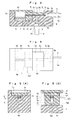
- Fig. 2(A) is an enlarged longitudinal section view of a stationary pipe and a movable pipe shown in Fig. 1;
- Fig. 2(B) is a top view of the stationary pipe and the movable pipe shown in Fig. 1;
- Fig. 2(C) is an end top view of a conveying tube shown in Fig. 1;
- Fig. 3 is an enlarged longitudinal section view of a feed block and a slider shown in Fig. 1;
- Fig. 4 is an enlarged top view of the feed block and the slider shown in Fig. 1;
- Fig. 5(A) is a sectional view taken along a line A-A in Fig. 3;
- Fig. 5(B) is a sectional view taken along a line B-B in Fig. 3;
- Fig. 6 is a view showing a state in which a drive lever of the apparatus shown in Fig. 1 is pushed down;
- Fig. 7 is a view showing a state in which the drive lever of the apparatus shown in Fig. 1 is released from the pushing down and is returned to its original position;
- Figs. 8(A) and 8(B) are views showing an operation in which electronic components in a storage chamber are taken into the stationary pipe by moving up and down the movable pipe;
- Figs. 9 and 10 are views showing an operation of conveying electronic components by sucking air;
- Fig. 11 is a view showing an operation of separating a forefront electronic component from subsequent electronic components by moving the slider forward;
- Fig. 12 is a top face view of Fig. 11;
- Fig. 13 is a view showing an operation of piking up the forefront electronic component by using a suction nozzle;
- Fig. 14(A) is a view showing a modification of a bore of the stationary pipe; and
- Fig. 14(B) is a view showing a modification of a bore of the conveying tube.
-
- Figs. 1 through 13 show an embodiment of an electronic component feeding apparatus according to the present invention. In Figs. 1 through 13,
reference numeral 1 denotes a frame, 2 denotes a storage container, 3 denotes a stationary pipe, 4 denotes a movable pipe, 5 denotes a conveying tube, 6 denotes a feed block, 7 denotes a slider, 8 denotes an air cylinder, 9 denotes an air tube, 10 denotes a driving lever, 11 denotes a link, and 12 denotes a driven lever. In the following descriptions, the left side of Fig. 1 is referred to as "front," the right side of Fig. 1 is referred to as "back or rear," the near side of Fig. 1 is referred to as "left," and the back side of the Fig. 1 is referred to as "right." - The apparatus in Figs. 1 through 13 feeds electronic components P of square pole shape having a dimensional relationship such as length > width = height. The electronic component P includes a chip component such as chip capacitor, chip resistor, chip inductor, and so on; a composite component such as LC filter and so on; and an array component such as capacitor array, inductor array, and so on.
- The
frame 1 is manufactured by punching a plate made of stainless steel or the like into a predetermined shape and forming a plate material on a bending and so on. This frame has a support bracket la for the stationary pipe, a plurality ofsupport brackets 1b for theconveying tube 5, and a plurality ofsupport brackets 1c for theair tube 9, which are formed by local cutting and standing, on one side of theframe 1. Thisframe 1 hasbent parts bent part 1e is provided with a plurality ofpositioning pins 1f to attach the apparatus to other member. If the thickness of theframe 1 is rigid enough to ensure predetermined rigidity, thebent parts - The
storage container 2 comprises a flatstorage container body 2a with an top opening which is formed by a resin molding and aslide lid 2b which freely slides to cover and uncover the top opening of thestorage container body 2a. Aflat storage chamber 2c with an about V-shaped inclined bottom is formed in thestorage container body 2a. Abore 2d circular in cross section, into which themovable pipe 4 is inserted so that it can move up and down, is formed so that thebore 2d runs from the bottom of thestorage container body 2a into the deepest part of the inclined bottom. Using an appropriate number of screws FS, thestorage container 2 is removably attached to theframe 1. - The
stationary pipe 3, made of a metal, a hard resin, etc., has abore 3a rectangular in cross section and an outer shape circular in cross section. As shown in Fig. 2(B), the cross section of thebore 3a is a square which is slightly larger than, and similar to, that of longitudinal end face shape of an electronic component P. Thus, the electronic component P can longitudinally pass through thebore 3a of thestationary pipe 3. As shown in Fig. 2(A), thestationary pipe 3 is inserted into the center of thebore 2d of thestorage container body 2a, its lower end passes through the support bracket la of theframe 1 and is fixed to the the support bracket la. In Fig. 2(A), the upper end of thestationary pipe 3 is slightly below the upper end of thebore 2d. The upper end of thestationary pipe 3 may be almost at the same level as that of thebore 2d or slightly above the upper end of thebore 2d. - The
movable pipe 4, made of a metal, a hard resin, etc., has abore 4a circular in cross section which is slightly larger than the outer shape of thestationary pipe 3 and an outer shape outer shape circular in cross section which is slightly smaller than that of thebore 2d of thestorage container body 2a. A funnel-shaped guide surface 4b is formed at the upper end of themovable pipe 4, and Colors 4c and 4d are formed at the lower end of thepipe 4 and above the side. As shown in Fig. 2(A), themovable pipe 4 is disposed outside thestationary pipe 3, with its upper end inserted into thebore 2d of thestorage container body 2a. A first coil spring S1 is installed below theupper color 4d to prevent overload, and a second coil spring S2 is installed above theupper color 4d to press down themovable pipe 4. The first coil spring S1 produces a larger force than the second coil spring S2. If the force produced by the first coil spring S1 is equal to or smaller than the force produced by the second coil spring S2, however, the movable pipe can move. The bottom of themovable pipe 4 at its lower position (standby position) is in contact with a rubber damper ring LR, installed on thesupport bracket 1a of theframe 1. The upper end of themovable pipe 4 is below the upper end of thestationary pipe 3. That is, when themovable pipe 4 is at the lower position, a circular recess (not indicated by any reference numeral) which is defined by theguide surface 4b of themovable pipe 4, the outer surface of thestationary pipe 3, and thebore 2d is formed above themovable pipe 4. - The
conveying tube 5 is made of a resin such as polypropylene, polyamide system resin, or fluoroplastic, or a metal such as stainless steel. As shown in Fig. 2(C), the cross section of abore 5a of theconveying tube 5 is a square and almost the same as thebore 3a of thestationary pipe 3. Thus, the electronic component P can longitudinally pass through thebore 5a of theconveying tube 5. An outer shape of the conveyingtube 5 is a square similar to the cross section of thebore 5a or circular cross section. Aconnection recess 5b circular in cross section is formed at a start of the conveyingtube 5, thestationary pipe 3 is inserted to and connected with theconnection recess 5b As shown in Fig. 2(A), the conveyingtube 5 is connected its start with the lower end of thestationary pipe 3 so as to align the internal surface of thebore 5a with the internal surface of thebore 3a of thestationary pipe 3 by using an adhesive according to need. The inlet of thebore 5a of the conveyingtube 5 is chamfered or rounded as necessary so that the electronic component P is not caught at the interface between thebore 3a of thestationary pipe 3 to thebore 5a of the conveyingtube 5 when the component conveys from thebore 3a to thebore 5a. In the apparatus in the figure, thebore 5a of the conveyingtube 5 composes a conveying passage for conveying the electronic component P in a alignment state. - As shown in Figs. 3, 4, 5(A), and 5(B), the
feed block 6 has apassage 6a which has almost the same square cross section as thebore 5a of the conveyingtube 5. Aconnection recess 6b square in cross section is formed at the rear end of thepassage 6a, an end of the conveyingtube 5 is inserted to and connected with theconnection recess 6b. The conveyingtube 5 is connected at its end with the thefeed block 6 so as to align the internal surface of thebore 5a with the internal surface of thepassage 6a of thefeed block 6 by using an adhesive according to need. The inlet of thepassage 6a is chamfered or rounded as necessary so that the electronic component P is not caught at the interface between thebore 5a of the conveyingtube 5 to thepassage 6a when the component conveys from thebore 5a to thepassage 6a. Afirst recess 6c which is nearly as wide as ashutter plate 7d described later, and has a depth which is almost equal to a distance between the top surface of thefeed block 6 and the top surface of thepassage 6a is formed above thepassage 6a of thefeed block 6. A front part of thepassage 6a opens through thefirst recess 6c to the outside. Asuction bore 6d circular in cross section which runs from the bottom of thefeed block 6 into that of thepassage 6a is formed at the bottom of thepassage 6a of the feed block G. Thesuction bore 6d is fitted at its lower end with an air tube connector CM. Asecond recess 6e for movably disposing aslider body 7a described later is formed at front side is formed in front of thepassage 6a of thefeed block 6. Thesecond recess 6e is open at the top and on the right and left sides. Acover plate 6f is disposed on thesecond recess 6e of thefeed block 6 to cover the top opening of thesecond recess 6e. The bottom of thecover plate 6f is opposite theshutter plate 7d with a small clearance between these two plates. - As shown in Figs. 3, 4, 5(A), and 5(B), the
slider 7 comprises therectangular slider body 7a, apermanent magnet 7b, astopper plate 7c, and theshutter plate 7d. - The
slider body 7a has at the center of its top a straight groove 7a1 which extends longitudinally. A width of the straight groove 7a1 is slightly smaller than a width of thepassage 6a of thefeed block 6. A magnet installation hole 7a2 which is circular in cross section and has a predetermined depth is formed at the straight groove 7a1 of theslider body 7a. A cylindricalpermanent magnet 7b such as a samarium-cobalt magnet or a ferrite magnet, which has a length almost equal to the depth of the magnet installation hole 7a2, is inserted into the magnet installation hole 7a2 so that the N or S pole of the magnet faces up by using an adhesive according to need. A pin 7a3 which is inserted into anoval hole 12a at the upper end of the drivenlever 12 described later is disposed on the left side of theslider body 7a so that the tip of the pin 7a3 protrudes outside from the left side of thefeed block 6. - The
stopper plate 7c is made of a magnetic material such as iron or the like. Thisstopper plate 7c is nearly as wide as the straight groove 7a1 of theslider body 7a and has a thickness less than a depth of the straight groove 7a1. - The
shutter plate 7d has a width which is slightly smaller than a width of the first recess Gc of thefeed block 6. A straight bump 7d1 which is nearly as wide as the straight groove 7a1 in theslider body 7a and has a height smaller than the depth of the straight groove 7a1 is formed at the center of the bottom of the shutter plate. - The
slider 7 is assembled by inserting thestopper plate 7c into the straight groove 7a1 of theslider body 7a, and then, disposing the theshutter plate 7d on theslider body 7a so as to fit the straight bump 7d1 into the straight groove 7a1. These parts may be combined together using an adhesive, screws, etc.. It is possible to clip thestopper plate 7c by theshutter plate 7d combined with theslider body 7a. After assembling, the bottom of thestopper plate 7c is in contact with the top of thepermanent magnet 7b, so that the rear end of thestopper plate 7c has the N or S pole. The rear end of thestopper plate 7c is beyond theshutter plate 7d. - As shown in Figs. 3, 4, 5(A), and 5(B), the
slider 7 is disposed so that theslider body 7a is in thesecond recess 6e of thefeed block 6 and that the rear of thestopper plate 7c and the rear of the straight bump 7d1 on theshutter plate 7d are in the passage Ga of the feed block G. A third coil spring S3 which is interposed between the front surface of theslider body 7a and that of thesecond recess 6e of thefeed block 6 urges theslider 7, thus pressing the back surface of theslider body 7a against the back surface of the second recess Ge and the rear end of theshutter plate 7d against the back surface of thefirst recess 6c. Thus theshutter plate 7d closes the opening of thepassage 6a of thefeed block 6. As shown in Figs. 3 and 5(A), a clearance which is a part of a suction passage is between the bottom of thepassage 6a and that of thestopper plate 7c. The suction bore 6d and thebore 5a of the conveyingtube 5 communicate through the clearance with each other. In the apparatus in the figure, thestopper plate 7c constitutes a component stopper, and theslider 7 constitutes a displacing device which displaces thestopper plate 7c from a stop position to a removed position therefrom. - The
air cylinder 8, which has arod 8a connected with a piston (not shown), is rotatably supported at itslower end 8b on theframe 1. Theair cylinder 8 has asuction port 8c and anexhaust port 8d which each incorporate a nonreturn valve (not shown). Thesuction port 8c is connected through theair tube 9 with the connector CM at the bottom of thefeed block 6. As shown in Fig. 7, theair cylinder 8 can suck the air through thesuction port 8c by lowering therod 8a from its upper position, and exert an air suction for conveying the electronic componens into thebore 5a of the conveyingtube 5 through the suction passage composed by theair tube 9, thesuction bore 6d, and thepassage 6a. As shown in Fig. 6, theair cylinder 8 can exhaust the air through theexhaust port 8d by lifting therod 8a from its lower position, and discharge the air in theair cylinder 8 through theexhaust port 8d. Besides, the nonreturn valve in theexhaust port 8d closes when the air is sucked, and the nonreturn valve in thesuction port 8c closes when the air is discharged. Thus the air suction can be exerted on the electronic component in thebore 5a of the conveyingtube 5 when the air is sucked, and the positive pressure can be prevented from working in thebore 5a of the conveyingtube 5 when the air is discharged. In the apparatus in the drawing, theair cylinder 8 constitutes a sucking device which conveys the electronic components P in thebore 5a of the conveyingtube 5 using the air suction. - The driving
lever 10 is shaped by a firstvertical plate 10a, ahorizontal plate 10b, and a secondvertical plate 10c which are arranged in that order. The firstvertical plate 10a has aprotrusion 10d extending downward. The drivinglever 10 is rotatably supported nearly at the center of the firstvertical plate 10a on theframe 1 and urged clockwise in the figure by a torsion coil spring S4. A pressed rod 10a1 is provided on the right side at the front end of the firstvertical plate 10a. The pressed rod 10a1 is pressed down by a driving device, not shown, thus causing the drivinglever 10 to rotate counterclockwise (see Fig. 6). Thehorizontal plate 10b is provided with a engaging portion 10b1, that is, a round bore or a U-shaped notch. As shown in Fig. 2(A), the engaging portion 10b1 is between thelower color 4c of themovable pipe 4 and the first coil spring S1. Therod 8a of theair cylinder 8 is rotatably supported on the secondvertical plate 10c. - The rear end of the
link 11 is rotatably connected with the lower end of theprotrusion 10d. The front end of thelink 11 is rotatably connected with the lower end of the drivenlever 12. The drivenlever 12 is rotatably supported nearly at its center on theframe 1. The pin 7a3 of theslider body 7a is inserted into theoval hole 12a at the upper end of the drivenlever 12. - Operation of the apparatus will be described below.
- When the apparatus is used to feed thousands to tens of thousands of the electronic components P, which are stored in a bulk state in the
storage chamber 2c of thestorage container 2, the cycle consisting of the following operations is repeated: (1) using the driving device, not shown, the pressed rod 10a1 of the drivinglever 10 in its standby position is pressed down against urging force produced by the torsion coil spring S4 and the second coil spring S2 (see Fig. 6), and then (2) the pressed rod 10a1 is released to return the drivinglever 10 to its standby position, using urging force produced by the torsion coil spring S4 and the second coil spring S2 (see Fig. 7). - When the
driver lever 10 is rotated counterclockwise through a predetermined angle from the standby position, thehorizontal plate 10b causes themovable pipe 4 to rise from the lower position in Fig. 8(A) to the upper position in Fig. 8(b). When mainly the second coil spring S2 contracts, themovable pipe 4 rises, so that its top slightly enters thestorage chamber 2c. This is because the force produced by the first coil spring S1 is larger than the force produced by the second coil spring S2. As shown in Fig. 8(A), when themovable pipe 4 is in the lower position, several electronic components P are in the circular recess above themovable pipe 4. Thus when themovable pipe 4 rises, these electronic components P are lifted, thus stirring stored electronic components P. As a result, stored electronic components P are taken one by one into the upper end of thebore 3a of the thestationary pipe 3 in a longitudinal direction, directly or under favor of an inclination of theguide surface 4b. When the drivinglever 10 returns to the standby position after it rotates, by returning thehorizontal plate 10b, themovable pipe 4 is returned by the urging force produced by the second coil spring S2 from the upper position in Fig. 8(B) to the lower position in Fig. 8(A). At this time, stored electronic components P are also taken one by one into the upper end of thebore 3a of the thestationary pipe 3 as well as the above-mentioned. - The electronic components P taken into the
bore 3a of thestationary pipe 3 move down through thebore 3a under the gravity, and are taken into thebore 5a of the conveyingtube 5 which is connected to the lower end of thestationary pipe 3. Then the electronic components P taken into thebore 5a of the conveyingtube 5 move down through thebore 5a under the gravity, and are changed its posture from a longitudinal position to a lateral position in a curved segment of the conveyingtube 5. - When the driving
lever 10 returns to the standby position after it rotates, therod 8a of theair cylinder 8 lowers from the upper position to the lower position as shown in Fig. 7. Here through the suction passage composed by theair tube 9, thesuction bore 6d, and thepassage 6a, the air suction for conveying the electronic componens is exerted into thebore 5a of the conveyingtube 5. The electronic components P in thebore 5a of the conveyingtube 5 are moved forward in the alignment state by the air suction as shown in Fig. 9. The electronic components P conveyed in the alignment state by the air suction, stop when the forefront electronic component P against the rear end of thestopper plate 7c as shown in Fig. 10. Following the forefront electronic component P, the subsequent electronic components P are in close contact with each other. The forefront electronic component P is attracted to the rear end of thestopper plate 7c under the action of magnetism, because the rear end of thestopper plate 7c provides the N or S pole as described above. - On the other hand, when the driving
lever 10 is rotated counterclockwise through a predetermined angle from the standby position, as shown in Fig. 6, theprotrusion 10d on the drivinglever 10 displaces, thus pulling back thelink 11, so that the drivenlever 12 rotates counterclockwise through a predetermined angle with a pivot at the center. As shown in Fig. 11, when rotating, the drivenlever 12 causes theslider 7 to move forward a predetermined distance against the urging force produced by the third coil spring S3. Thestopper plate 7c displaces forward from the stop position to the removed position therefrom. The forefront electronic component P, attracted to the rear end of thestopper plate 7c, displaces forward together with thestopper plate 7c, so that the forefront electronic component P is separated from the following electronic components P. Theslider 7 moves forward, thus causing theshutter plate 7d to move away from the back surface of thefirst recess 6c. As a result, the front part of thepassage 6a opens to the outside through thefirst recess 6c, so that the forefront electronic component P is exposed. As shown in Fig. 13, the forefront electronic component P, attracted to the rear end of thestopper plate 7c, is piked up by a suction nozzle AN, which lowers from above the top electronic component. - When the driving
lever 10 is returned to the standby position after it is rotated, theprotrusion 10d of the drivinglever 10 returns to its original position. This causes thelink 11 and drivenlever 12 to also return to their original positions as shown in Fig. 7, so that theslider 7 returns to its original position under the action of the urging force produced by the third coil spring S3, as shown in Fig. 9. When theslider 7 moves back and forth, thepassage 6a, thestopper plate 7c, which is in the passage, and the straight bump 7d1 on theshutter plate 7d; and thefirst recess 6c and theshutter plate 7d which is in the recess; serve as guides. - According to the aforesaid apparatus, by driving the
air cylinder 8 and exerting the air suction into thebore 5a from the end of the conveyingtube 5, the electronic components P in thebore 5a can be conveyed in the predetermined position in the alignment state, and can be stopped by thestopper plate 7c. That is, by using the apparatus with the conveyingtube 5, theair cylinder 8, and thestopper plate 7c, the electronic components P can be conveyed in the alignment state to the predetermined position. Since this apparatus do not need the belt and the belt drive mechanism of the conventional apparatus, the simple and inexpensive electronic component feeding apparatus can be provided. Moreover, since the conveying passage is composed of thetube 5, a plurality of members do not need to be combined to form the conveying passage. This also helps provide the inexpensive electronic component feeding apparatus. - Further, according to the aforesaid apparatus, by displacing the
stopper plate 7c from the stop position to the removed position therefrom with use of theslider 7 after conveyed electronic components P are stopped by thestopper plate 7c, the pick up operation of the forefront electronic component P by usie of the suction nozzle AN is easily performed. Since thepermanent magnet 7b is brought into contact with thestopper plate 7c so that the rear end of thestopper plate 7c provides the N or S pole, when the electronic components P conveyed by the air suction are stopped by thestopper plate 7c, the forefront electronic component P can be attracted to thestopper plate 7c to keep the position of the forefront electronic component P. In addition, since the forefront electronic component P attracted to the rear end of thestopper plate 7c can be displaced forward together with thestopper plate 7c and separated from the following electronic components P by displacing thestopper plate 7c from the stop position to the removed position therefrom, when the forefront electronic component P is picked up by use of the suction nozzle AN, the forefront electronic component P can be picked up in a stable position as preventing the forefront electronic component P from interfering with the following electronic components P. - Furthermore, according to the aforesaid apparatus, since the
air cylinder 8 and the drivinglever 10 for activating theair cylinder 8 are installed on theframe 1, there is no need for placing a vacuum pump and plumbing in this vacuum pump, and for preparing a power supply for the vacuum pump and a circuit for controlling air suction. Thus the cost of the apparatus can be reduced. Both because theair cylinder 8 can be operated, by using the drivinglever 10 and because theslider 7 can be operated through thelink 11 and drivenlever 12 which are connected with the drivinglever 10, a sequence of component feed operations can be securely performed by only applying a force to the drivinglever 10. - Further, according to the aforesaid apparatus, since a take-in device, which is intended to take electronic components in the
storage camber 2c into thebore 5a of the conveyingtube 5 one by one in the predetermined position, is composed of thestationary pipe 3 and themovable pipe 4, electronic components P can be sequentially introduced into thebore 5a of the conveyingtube 5. Moreover, because themovable pipe 4 serves to stir electronic components in thestorage chamber 2c and lead them into thebore 3a of thestationary pipe 3 and thebore 5a of the conveyingtube 5, the electronic components P in thestorage chamber 2c can efficiently be introduced into thebore 5a of the conveyingtube 5. - Furthermore, according to the aforesaid apparatus, since the cross section of the
bore 5a of the conveyingtube 5 is similar to the longitudinal end face shape of the electronic component P and slightly larger than the longitudinal end face shape, the apparatus can properly and stably convey electronic components P having the square pole shape in the alignment state without any problem such as an improper position. - By the way, the aforesaid apparatus can convey cylindrical electronic components P in the same way as electronic components having the square pole shape. When the apparatus is used to convey electronic components P' which meet a dimensional relationship such as length > width > height, the
bore 3a' of a stationary pipe 3' should be provided with a rectangular cross section which is similar to the longitudinal end face shape of the electronic component P' and slightly larger than the longitudinal end face shape as shown in Fig. 14(A). In addition, abore 5a' of a conveyingtube 5' should be provided with a rectangular cross section which is almost the same as the cross section of thebore 3a' of the stationary pipe 3' as shown in Fig. 14(B). - Further, the aforesaid apparatus moves the
slider 7 forward when the pressed rod 10a1 of the drivinglever 10 is pushed down, and exerts the air suction through the suction passage into thebore 5a of the conveyingtube 5 when the pressed rod 10a1 returns to its original position. However, an arrangement also achieves the same effects and advantages as described above which exerts the air suction through the suction passage into thebore 5a of the conveyingtube 5 when the pressed rod 10a1 of the drivinglever 10 is pushed down, and moves theslider 7 forward when the pressed rod 10a1 returns to its original position. - The preferred embodiments described herein are illustrative, not restrictive. The scope of the present invention is defined by the accompanying claims. The present invention covers all variations within the scope of the claims.
Claims (20)
- An electronic component feeding apparatus, comprising:a conveying passage (5a) for conveying electronic components (P) having a predetermined shape in a alignment state;a sucking device (8) for exerting an air suction into the conveying passage (5a) from an end of the conveying passage (5a) and conveying the electronic components (P) in the conveying passage (5a);a movable component stopper (7c) for stopping the electronic components (P) conveyed in the alignment state by the air suction; anda displacing device (7) for displacing the component stopper (7c) from a stop position to a removed position therefrom after the electronic components (P) conveyed are stopped by the component stopper (7c).
- The electronic component feeding apparatus according to claim 1, wherein
the sucking device (8) is installed on an apparatus frame (1), the apparatus frame (1) is provided with a lever mechanism (10) for operating the sucking device (8). - The electronic component feeding apparatus according to claim 2, wherein
the sucking device (8) includes an air cylinder (8) installed on the apparatus frame (1) and a suction passage (6a, 6d and 9) for connecting a suction port (8c) of the air cylinder (8) and the end of the conveying passage (5a). - The electronic component feeding apparatus according to claim 1, whereinthe displacing device (7) includes a movable member (7a) for displacing the component stopper (7c) from the stop position to the removed position, anda lever mechanism (10, 11 and 12) for operating the displacing device (7) is installed on an apparatus frame (1).
- The electronic component feeding apparatus according to claim 4, wherein
the component stopper (7c) includes an adsorbent (7b) for attracting a forefront electronic component (P) of the electronic components (P) stopped by the component stopper (7c). - The electronic component feeding apparatus according to claim 5, wherein
the adsorbent (7b) is a permanent magnet (7b) , the forefront electronic component (P) is attracted to the component stopper (7c) by magnetic force of the permanent magnet (7b). - The electronic component feeding apparatus according to claim 1, further comprising:a storage container (2) for storing electronic components (P) having the predetermined shape in a bulk state; anda take-in device (3 and 4) for taking electronic components (P) one by one into a start of the conveying passage (5a).
- The electronic component feeding apparatus according to claim 7, whereinthe take-in device (3 and 4) includes a movable member (4) for stirring the electronic components (P) in the storage container (2) and leading the electronic components (P) to the start of the conveying passage (5a), anda lever mechanism (10) for operating the the take-in device (3 and 4) is installed on an apparatus frame (1).
- The electronic component feeding apparatus according to claim 1, wherein
the conveying passage (5a) is composed of a tube (5) having a bore (5a) whose cross section allows the electronic components (P) to pass through the bore (5a) in a predetermined direction. - The electronic component feeding apparatus according to claim 9, wherein
the cross section of the bore (5a) of the tube (5) is similar to a longitudinal end face shape of an electronic component (P) and slightly larger than the longitudinal end face shape. - The electronic component feeding apparatus according to claim 9, wherein
the tube (5) is made of a resin. - The electronic component feeding apparatus according to claim 9, wherein
the tube (5) is made of a metal. - An electronic component feeding apparatus, comprising:wherein the conveying passage (5a) is composed of a tube (5) having a bore (5a) whose cross section allows the electronic components (P) to pass through the bore (5a) in a predetermined direction.a conveying passage (5a) for conveying electronic components (P) having a predetermined shape in a alignment state;a sucking device (8) for exerting a air suction into the conveying passage (5a) from an end of the conveying passage (5a) and conveying the electronic components (P) in the conveying passage(5a); anda movable component stopper (7c) for stopping the electronic components (P) conveyed in the alignment state by the air suction;
- The electronic component feeding apparatus according to claim 13, wherein
the cross section of the bore (5a) of the tube (5) is similar to a longitudinal end face shape of a electronic component (P) and slightly larger than the longitudinal end face shape. - The electronic component feeding apparatus according to claim 13, wherein
the tube (5) is made of a resin. - The electronic component feeding apparatus according to claim 13, wherein
the tube (5) is made of a metal. - The electronic component feeding apparatus according to claim 13, wherein
the sucking device (8) is installed on an apparatus frame (1), the apparatus frame (1) is provided with a lever mechanism (10) for operating the sucking device (8). - The electronic component feeding apparatus according to claim 17, wherein
the sucking device (8) includes an air cylinder (8) installed on the apparatus frame (1) and a suction passage (6a, 6d and 9) for connecting a suction port (8c) of the air cylinder (8) and the end of the conveying passage (5a). - The electronic component feeding apparatus according to claim 13, further comprising:a storage container (2) for storing electronic components (P) having the predetermined shape in a bulk state; anda take-in device (3 and 4) for taking electronic components (P) one by one into a start of the conveying passage (5a).
- The electronic component feeding apparatus according to claim 19, whereinthe take-in device (3 and 4) includes a movable member (4) for stirring the electronic components (P) in the storage container (2) and leading the electronic components (P) to the start of the conveying passage (5a), anda lever mechanism (10) for operating the the take-in device (3 and 4) is installed on an apparatus frame (1).
Applications Claiming Priority (2)
| Application Number | Priority Date | Filing Date | Title |
|---|---|---|---|
| JP36785899A JP3520008B2 (en) | 1999-12-24 | 1999-12-24 | Electronic component supply device |
| JP36785899 | 1999-12-24 |
Publications (1)
| Publication Number | Publication Date |
|---|---|
| EP1111983A1 true EP1111983A1 (en) | 2001-06-27 |
Family
ID=18490382
Family Applications (1)
| Application Number | Title | Priority Date | Filing Date |
|---|---|---|---|
| EP00128186A Withdrawn EP1111983A1 (en) | 1999-12-24 | 2000-12-21 | Electronic component feeding apparatus |
Country Status (3)
| Country | Link |
|---|---|
| US (1) | US6443669B2 (en) |
| EP (1) | EP1111983A1 (en) |
| JP (1) | JP3520008B2 (en) |
Families Citing this family (26)
| Publication number | Priority date | Publication date | Assignee | Title |
|---|---|---|---|---|
| US6752291B2 (en) * | 2001-03-29 | 2004-06-22 | Taiyo Yuden Co., Ltd. | Component feeding method, component feeding apparatus, and component feeding unit |
| TW491094U (en) * | 2001-09-28 | 2002-06-11 | Ind Tech Res Inst | Material selection device for micro-workpiece |
| FR2845978B1 (en) * | 2002-10-21 | 2005-07-22 | F2 C2 System | DEVICE FOR DISTRIBUTING WORKPIECES, IN PARTICULAR RIVETS, DELIVERED OUT OF A STORAGE MEANS SUCH AS A VIBRANT BOWL, ITS WORKING PROCESS AND ADAPTIVE VIBRANT BOWL |
| DE10300878B4 (en) * | 2003-01-10 | 2006-04-06 | Richard Bergner Verbindungstechnik Gmbh & Co. Kg | Apparatus and method for feeding a bolt-shaped element to a processing unit |
| ITBO20030491A1 (en) * | 2003-08-08 | 2005-02-09 | Gd Spa | SUPPLY UNIT FOR FILTERS TO A FILTER MACHINE |
| JPWO2005072042A1 (en) * | 2004-01-26 | 2007-09-06 | ドーヴァー テクノロジーズ インターナショナル インコーポレイテッド | Electronic component automatic placement device and parts inventory management device |
| JP2006100484A (en) * | 2004-09-29 | 2006-04-13 | Taiyo Yuden Co Ltd | Component supply apparatus |
| US7678107B2 (en) * | 2005-03-10 | 2010-03-16 | Boston Scientific Scimed, Inc. | Medical needles and electrodes with improved bending stiffness |
| DE102005018651A1 (en) * | 2005-04-21 | 2006-10-26 | Uhlmann Pac-Systeme Gmbh & Co Kg | Device for orientation and onward transport of bulk material |
| US8096100B2 (en) * | 2005-08-24 | 2012-01-17 | Greenwald Technologies Llc | Systems and methods for packaging solid pharmaceutical and/or nutraceutical products and automatically arranging the solid pharmaceutical and nutraceutical products in a linear transmission system |
| CN101646551B (en) * | 2007-03-27 | 2013-06-12 | 诺瓦提斯公司 | Method and device for transporting a molded object |
| FR2926070B1 (en) * | 2008-01-07 | 2009-12-18 | Eris | DEVICE FOR STORING AND DISTRIBUTING SMALL PARTS SUCH AS RIVETS. |
| DE102012212502B4 (en) * | 2012-04-16 | 2016-01-14 | Magna Steyr Fahrzeugtechnik Ag & Co Kg | Nietweiche for more than two different types of loose rivets |
| CN104724481B (en) * | 2013-12-20 | 2017-07-18 | 深圳富泰宏精密工业有限公司 | Sorting mechanism |
| GB201405340D0 (en) * | 2014-03-25 | 2014-05-07 | British American Tobacco Co | Feed Unit |
| GB201405337D0 (en) | 2014-03-25 | 2014-05-07 | British American Tobacco Co | Feed unit |
| GB201405341D0 (en) | 2014-03-25 | 2014-05-07 | British American Tobacco Co | Feed unit |
| GB201405342D0 (en) | 2014-03-25 | 2014-05-07 | British American Tobacco Co | Feed unit |
| ES2651102T3 (en) * | 2014-12-22 | 2018-01-24 | Kuka Systems Aerospace | Feeder mechanism to provide mechanical fasteners |
| US9459183B1 (en) * | 2015-01-15 | 2016-10-04 | Bruce D. Schnakenberg | System for the collection and disposal of grain samples |
| CN107406202B (en) * | 2015-03-06 | 2019-12-03 | 仓敷纺绩株式会社 | item supply device |
| JP5840815B1 (en) * | 2015-07-07 | 2016-01-06 | 株式会社電元社製作所 | Nut feeder |
| KR20180098537A (en) * | 2015-12-28 | 2018-09-04 | 구라시키 보세키 가부시키가이샤 | Method and apparatus for supplying goods |
| US10615292B2 (en) * | 2018-03-27 | 2020-04-07 | Hong Kong Applied Science And Technology Research Institute Co., Ltd. | High voltage silicon carbide Schottky diode flip chip array |
| JP7486618B2 (en) * | 2021-01-29 | 2024-05-17 | 株式会社Fuji | Bulk feeders and component placement machines |
| CN113747782B (en) * | 2021-09-06 | 2023-03-03 | 常州冯卡斯登智能科技有限公司 | Automatic feeding device for chip mounter |
Citations (4)
| Publication number | Priority date | Publication date | Assignee | Title |
|---|---|---|---|---|
| JPH02160432A (en) * | 1988-12-15 | 1990-06-20 | Toshiba Corp | Feeding device for part |
| GB2244482A (en) * | 1990-05-31 | 1991-12-04 | Taiyo Yuden Kk | Parts dispensing device |
| JPH0856097A (en) * | 1994-08-09 | 1996-02-27 | Matsushita Electric Ind Co Ltd | Chip component feeder |
| US5525023A (en) * | 1992-12-10 | 1996-06-11 | Matsushita Electric Industrial Co., Ltd. | Chip component supply apparatus |
Family Cites Families (9)
| Publication number | Priority date | Publication date | Assignee | Title |
|---|---|---|---|---|
| AT368104B (en) * | 1979-06-25 | 1982-09-10 | Sticht Walter | AIR TRANSPORT SYSTEM, ESPECIALLY FOR ASSEMBLY PARTS |
| JP3453809B2 (en) | 1992-12-10 | 2003-10-06 | 松下電器産業株式会社 | Chip component supply device and chip component supply method |
| EP0683625B1 (en) * | 1994-05-18 | 1998-07-22 | Taiyo Yuden Co., Ltd. | Apparatus for supplying chip parts and method for same |
| KR100279368B1 (en) * | 1996-11-15 | 2001-01-15 | 가와다 미쓰구 | Chip component feeding apparatus and attracting plate for use in same |
| JP3579234B2 (en) * | 1997-12-09 | 2004-10-20 | 太陽誘電株式会社 | Chip component supply device |
| JP3956036B2 (en) * | 1997-12-22 | 2007-08-08 | 井関農機株式会社 | Rice transplanter |
| JP3814400B2 (en) * | 1998-01-05 | 2006-08-30 | 松下電器産業株式会社 | Bulk feeder |
| JP4141004B2 (en) * | 1998-03-04 | 2008-08-27 | 太陽誘電株式会社 | Chip component supply device |
| JP4275255B2 (en) * | 1999-06-25 | 2009-06-10 | 富士機械製造株式会社 | Alignment feeder |
-
1999
- 1999-12-24 JP JP36785899A patent/JP3520008B2/en not_active Expired - Fee Related
-
2000
- 2000-12-21 EP EP00128186A patent/EP1111983A1/en not_active Withdrawn
- 2000-12-22 US US09/742,223 patent/US6443669B2/en not_active Expired - Fee Related
Patent Citations (4)
| Publication number | Priority date | Publication date | Assignee | Title |
|---|---|---|---|---|
| JPH02160432A (en) * | 1988-12-15 | 1990-06-20 | Toshiba Corp | Feeding device for part |
| GB2244482A (en) * | 1990-05-31 | 1991-12-04 | Taiyo Yuden Kk | Parts dispensing device |
| US5525023A (en) * | 1992-12-10 | 1996-06-11 | Matsushita Electric Industrial Co., Ltd. | Chip component supply apparatus |
| JPH0856097A (en) * | 1994-08-09 | 1996-02-27 | Matsushita Electric Ind Co Ltd | Chip component feeder |
Also Published As
| Publication number | Publication date |
|---|---|
| US20010005471A1 (en) | 2001-06-28 |
| JP3520008B2 (en) | 2004-04-19 |
| US6443669B2 (en) | 2002-09-03 |
| JP2001185897A (en) | 2001-07-06 |
Similar Documents
| Publication | Publication Date | Title |
|---|---|---|
| US6443669B2 (en) | Electronic component feeding apparatus | |
| US7331442B2 (en) | Chip components feeding apparatus | |
| WO2018003922A1 (en) | Automatic continuous image engraving device | |
| US6752291B2 (en) | Component feeding method, component feeding apparatus, and component feeding unit | |
| JPH0864992A (en) | Chip component feeder | |
| US6471094B2 (en) | Electronic component feeding apparatus | |
| CN210226103U (en) | Component conveying device | |
| JPH03295300A (en) | Electronic component automatic feeder | |
| JPH0752072Y2 (en) | Electronic component storage pack | |
| JPH1149337A (en) | Chip part feeding device | |
| CN209919268U (en) | Jump ring assembly quality | |
| JP3642071B2 (en) | Chip component supply device | |
| JP3817104B2 (en) | Electronic component feeder | |
| JP3785325B2 (en) | Electronic component transfer method and transfer device | |
| CN215701347U (en) | Magnetic loading device | |
| CN119789410B (en) | Electronic component plug-in device | |
| CN224242010U (en) | Material distributing device | |
| JP4171291B2 (en) | Parts supply device | |
| JP3862465B2 (en) | Electronic component feeder | |
| JPH02222600A (en) | Automatic feeder of electronic component | |
| JP2001278437A (en) | Part supply device | |
| JP2575911Y2 (en) | Chip-shaped circuit component mounting device | |
| JP3586389B2 (en) | Parts feeder | |
| KR20030037368A (en) | Continuous riveter | |
| JP2000280126A (en) | Part feeder |
Legal Events
| Date | Code | Title | Description |
|---|---|---|---|
| PUAI | Public reference made under article 153(3) epc to a published international application that has entered the european phase |
Free format text: ORIGINAL CODE: 0009012 |
|
| AK | Designated contracting states |
Kind code of ref document: A1 Designated state(s): AT BE CH CY DE DK ES FI FR GB GR IE IT LI LU MC NL PT SE TR |
|
| AX | Request for extension of the european patent |
Free format text: AL;LT;LV;MK;RO;SI |
|
| AKX | Designation fees paid | ||
| REG | Reference to a national code |
Ref country code: DE Ref legal event code: 8566 |
|
| STAA | Information on the status of an ep patent application or granted ep patent |
Free format text: STATUS: THE APPLICATION IS DEEMED TO BE WITHDRAWN |
|
| 18D | Application deemed to be withdrawn |
Effective date: 20011228 |