EP1111473A2 - Lithographischer Apparat mit Vakuumkammer und interferometrischem Ausrichtungssystem - Google Patents
Lithographischer Apparat mit Vakuumkammer und interferometrischem Ausrichtungssystem Download PDFInfo
- Publication number
- EP1111473A2 EP1111473A2 EP00311544A EP00311544A EP1111473A2 EP 1111473 A2 EP1111473 A2 EP 1111473A2 EP 00311544 A EP00311544 A EP 00311544A EP 00311544 A EP00311544 A EP 00311544A EP 1111473 A2 EP1111473 A2 EP 1111473A2
- Authority
- EP
- European Patent Office
- Prior art keywords
- constructed
- radiation
- substrate
- alignment system
- measurement
- Prior art date
- Legal status (The legal status is an assumption and is not a legal conclusion. Google has not performed a legal analysis and makes no representation as to the accuracy of the status listed.)
- Withdrawn
Links
- 238000005259 measurement Methods 0.000 claims abstract description 30
- 238000003384 imaging method Methods 0.000 claims abstract description 16
- 238000005286 illumination Methods 0.000 claims abstract description 14
- 239000013307 optical fiber Substances 0.000 claims abstract description 10
- 239000000758 substrate Substances 0.000 claims description 55
- 230000005855 radiation Effects 0.000 claims description 44
- 239000000835 fiber Substances 0.000 claims description 22
- 238000000059 patterning Methods 0.000 claims description 19
- 230000003287 optical effect Effects 0.000 claims description 18
- 238000000034 method Methods 0.000 claims description 10
- 238000004519 manufacturing process Methods 0.000 claims description 9
- 239000000463 material Substances 0.000 claims description 8
- 230000010287 polarization Effects 0.000 claims description 8
- 230000001678 irradiating effect Effects 0.000 claims description 2
- 238000001914 filtration Methods 0.000 claims 1
- 238000000926 separation method Methods 0.000 abstract description 2
- 238000001514 detection method Methods 0.000 description 11
- 239000010410 layer Substances 0.000 description 11
- 239000003550 marker Substances 0.000 description 10
- 238000006073 displacement reaction Methods 0.000 description 4
- 238000010586 diagram Methods 0.000 description 3
- 238000010894 electron beam technology Methods 0.000 description 3
- 239000011521 glass Substances 0.000 description 3
- 238000001459 lithography Methods 0.000 description 3
- 230000033001 locomotion Effects 0.000 description 3
- 239000002245 particle Substances 0.000 description 3
- 210000001747 pupil Anatomy 0.000 description 3
- XUIMIQQOPSSXEZ-UHFFFAOYSA-N Silicon Chemical compound [Si] XUIMIQQOPSSXEZ-UHFFFAOYSA-N 0.000 description 2
- 239000006094 Zerodur Substances 0.000 description 2
- 239000011248 coating agent Substances 0.000 description 2
- 238000000576 coating method Methods 0.000 description 2
- 230000004907 flux Effects 0.000 description 2
- 238000010884 ion-beam technique Methods 0.000 description 2
- 229910052745 lead Inorganic materials 0.000 description 2
- 230000010363 phase shift Effects 0.000 description 2
- 239000004065 semiconductor Substances 0.000 description 2
- 238000007493 shaping process Methods 0.000 description 2
- 229910052710 silicon Inorganic materials 0.000 description 2
- 239000010703 silicon Substances 0.000 description 2
- 230000000007 visual effect Effects 0.000 description 2
- OKTJSMMVPCPJKN-UHFFFAOYSA-N Carbon Chemical group [C] OKTJSMMVPCPJKN-UHFFFAOYSA-N 0.000 description 1
- 239000004215 Carbon black (E152) Substances 0.000 description 1
- VYZAMTAEIAYCRO-UHFFFAOYSA-N Chromium Chemical compound [Cr] VYZAMTAEIAYCRO-UHFFFAOYSA-N 0.000 description 1
- 241000206607 Porphyra umbilicalis Species 0.000 description 1
- 229910052774 Proactinium Inorganic materials 0.000 description 1
- BQCADISMDOOEFD-UHFFFAOYSA-N Silver Chemical compound [Ag] BQCADISMDOOEFD-UHFFFAOYSA-N 0.000 description 1
- 238000010521 absorption reaction Methods 0.000 description 1
- 230000004075 alteration Effects 0.000 description 1
- 238000003491 array Methods 0.000 description 1
- 230000002238 attenuated effect Effects 0.000 description 1
- 238000005452 bending Methods 0.000 description 1
- 230000005540 biological transmission Effects 0.000 description 1
- 239000005388 borosilicate glass Substances 0.000 description 1
- 229910052799 carbon Inorganic materials 0.000 description 1
- 229910002091 carbon monoxide Inorganic materials 0.000 description 1
- 239000004568 cement Substances 0.000 description 1
- 239000000919 ceramic Substances 0.000 description 1
- 229910052804 chromium Inorganic materials 0.000 description 1
- 239000011651 chromium Substances 0.000 description 1
- 230000001427 coherent effect Effects 0.000 description 1
- 238000010276 construction Methods 0.000 description 1
- 239000000356 contaminant Substances 0.000 description 1
- 238000000151 deposition Methods 0.000 description 1
- 230000008021 deposition Effects 0.000 description 1
- 238000013461 design Methods 0.000 description 1
- 238000011161 development Methods 0.000 description 1
- 238000009826 distribution Methods 0.000 description 1
- 230000005670 electromagnetic radiation Effects 0.000 description 1
- 238000005530 etching Methods 0.000 description 1
- 239000005308 flint glass Substances 0.000 description 1
- 230000006870 function Effects 0.000 description 1
- 239000007789 gas Substances 0.000 description 1
- 229930195733 hydrocarbon Natural products 0.000 description 1
- 150000002430 hydrocarbons Chemical class 0.000 description 1
- 238000007689 inspection Methods 0.000 description 1
- 238000005468 ion implantation Methods 0.000 description 1
- 150000002500 ions Chemical class 0.000 description 1
- 239000002346 layers by function Substances 0.000 description 1
- 239000004973 liquid crystal related substance Substances 0.000 description 1
- 230000005381 magnetic domain Effects 0.000 description 1
- 238000012423 maintenance Methods 0.000 description 1
- 239000011159 matrix material Substances 0.000 description 1
- 230000015654 memory Effects 0.000 description 1
- 238000001465 metallisation Methods 0.000 description 1
- 238000010943 off-gassing Methods 0.000 description 1
- 230000003647 oxidation Effects 0.000 description 1
- 238000007254 oxidation reaction Methods 0.000 description 1
- 229910052763 palladium Inorganic materials 0.000 description 1
- 238000005498 polishing Methods 0.000 description 1
- 230000037452 priming Effects 0.000 description 1
- 238000012545 processing Methods 0.000 description 1
- 239000010453 quartz Substances 0.000 description 1
- VYPSYNLAJGMNEJ-UHFFFAOYSA-N silicon dioxide Inorganic materials O=[Si]=O VYPSYNLAJGMNEJ-UHFFFAOYSA-N 0.000 description 1
- 229910052709 silver Inorganic materials 0.000 description 1
- 239000004332 silver Substances 0.000 description 1
- 125000006850 spacer group Chemical group 0.000 description 1
- 238000003860 storage Methods 0.000 description 1
- 239000010409 thin film Substances 0.000 description 1
- 238000013519 translation Methods 0.000 description 1
Images


Classifications
-
- G—PHYSICS
- G03—PHOTOGRAPHY; CINEMATOGRAPHY; ANALOGOUS TECHNIQUES USING WAVES OTHER THAN OPTICAL WAVES; ELECTROGRAPHY; HOLOGRAPHY
- G03F—PHOTOMECHANICAL PRODUCTION OF TEXTURED OR PATTERNED SURFACES, e.g. FOR PRINTING, FOR PROCESSING OF SEMICONDUCTOR DEVICES; MATERIALS THEREFOR; ORIGINALS THEREFOR; APPARATUS SPECIALLY ADAPTED THEREFOR
- G03F9/00—Registration or positioning of originals, masks, frames, photographic sheets or textured or patterned surfaces, e.g. automatically
- G03F9/70—Registration or positioning of originals, masks, frames, photographic sheets or textured or patterned surfaces, e.g. automatically for microlithography
- G03F9/7096—Arrangement, mounting, housing, environment, cleaning or maintenance of apparatus
-
- G—PHYSICS
- G03—PHOTOGRAPHY; CINEMATOGRAPHY; ANALOGOUS TECHNIQUES USING WAVES OTHER THAN OPTICAL WAVES; ELECTROGRAPHY; HOLOGRAPHY
- G03F—PHOTOMECHANICAL PRODUCTION OF TEXTURED OR PATTERNED SURFACES, e.g. FOR PRINTING, FOR PROCESSING OF SEMICONDUCTOR DEVICES; MATERIALS THEREFOR; ORIGINALS THEREFOR; APPARATUS SPECIALLY ADAPTED THEREFOR
- G03F9/00—Registration or positioning of originals, masks, frames, photographic sheets or textured or patterned surfaces, e.g. automatically
- G03F9/70—Registration or positioning of originals, masks, frames, photographic sheets or textured or patterned surfaces, e.g. automatically for microlithography
- G03F9/7049—Technique, e.g. interferometric
Definitions
- the present invention relates to interferometer-based alignment and position measurement systems. More particularly, the invention relates to such systems used in lithographic projection apparatus comprising:
- patterning means should be broadly interpreted as referring to means that can be used to endow an incoming radiation beam with a patterned cross-section, corresponding to a pattern that is to be created in a target portion of the substrate; the term “light valve” has also been used in this context.
- the said pattern will correspond to a particular functional layer in a device being created in the target portion, such as an integrated circuit or other device (see below). Examples of such patterning means include:
- the projection system may hereinafter be referred to as the "lens"; however, this term should be broadly interpreted as encompassing various types of projection system, including refractive optics, reflective optics, and catadioptric systems, for example.
- the illumination system may also include components operating according to any of these design types for directing, shaping or controlling the projection beam of radiation, and such components may also be referred to below, collectively or singularly, as a "lens".
- the lithographic apparatus may be of a type having two or more substrate tables (and/or two or more mask tables).
- twin stage lithographic apparatus are described, for example, in US 5,969,441 and US Serial No. 09/180,011, filed 27 February, 1998 (WO 98/40791), incorporated herein by reference.
- Lithographic projection apparatus can be used, for example, in the manufacture of integrated circuits (ICs).
- the patterning means may generate a circuit pattern corresponding to an individual layer of the IC, and this pattern can be imaged onto a target portion (comprising one or more dies) on a substrate (silicon wafer) that has been coated with a layer of radiation-sensitive material (resist).
- a target portion comprising one or more dies
- a substrate silicon wafer
- a layer of radiation-sensitive material resist
- a single wafer will contain a whole network of adjacent target portions that are successively irradiated via the projection system, one at a time.
- employing patterning by a mask on a mask table a distinction can be made between two different types of machine.
- each target portion is irradiated by exposing the entire mask pattern onto the target portion in one go; such an apparatus is commonly referred to as a wafer stepper.
- a step-and-scan apparatus each target portion is irradiated by progressively scanning the mask pattern under the projection beam in a given reference direction (the "scanning" direction) while synchronously scanning the substrate table parallel or anti-parallel to this direction; since, in general, the projection system will have a magnification factor M (generally ⁇ 1), the speed V at which the substrate table is scanned will be a factor M times that at which the mask table is scanned.
- M magnification factor
- EUV Extreme Ultraviolet
- electron beams ion beams
- other charged particle fluxes ion beams
- EUV Extreme Ultraviolet
- These types of radiation beam share the requirement that the beam path, including the mask, substrate and optical components, be kept in a high vacuum. This is to prevent absorption and/or scattering of the beam and a total pressure of less than about 10 -6 millibar is necessary.
- Optical elements for EUV radiation can be spoiled by the deposition of carbon layers on their surface which imposes the additional requirement that hydrocarbon partial pressures must be kept below 10 -8 or 10 -9 millibar.
- the substrate (wafer) that is being exposed must be positioned to extremely high accuracy relative to the mask (reticle).
- a wafer may undergo 20 or 30 exposures during the manufacture and it is essential that the various images are properly aligned, even if different lithography apparatus are used for different exposures.
- the overlay accuracy requirements only increase with reduced feature size and shorter wavelength radiation.
- An object of the present invention is to provide an alignment and/or position measuring system capable of measuring the position of an object in vacuum with high accuracy, e.g. for use in a lithographic projection apparatus.
- a lithographic projection apparatus comprising:
- the present invention avoids difficulties in making the active part of the alignment system vacuum compatible and reduces heat and vibration generation in the vacuum system, which may disturb the exposure and cause positioning uncertainties.
- the active and passive parts of the system are coupled together by optical fibers.
- the alignment system may be an interferometer system for detecting the position of a measurement grating (wafer mark) relative to a reference grating.
- Such a system may image at least two orders of radiation diffracted by the measurement grating onto the reference grating and may comprise beam splitting means to separate radiation diffracted by the reference grating and deriving from one order diffracted by the measurement grating from diffracted radiation deriving from other orders diffracted by the measurement grating.
- a device manufacturing method comprising the steps of:
- a pattern in a mask is imaged onto a substrate which is at least partially covered by a laver of radiation-sensitive material (resist).
- the substrate Prior to this imaging step, the substrate may undergo various procedures, such as priming, resist coating and a soft bake. After exposure, the substrate may be subjected to other procedures, such as a post-exposure bake (PEB), development, a hard bake and measurement/inspection of the imaged features.
- PEB post-exposure bake
- This array of procedures is used as a basis to pattern an individual layer of a device, e.g. an IC.
- Such a patterned layer may then undergo various processes such as etching, ion-implantation (doping), metallization, oxidation, chemo-mechanical polishing, etc., all intended to finish off an individual layer. If several layers are required, then the whole procedure, or a variant thereof, will have to be repeated for each new layer. Eventually, an array of devices will be present on the substrate (wafer). These devices are then separated from one another by a technique such as dicing or sawing, whence the individual devices can be mounted on a carrier, connected to pins, etc. Further information regarding such processes can be obtained, for example, from the book “Microchip Fabrication: A Practical Guide to Semiconductor Processing", Third Edition, by Peter van Zant, McGraw Hill Publishing Co., 1997, ISBN 0-07-067250-4.
- UV radiation e.g. at a wavelength of 365nm, 248 nm, 193 nm, 157nm or 126nm
- EUV radiation extreme ultraviolet radiation
- X-rays electrons and ions.
- Figure 1 schematically depicts a lithographic projection apparatus according to the invention.
- the apparatus comprises:
- the radiation system comprises a source LA (e . g . a Hg lamp, excimer laser, an undulator provided around the path of an electron beam in a storage ring or synchrotron, a plasma source, or an electron or ion beam source) which produces a beam of radiation.
- a source LA e . g . a Hg lamp, excimer laser, an undulator provided around the path of an electron beam in a storage ring or synchrotron, a plasma source, or an electron or ion beam source
- This beam is passed along various optical components comprised in the illumination system, - e . g . beam shaping optics EX, an integrator IN and a condenser CO ⁇ so that the resultant beam PB has a desired shape and intensity distribution in its cross-section.
- the beam PB subsequently intercepts the mask MA which is held in a mask holder on a mask table MT. Having passed through the mask MA, the beam PB passes through the lens PL, which focuses the beam PB onto a target portion C of the substrate W.
- the substrate table WT can be moved accurately, e . g . so as to position different target portions C in the path of the beam PB.
- the interferometric displacement means IF and the first positioning means can be used to accurately position the mask MA with respect to the path of the beam PB, e . g . after mechanical retrieval of the mask MA from a mask library.
- movement of the object tables MT, WT will be realized with the aid of a long stroke module (course positioning) and a short stroke module (fine positioning), which are not explicitly depicted in Figure 1.
- the depicted apparatus can be used in two different modes:
- a correct alignment may be achieved by aligning one or more markers M 1 , M 2 provided on the mask MA with respect to one or more corresponding reference markers M R provided on wafer table WT, as shown in Figure 2.
- the position of the substrate table with respect to the mask will then lie known.
- Such an alignment may be achieved by using projection (actinic) radiation and the projection system to image the markers M 1 , M 2 onto the reference marker M R .
- the reference marker may take the form of an image sensor provided on the substrate (wafer) table WT. Details of such an image sensor arc not shown in the figures.
- the position of the wafer W with respect to the wafer table WT must be known in order to align the wafer W with respect to the mask MA.
- An additional alignment system 10 which embodies the present invention, is used for this purpose. With the alignment system 10, one or more markers P 1 , P 2 , P, in the form of diffraction gratings provided on the wafer and wafer table will be aligned with respect to a reference marker or grating 13 of the alignment system 10 by moving the wafer table WT. Recording the respective aligned positions with the aid of the interferometric displacement measuring means IF will then yield a position of the wafer with respect to the wafer table.
- the markers P and M R on the wafer table WT are shown in Figure 2 on a common plate, which is mounted on the wafer table.
- An arrangement of this type, in which part or all of the alignment process can be carried out away from the main axis of the machine (the optical axis of the projection system PL), is sometimes referred to as an "off-axis" alignment system.
- the wafer W and the wafer table WT are contained in a vacuum chamber VC that is maintained at a vacuum during operation of the apparatus.
- the alignment system 10 comprises a passive part 10a enclosed in the vacuum chamber and an active part 10b disposed outside the vacuum chamber VC.
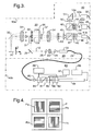
- the optical components of the alignment system 10 are shown in Figure 3.
- the passive part 10a enclosed in the vacuum chamber VC of alignment system 10 comprises three main sections; illumination branch 20, imaging branch 30 and detection branch 40. These branches respectively perform the functions of: collimating and adjusting the measurement beam 12; projecting the measurement beam 12 onto the wafer marker P and imaging the diffracted radiation onto the fixed reference grating 13; and separating the resultant diffraction beams so that they can be converted into electronic signals for use by the control system of the lithography apparatus.
- the active part 10b provided outside the vacuum chamber VC in this embodiment consists of the laser module 80 shown in Figure 3 and photodetectors (not shown) for converting the sub-beams separated by the detection branch into electronic control signals.
- the laser module 80 includes laser 81 which is, for example, a 10mW HeNe laser outputting a beam of wavelength 633 nm.
- the beam is first passed through a safety shutter 82, Faraday isolator 90, modulator 83, polarizing beam splitter 91 and attenuator 84, which is provided for control purposes.
- the safety shutter 82 completely blocks the laser beam when it is not required, and particularly when the apparatus has been opened up, e.g. for maintenance, for safety reasons.
- Faraday isolator 90 prevents unwanted back reflections from any of the optical components in the system reaching the laser 81 and disturbing its operation, e.g. by causing frequency pulling or mode hopping, etc.
- Piezo-electric modulator 83 and polarizing beam splitter 91 are used in a modulation-demodulation detection scheme to enhance the signal to noise ratio of the sensor.
- the beam is coupled into a single-mode polarization-preserving fiber 21, which is optimized for the wavelength of the radiation, via fiber manipulator 85 and is taken into the vacuum chamber.
- the laser module 80 can also conveniently include the laser power supply 86, modulator driver 87 and control electronics 88 in the same package.
- the measurement beam 12 exits the fiber terminator 22 that includes collimating optics to provide a collimated beam.
- the collimated beam is focused at the center of the pupil plane of the imaging branch 30 by a plano-convex lens 23.
- a first plane-plate 24 before plano-convex lens 23 is used to adjust the angle of the measurement beam at the imaging branch pupil and hence the position of the beam at the plane of the wafer. An initial, coarse, adjustment of this can be done by X-Y translation of the fiber optics output.
- a second plane-plate 25 is positioned after the plano-convex lens 23 and used to adjust the position of the measurement beam 12 at the pupil plane and hence its angle of incidence at the plane of the wafer.
- a 90° mirror 26 brings the measurement beam into the imaging branch 30.
- the measurement beam is coupled along the optical axis (Z-axis) using a small mirror 31.
- Mirror 31 is conveniently mounted in the center of first order-diaphragm 32, whose purpose is described below.
- the use of air-spaced doublets is preferred since optical cements, such as would be found in a simpler achromatic doublet, mav not be vacuum compatible.
- the accuracy of the spacing of the singlets in the doublet is a major determinant of system performance and is assured by using accurately machined ceramic spacer balls (the error in the radius being ⁇ 1 ⁇ m); this guarantees high mounting accuracy (i.e. spacing distance), vacuum compatibility and thermal stability.
- SF1 is a heavy flint glass having a refractive index of about 1.7 which allows the lenses to have a suitable focal length without an excessive radius of curvature.
- the symmetry of the system reduces any aberrations caused by uncertainty in the refractive index of the SF1 glass. To this end the lenses should all be made from the same batch of glass.
- First order-diaphragm 32, bearing mirror 31 is mounted between first and second doublets 33, 34 so that the measurement beam is collimated on wafer marker P on wafer W by first doublet 33.
- Front mirror 35 is provided so that the alignment system can be positioned in a convenient location and the measurement beam 12 is incident normally on the reference mark P.
- Front mirror 35 may be a Zerodur (TM) substrate (for thermal stability) with metallic coating for efficient reflection of the S-polarized illumination beam at 45° angle of incidence as well as the returning diffraction orders at angles of ⁇ about 54°.
- the mirror may be mounted on a Zerodur (TM) frame for additional thermal stability.
- the illumination beam is reflected and diffracted into diffraction orders at specific angles in the XZ and YZ planes.
- the first doublet 33 has an aperture sized to select the diffraction orders up to and including the fourth and focuses the collimated orders in its back focal plane.
- the parallel orders pass through first order-diaphragm 32 that includes apertures which pass only the first 12a and fourth 12b diffraction orders.
- a linear polarizer 36 is used to clean-up the polarization of both orders 12a, 12b, since this may have become slightly elliptical on reflection by front mirror 35, after which only the first order 12a is passed through a half-wave plate 37 so that the linear polarization states of the two orders are 90° apart.
- Polarizer 36 may be formed of borosilicate glass with aligned silver particles, which is a vacuum compatible component, and effectively reduces cross-talk between the two beams.
- Half-wave plate 37 may be a quartz plate of appropriate thickness for the single wavelength of the measurement beam 12.
- Second lens doublet 34 images the first and fourth orders 12a, 12b onto its back focal plane in which the fixed reference grating 13 is positioned.
- the reference pattern of reference grating 13 is a hard copy formed of chromium on glass of the aerial image of the plus and minus sub-beams of the first-order beams from the wafer marker P.
- the total image of the wafer marker at the reference pattern will move correspondingly.
- the transmitted light is then captured and measured by the detection branch 40.
- the light in the first-order beam 12a will be diffracted into diffraction orders forming beams which are spatially well-separated from the beams formed of the diffraction orders into which the light in the fourth-order beam 12b is diffracted.
- Diffraction orders of the plus and minus sub-beams of the first-order beam 12a will overlap as will diffraction orders of the plus and minus sub-beams of the fourth order beam 12b.
- the diffraction components deriving from the first-order beam 12a and those deriving from the fourth-order beam 12b will have linear polarization states differing by 90°, since the linear polarization states of the first-order beam 12a and the fourth-order beam 12b are 90° apart.
- diffraction components deriving from the first-order beam 12a and those deriving from the fourth-order beam 12b are separated into first and second signal sub-beams 12c, 12d respectively by first and second polarizing beam splitters 41, 42 and further order-diaphragms 43, 44.
- Such components as pass through the second beam splitter 42 are projected by fourth lens 50 and a 90° bending prism 51 onto a coherent fiber bundle 52 mounted in terminator 52a.
- the resulting image beam, third signal sub-beam 12e, carries an image of the reference pattern 13.
- the first, second and third signal sub-beams 12c, 12d, 12e are taken out of the vacuum chamber by their respective fiber bundles 47, 49, 52.
- the first and second signal sub-beams are passed to detectors of known type to make an accurate measurement of the reference mark position in a known alignment scan process.
- the third signal sub-beam is taken to a CCD camera to provide a visual indication of the alignment to an operator of the apparatus.
- Figure 4 is an aerial view of the wafer marker P showing its four quadrants Pa, Pb, Pc, Pd. These arc arranged such that two diagonally opposite quadrants Pa, Pc have grating lines parallel to the X-axis whilst the other two quadrants Pb, Pd have grating lines parallel to the Y-axis.
- FIG. 5 A second embodiment of the invention is illustrated in Figures 5 and 6.
- This embodiment shares a number of components with the first embodiment and parts not specifically described below are similar to the corresponding parts of the first embodiment.
- the laser module 80, illumination branch 20 and imaging branch 30 in the second embodiment are essentially the same as those of the first embodiment.
- the major difference between the two embodiments is that the detection branch 70 is located outside the vacuum chamber VC.
- the light passing through the reference grating 13, which represents a combined image of gratings P and 13, is collected by a fiber taper 60 which magnifies the image and delivers it into fiber bundle 61 to be taken out of the vacuum chamber to detection branch 70, shown in Figure 6.
- the fiber ends are tapered and packed closer together so that the image grows as it is transmitted down the bundle.
- Fiber bundle 61 terminates at a terminator 62 and emits the combined image signal through window 63 in the wall of the vacuum chamber VC.
- the combined image is projected by lenses 71, 72 onto a photodiode detector 73 of known type, including a pre-amp, which provides the electronic alignment signal for the apparatus control systems.
- the photodiode detector 73 has four quadrants to separately detect the four gratings of the wafer and reference gratings P, 13.
- a portion of the combined image signal is diverted by a polarizing beam splitter 74 positioned between lenses 71, 72.
- Figure 6 also shows how the light from laser module 80 is taken via fiber 89 to window 64 in vacuum chamber wall thorough which it is transmitted to fiber 21 leading to the illumination branch in the vacuum chamber.
- the first-order and fourth-order beams can be separated and separately detected outside the vacuum chamber VC for improved alignment accuracy, provided that fiber 61 is polarization preserving.
Landscapes
- Physics & Mathematics (AREA)
- General Physics & Mathematics (AREA)
- Length Measuring Devices By Optical Means (AREA)
- Exposure And Positioning Against Photoresist Photosensitive Materials (AREA)
Priority Applications (1)
| Application Number | Priority Date | Filing Date | Title |
|---|---|---|---|
| EP00311544A EP1111473A3 (de) | 1999-12-23 | 2000-12-21 | Lithographischer Apparat mit Vakuumkammer und interferometrischem Ausrichtungssystem |
Applications Claiming Priority (3)
| Application Number | Priority Date | Filing Date | Title |
|---|---|---|---|
| EP99310519 | 1999-12-23 | ||
| EP99310519 | 1999-12-23 | ||
| EP00311544A EP1111473A3 (de) | 1999-12-23 | 2000-12-21 | Lithographischer Apparat mit Vakuumkammer und interferometrischem Ausrichtungssystem |
Publications (2)
| Publication Number | Publication Date |
|---|---|
| EP1111473A2 true EP1111473A2 (de) | 2001-06-27 |
| EP1111473A3 EP1111473A3 (de) | 2004-04-21 |
Family
ID=26073390
Family Applications (1)
| Application Number | Title | Priority Date | Filing Date |
|---|---|---|---|
| EP00311544A Withdrawn EP1111473A3 (de) | 1999-12-23 | 2000-12-21 | Lithographischer Apparat mit Vakuumkammer und interferometrischem Ausrichtungssystem |
Country Status (1)
| Country | Link |
|---|---|
| EP (1) | EP1111473A3 (de) |
Cited By (12)
| Publication number | Priority date | Publication date | Assignee | Title |
|---|---|---|---|---|
| KR100589231B1 (ko) * | 2001-07-24 | 2006-06-14 | 에이에스엠엘 네델란즈 비.브이. | 리소그래피 투영장치 |
| US7280228B2 (en) | 2003-07-02 | 2007-10-09 | Asml Netherlands B.V. | System and method of measurement, system and method of alignment, lithographic apparatus and method |
| WO2013037802A1 (en) * | 2011-09-12 | 2013-03-21 | Mapper Lithography Ip B.V. | Vacuum chamber with base plate |
| WO2013070980A1 (en) * | 2011-11-09 | 2013-05-16 | Zygo Corporation | Fiber delivery for metrology systems used in lithography tools |
| US9201315B2 (en) | 2011-04-22 | 2015-12-01 | Mapper Lithography Ip B.V. | Lithography system for processing a target, such as a wafer, a method for operating a lithography system for processing a target, such as a wafer and a substrate for use in such a lithography system |
| US9383662B2 (en) | 2011-05-13 | 2016-07-05 | Mapper Lithography Ip B.V. | Lithography system for processing at least a part of a target |
| US9395635B2 (en) | 2011-04-22 | 2016-07-19 | Mapper Lithography Ip B.V. | Position determination in a lithography system using a substrate having a partially reflective position mark |
| WO2017186458A1 (en) * | 2016-04-26 | 2017-11-02 | Asml Netherlands B.V. | Measurement system, calibration method, lithographic apparatus and positioner |
| US10054863B2 (en) | 2012-10-26 | 2018-08-21 | Mapper Lithography Ip B.V. | Method of determining a position of a substrate in a lithography system, substrate for use in such a method, and lithography system for carrying out such method |
| WO2019219389A1 (en) * | 2018-05-16 | 2019-11-21 | Asml Holding N.V. | High stability collimator assembly, lithographic apparatus, and method |
| CN110908249A (zh) * | 2019-11-29 | 2020-03-24 | 中国科学院微电子研究所 | 用于euv真空环境中的光传输装置及光刻机 |
| EP4134750A4 (de) * | 2020-04-29 | 2023-09-20 | The Institute of Optics and Electronics The Chinese Academy of Sciences | Intelligentes korrekturvorrichtungssteuerungssystem für hochauflösende photolithographische präzisionsmaske |
Family Cites Families (3)
| Publication number | Priority date | Publication date | Assignee | Title |
|---|---|---|---|---|
| JPS6221222A (ja) * | 1985-07-19 | 1987-01-29 | Matsushita Electric Ind Co Ltd | 露光装置 |
| WO1997035234A1 (en) * | 1996-03-15 | 1997-09-25 | Philips Electronics N.V. | Alignment device and lithographic apparatus provided with such a device |
| KR100544439B1 (ko) * | 1997-03-07 | 2006-06-07 | 에이에스엠엘 네델란즈 비.브이. | 얼라인먼트유니트를갖는리소그래픽투영장치 |
-
2000
- 2000-12-21 EP EP00311544A patent/EP1111473A3/de not_active Withdrawn
Cited By (19)
| Publication number | Priority date | Publication date | Assignee | Title |
|---|---|---|---|---|
| KR100589231B1 (ko) * | 2001-07-24 | 2006-06-14 | 에이에스엠엘 네델란즈 비.브이. | 리소그래피 투영장치 |
| US7280228B2 (en) | 2003-07-02 | 2007-10-09 | Asml Netherlands B.V. | System and method of measurement, system and method of alignment, lithographic apparatus and method |
| US9395636B2 (en) | 2011-04-22 | 2016-07-19 | Mapper Lithography Ip B.V. | Lithography system for processing a target, such as a wafer, and a method for operating a lithography system for processing a target, such as a wafer |
| US9201315B2 (en) | 2011-04-22 | 2015-12-01 | Mapper Lithography Ip B.V. | Lithography system for processing a target, such as a wafer, a method for operating a lithography system for processing a target, such as a wafer and a substrate for use in such a lithography system |
| US9395635B2 (en) | 2011-04-22 | 2016-07-19 | Mapper Lithography Ip B.V. | Position determination in a lithography system using a substrate having a partially reflective position mark |
| US9383662B2 (en) | 2011-05-13 | 2016-07-05 | Mapper Lithography Ip B.V. | Lithography system for processing at least a part of a target |
| WO2013037802A1 (en) * | 2011-09-12 | 2013-03-21 | Mapper Lithography Ip B.V. | Vacuum chamber with base plate |
| US9939728B2 (en) | 2011-09-12 | 2018-04-10 | Mapper Lithography Ip B.V. | Vacuum chamber with a thick aluminum base plate |
| US20150144789A1 (en) * | 2011-09-12 | 2015-05-28 | Mapper Lithography Ip B.V. | Vacuum chamber with base plate |
| TWI476543B (zh) * | 2011-11-09 | 2015-03-11 | Zygo Corp | 用於微影機台之量測系統的光纖傳輸裝置 |
| WO2013070980A1 (en) * | 2011-11-09 | 2013-05-16 | Zygo Corporation | Fiber delivery for metrology systems used in lithography tools |
| US10054863B2 (en) | 2012-10-26 | 2018-08-21 | Mapper Lithography Ip B.V. | Method of determining a position of a substrate in a lithography system, substrate for use in such a method, and lithography system for carrying out such method |
| WO2017186458A1 (en) * | 2016-04-26 | 2017-11-02 | Asml Netherlands B.V. | Measurement system, calibration method, lithographic apparatus and positioner |
| US10520835B2 (en) | 2016-04-26 | 2019-12-31 | Asml Netherlands B.V. | Measurement system, calibration method, lithographic apparatus and positioner |
| WO2019219389A1 (en) * | 2018-05-16 | 2019-11-21 | Asml Holding N.V. | High stability collimator assembly, lithographic apparatus, and method |
| US11204559B2 (en) | 2018-05-16 | 2021-12-21 | Asml Holdings N.V. | High stability collimator assembly, lithographic apparatus, and method |
| CN110908249A (zh) * | 2019-11-29 | 2020-03-24 | 中国科学院微电子研究所 | 用于euv真空环境中的光传输装置及光刻机 |
| CN110908249B (zh) * | 2019-11-29 | 2022-02-11 | 中国科学院微电子研究所 | 用于euv真空环境中的光传输装置及光刻机 |
| EP4134750A4 (de) * | 2020-04-29 | 2023-09-20 | The Institute of Optics and Electronics The Chinese Academy of Sciences | Intelligentes korrekturvorrichtungssteuerungssystem für hochauflösende photolithographische präzisionsmaske |
Also Published As
| Publication number | Publication date |
|---|---|
| EP1111473A3 (de) | 2004-04-21 |
Similar Documents
| Publication | Publication Date | Title |
|---|---|---|
| US6876436B2 (en) | Interferometric alignment system for use in vacuum-based lithographic apparatus | |
| KR100583694B1 (ko) | 정렬마크가 제공된 기판, 마스크 설계방법, 컴퓨터프로그램, 상기 마크를 노광하는 마스크, 디바이스제조방법 및 그 디바이스 | |
| CN106019855B (zh) | 基于衍射的重叠量测工具和方法 | |
| JP4023695B2 (ja) | アラインメント装置及びこの装置が設けられているリソグラフィ装置 | |
| US6819400B2 (en) | Lithographic apparatus and device manufacturing method | |
| JP4509131B2 (ja) | リソグラフィ装置用アライメントツール | |
| US8334983B2 (en) | Lithographic apparatus and device manufacturing method | |
| JP2001217190A (ja) | リソグラフィ装置において使用するための位置検出システム | |
| JPH0482175B2 (de) | ||
| EP1111473A2 (de) | Lithographischer Apparat mit Vakuumkammer und interferometrischem Ausrichtungssystem | |
| CN101055430B (zh) | 光刻设备、透镜干涉仪和装置制造方法 | |
| KR100770771B1 (ko) | 광학 소자, 노광장치, 및 디바이스 제조방법 | |
| US6730920B2 (en) | Abbe arm calibration system for use in lithographic apparatus | |
| US20110122389A1 (en) | Radiation source, lithographic apparatus and device manufacturing method | |
| US6862076B2 (en) | Method of determining stray radiation lithographic projection apparatus | |
| US6963391B2 (en) | Lithographic apparatus and device manufacturing method | |
| EP1455235A2 (de) | Lithographischer Apparat und Verfahren zur Herstellung eines Artikels | |
| JP4837713B2 (ja) | リソグラフィ装置および方法 | |
| EP1117010B1 (de) | Lithographischer Apparat mit System zur Bestimmung des Abbe-Abstandes | |
| EP1345084A1 (de) | Lithographischer Apparat und Verfahren zur Herstellung einer Vorrichtung | |
| EP1385058A1 (de) | Lithographischer Apparat und Verfahren zur Herstellung einer Vorrichtung |
Legal Events
| Date | Code | Title | Description |
|---|---|---|---|
| PUAI | Public reference made under article 153(3) epc to a published international application that has entered the european phase |
Free format text: ORIGINAL CODE: 0009012 |
|
| AK | Designated contracting states |
Kind code of ref document: A2 Designated state(s): AT BE CH CY DE DK ES FI FR GB GR IE IT LI LU MC NL PT SE TR |
|
| AX | Request for extension of the european patent |
Free format text: AL;LT;LV;MK;RO;SI |
|
| RAP1 | Party data changed (applicant data changed or rights of an application transferred) |
Owner name: ASML NETHERLANDS B.V. |
|
| PUAL | Search report despatched |
Free format text: ORIGINAL CODE: 0009013 |
|
| AK | Designated contracting states |
Kind code of ref document: A3 Designated state(s): AT BE CH CY DE DK ES FI FR GB GR IE IT LI LU MC NL PT SE TR |
|
| AX | Request for extension of the european patent |
Extension state: AL LT LV MK RO SI |
|
| RIC1 | Information provided on ipc code assigned before grant |
Ipc: 7G 03F 7/20 B Ipc: 7G 03F 9/00 A |
|
| RAP1 | Party data changed (applicant data changed or rights of an application transferred) |
Owner name: ASML NETHERLANDS B.V. |
|
| 17P | Request for examination filed |
Effective date: 20040929 |
|
| 17Q | First examination report despatched |
Effective date: 20041027 |
|
| AKX | Designation fees paid |
Designated state(s): DE FR GB IT NL |
|
| STAA | Information on the status of an ep patent application or granted ep patent |
Free format text: STATUS: THE APPLICATION IS DEEMED TO BE WITHDRAWN |
|
| 18D | Application deemed to be withdrawn |
Effective date: 20060530 |