EP1111229A2 - Kraftstoffeinspritzventil für Hubkolbenbrennkraftmaschine - Google Patents
Kraftstoffeinspritzventil für Hubkolbenbrennkraftmaschine Download PDFInfo
- Publication number
- EP1111229A2 EP1111229A2 EP00311108A EP00311108A EP1111229A2 EP 1111229 A2 EP1111229 A2 EP 1111229A2 EP 00311108 A EP00311108 A EP 00311108A EP 00311108 A EP00311108 A EP 00311108A EP 1111229 A2 EP1111229 A2 EP 1111229A2
- Authority
- EP
- European Patent Office
- Prior art keywords
- valve
- needle
- control
- fuel
- piston
- Prior art date
- Legal status (The legal status is an assumption and is not a legal conclusion. Google has not performed a legal analysis and makes no representation as to the accuracy of the status listed.)
- Granted
Links
Images


Classifications
-
- F—MECHANICAL ENGINEERING; LIGHTING; HEATING; WEAPONS; BLASTING
- F02—COMBUSTION ENGINES; HOT-GAS OR COMBUSTION-PRODUCT ENGINE PLANTS
- F02M—SUPPLYING COMBUSTION ENGINES IN GENERAL WITH COMBUSTIBLE MIXTURES OR CONSTITUENTS THEREOF
- F02M63/00—Other fuel-injection apparatus having pertinent characteristics not provided for in groups F02M39/00 - F02M57/00 or F02M67/00; Details, component parts, or accessories of fuel-injection apparatus, not provided for in, or of interest apart from, the apparatus of groups F02M39/00 - F02M61/00 or F02M67/00; Combination of fuel pump with other devices, e.g. lubricating oil pump
- F02M63/0012—Valves
- F02M63/0031—Valves characterized by the type of valves, e.g. special valve member details, valve seat details, valve housing details
- F02M63/004—Sliding valves, e.g. spool valves, i.e. whereby the closing member has a sliding movement along a seat for opening and closing
-
- F—MECHANICAL ENGINEERING; LIGHTING; HEATING; WEAPONS; BLASTING
- F02—COMBUSTION ENGINES; HOT-GAS OR COMBUSTION-PRODUCT ENGINE PLANTS
- F02M—SUPPLYING COMBUSTION ENGINES IN GENERAL WITH COMBUSTIBLE MIXTURES OR CONSTITUENTS THEREOF
- F02M47/00—Fuel-injection apparatus operated cyclically with fuel-injection valves actuated by fluid pressure
- F02M47/04—Fuel-injection apparatus operated cyclically with fuel-injection valves actuated by fluid pressure using fluid, other than fuel, for injection-valve actuation
- F02M47/043—Fluid pressure acting on injection-valve in the period of non-injection to keep it closed
-
- F—MECHANICAL ENGINEERING; LIGHTING; HEATING; WEAPONS; BLASTING
- F02—COMBUSTION ENGINES; HOT-GAS OR COMBUSTION-PRODUCT ENGINE PLANTS
- F02M—SUPPLYING COMBUSTION ENGINES IN GENERAL WITH COMBUSTIBLE MIXTURES OR CONSTITUENTS THEREOF
- F02M47/00—Fuel-injection apparatus operated cyclically with fuel-injection valves actuated by fluid pressure
- F02M47/06—Other fuel injectors peculiar thereto
-
- F—MECHANICAL ENGINEERING; LIGHTING; HEATING; WEAPONS; BLASTING
- F02—COMBUSTION ENGINES; HOT-GAS OR COMBUSTION-PRODUCT ENGINE PLANTS
- F02M—SUPPLYING COMBUSTION ENGINES IN GENERAL WITH COMBUSTIBLE MIXTURES OR CONSTITUENTS THEREOF
- F02M61/00—Fuel-injectors not provided for in groups F02M39/00 - F02M57/00 or F02M67/00
- F02M61/04—Fuel-injectors not provided for in groups F02M39/00 - F02M57/00 or F02M67/00 having valves, e.g. having a plurality of valves in series
-
- F—MECHANICAL ENGINEERING; LIGHTING; HEATING; WEAPONS; BLASTING
- F02—COMBUSTION ENGINES; HOT-GAS OR COMBUSTION-PRODUCT ENGINE PLANTS
- F02M—SUPPLYING COMBUSTION ENGINES IN GENERAL WITH COMBUSTIBLE MIXTURES OR CONSTITUENTS THEREOF
- F02M61/00—Fuel-injectors not provided for in groups F02M39/00 - F02M57/00 or F02M67/00
- F02M61/16—Details not provided for in, or of interest apart from, the apparatus of groups F02M61/02 - F02M61/14
- F02M61/20—Closing valves mechanically, e.g. arrangements of springs or weights or permanent magnets; Damping of valve lift
- F02M61/205—Means specially adapted for varying the spring tension or assisting the spring force to close the injection-valve, e.g. with damping of valve lift
-
- F—MECHANICAL ENGINEERING; LIGHTING; HEATING; WEAPONS; BLASTING
- F02—COMBUSTION ENGINES; HOT-GAS OR COMBUSTION-PRODUCT ENGINE PLANTS
- F02M—SUPPLYING COMBUSTION ENGINES IN GENERAL WITH COMBUSTIBLE MIXTURES OR CONSTITUENTS THEREOF
- F02M63/00—Other fuel-injection apparatus having pertinent characteristics not provided for in groups F02M39/00 - F02M57/00 or F02M67/00; Details, component parts, or accessories of fuel-injection apparatus, not provided for in, or of interest apart from, the apparatus of groups F02M39/00 - F02M61/00 or F02M67/00; Combination of fuel pump with other devices, e.g. lubricating oil pump
- F02M63/0003—Fuel-injection apparatus having a cyclically-operated valve for connecting a pressure source, e.g. constant pressure pump or accumulator, to an injection valve held closed mechanically, e.g. by springs, and automatically opened by fuel pressure
- F02M63/0005—Fuel-injection apparatus having a cyclically-operated valve for connecting a pressure source, e.g. constant pressure pump or accumulator, to an injection valve held closed mechanically, e.g. by springs, and automatically opened by fuel pressure using valves actuated by fluid pressure
-
- F—MECHANICAL ENGINEERING; LIGHTING; HEATING; WEAPONS; BLASTING
- F02—COMBUSTION ENGINES; HOT-GAS OR COMBUSTION-PRODUCT ENGINE PLANTS
- F02M—SUPPLYING COMBUSTION ENGINES IN GENERAL WITH COMBUSTIBLE MIXTURES OR CONSTITUENTS THEREOF
- F02M63/00—Other fuel-injection apparatus having pertinent characteristics not provided for in groups F02M39/00 - F02M57/00 or F02M67/00; Details, component parts, or accessories of fuel-injection apparatus, not provided for in, or of interest apart from, the apparatus of groups F02M39/00 - F02M61/00 or F02M67/00; Combination of fuel pump with other devices, e.g. lubricating oil pump
- F02M63/0012—Valves
- F02M63/0031—Valves characterized by the type of valves, e.g. special valve member details, valve seat details, valve housing details
- F02M63/0043—Two-way valves
-
- F—MECHANICAL ENGINEERING; LIGHTING; HEATING; WEAPONS; BLASTING
- F02—COMBUSTION ENGINES; HOT-GAS OR COMBUSTION-PRODUCT ENGINE PLANTS
- F02M—SUPPLYING COMBUSTION ENGINES IN GENERAL WITH COMBUSTIBLE MIXTURES OR CONSTITUENTS THEREOF
- F02M63/00—Other fuel-injection apparatus having pertinent characteristics not provided for in groups F02M39/00 - F02M57/00 or F02M67/00; Details, component parts, or accessories of fuel-injection apparatus, not provided for in, or of interest apart from, the apparatus of groups F02M39/00 - F02M61/00 or F02M67/00; Combination of fuel pump with other devices, e.g. lubricating oil pump
- F02M63/0012—Valves
- F02M63/0059—Arrangements of valve actuators
- F02M63/0064—Two or more actuators acting on two or more valve bodies
-
- F—MECHANICAL ENGINEERING; LIGHTING; HEATING; WEAPONS; BLASTING
- F02—COMBUSTION ENGINES; HOT-GAS OR COMBUSTION-PRODUCT ENGINE PLANTS
- F02M—SUPPLYING COMBUSTION ENGINES IN GENERAL WITH COMBUSTIBLE MIXTURES OR CONSTITUENTS THEREOF
- F02M63/00—Other fuel-injection apparatus having pertinent characteristics not provided for in groups F02M39/00 - F02M57/00 or F02M67/00; Details, component parts, or accessories of fuel-injection apparatus, not provided for in, or of interest apart from, the apparatus of groups F02M39/00 - F02M61/00 or F02M67/00; Combination of fuel pump with other devices, e.g. lubricating oil pump
- F02M63/02—Fuel-injection apparatus having several injectors fed by a common pumping element, or having several pumping elements feeding a common injector; Fuel-injection apparatus having provisions for cutting-out pumps, pumping elements, or injectors; Fuel-injection apparatus having provisions for variably interconnecting pumping elements and injectors alternatively
- F02M63/0205—Fuel-injection apparatus having several injectors fed by a common pumping element, or having several pumping elements feeding a common injector; Fuel-injection apparatus having provisions for cutting-out pumps, pumping elements, or injectors; Fuel-injection apparatus having provisions for variably interconnecting pumping elements and injectors alternatively for cutting-out pumps or injectors in case of abnormal operation of the engine or the injection apparatus, e.g. over-speed, break-down of fuel pumps or injectors ; for cutting-out pumps for stopping the engine
- F02M63/0215—Fuel-injection apparatus having several injectors fed by a common pumping element, or having several pumping elements feeding a common injector; Fuel-injection apparatus having provisions for cutting-out pumps, pumping elements, or injectors; Fuel-injection apparatus having provisions for variably interconnecting pumping elements and injectors alternatively for cutting-out pumps or injectors in case of abnormal operation of the engine or the injection apparatus, e.g. over-speed, break-down of fuel pumps or injectors ; for cutting-out pumps for stopping the engine by draining or closing fuel conduits
-
- F—MECHANICAL ENGINEERING; LIGHTING; HEATING; WEAPONS; BLASTING
- F02—COMBUSTION ENGINES; HOT-GAS OR COMBUSTION-PRODUCT ENGINE PLANTS
- F02M—SUPPLYING COMBUSTION ENGINES IN GENERAL WITH COMBUSTIBLE MIXTURES OR CONSTITUENTS THEREOF
- F02M2200/00—Details of fuel-injection apparatus, not otherwise provided for
- F02M2200/44—Valves, e.g. injectors, with valve bodies arranged side-by-side
Definitions
- This invention relates to a fuel injection valve arrangement to be connected with a common line of a fuel feeding system of a reciprocating internal combustion engine.
- the invention also relates to a method of controlling injection of fuel into a cylinder of a combustion engine.
- Needle valves in which the valve member is elongate and quite thin, are commonly used to control fuel injection. Specifically fuel injection arrangements based on a common line and using, for example, heavy oil are often employed. In such a known arrangement, injection control is achieved using a positively controlled needle valve or a separate control valve positioned before a spring loaded needle valve. If, in an arrangement based on positive control, a sealing surface of the needle valve leaks or the valve needle sticks in its open position, or, in an arrangement based on a pre-control valve, a sealing surface of the pre-control valve leaks, fuel may leak into the cylinder and serious engine damage may result.
- An aim of the present invention is to provide an injection valve arrangement, preferably based on a common fuel supply line, which is reliable, with which the injection procedure is better controllable and by means of which drawbacks of known arrangements are substantially eliminated.
- an injection valve arrangement as claimed in the ensuing claim 1.
- the provision of two needle valves in series, with injection taking place only when both of the valves are simultaneously open, makes the arrangement considerably safer than an arrangement having only one valve, because the possibility of leakage or of both valves sticking at the open position simultaneously is substantially less.
- the two needle valves operate under different conditions. During opening of the first needle valve, the pressure difference across the first valve needle is very small, because the second needle valve is still closed. During opening of the second needle valve, the conditions correspond to those during opening of a conventional injection valve with one needle in a common line system.
- the valve arrangement is controlled so that, after fuel injection, the first needle valve closes last.
- the second needle valve always controls the fuel injection and there is no fuel flow over the sealing surface of the first needle valve as it closes because the second needle valve has already been closed. In this manner, simultaneous malfunction of the two needle valves due to different operation conditions is rendered even more improbable, thereby resulting in accurate control of the injection process and increased safety.
- each piston arrangement preferably comprises a main piston device to be connected with a valve needle, and an auxiliary piston connected to the main piston device so that a pressure chamber, which has been connected with control pressure through a constriction channel, is formed therebetween.
- the auxiliary piston is preferably spring loaded in direction away from the main piston device.
- a preferred expedient for causing the first needle valve to open first is for the main piston device of the first needle valve to be of smaller diameter than the main piston device of the second needle valve.
- the constriction channel may advantageously be formed in the auxiliary piston.
- the auxiliary piston may be influenced by another pressure chamber, into which the constriction channel opens.
- the other pressure chamber is connected to control pressure through a constriction channel and it is additionally connectable to control pressure over a separate constriction channel, which the auxiliary piston opens for closing the needle valve. Since the diameter of the constriction channel associated with the piston arrangement of the first needle valve, opened by the auxiliary piston, is preferably smaller than the diameter of the corresponding constriction channel associated with the piston arrangement of the second needle valve, the first needle valve closes after the second needle valve. Because in this manner the opening and closing of the needle valves are accomplished by substantially different means, they can be effected independently of each other.
- the control of the piston arrangements may advantageously be accomplished by means of a hydraulic oil arrangement or the like, which acts on both of the piston arrangements, and by means of a separate control valve, by means of which the pressure chambers influencing the piston arrangements are connectable selectively to substantially lower pressure, preferably to atmospheric pressure.
- the hydraulic oil arrangement may, for example, be part of a lubrication system of the engine. Because the pressure of the lubrication oil circuit is typically about 7 bar, a booster pump, by means of which the pressure may be increased to a level of about 200 bar, is thus required.
- the pressure chambers influencing the first piston arrangement and the pressure chambers influencing the second piston arrangement are conveniently separated from each other and connected to the control valve by separate constriction channels. Since there are two separate constriction channels in the arrangement according to the invention, only one control valve, which is preferably a solenoid valve, is needed.
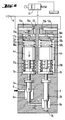
- reference 1 designates a valve body in which two separate needle valve units are housed and operationally arranged in series.
- a first needle valve unit includes a first valve needle 2a and is connected via a channel 6 to a supply of fuel under pressure, preferably supplied via a common line indicated by an arrow in the drawings.
- the needle valve 2a controls the feeding of fuel from a chamber 6a over a first valve sealing surface 7a, along a connecting channel 8, to a chamber 8a, from which a second valve needle 2b of a second needle valve unit controls the feeding of fuel over a second valve sealing surface 7b to a cylinder of the engine (not shown).
- the first needle valve further comprises a control element 3a, a piston device 4a, and an auxiliary piston 5a, which are operationally connected with each other.
- a compression spring lla is arranged between the control element 3a and the piston device 4a, the elements 3a and 4a being movable against the spring force of the spring.
- a compression spring 12a is arranged between the piston device 4a and the auxiliary piston 5a.
- the second needle valve unit is constructed in a manner corresponding to that of the first needle valve unit and comprises a valve needle 2b, a control element 3b, a piston device 4b, an auxiliary piston 5b and springs llb and 12b.
- the needle valves are controlled by a hydraulic oil circuit 9, which provides a basic control pressure for the needle valve units, and by a solenoid valve 10, with the assistance of which the opening and closing of the needle valve units are achieved through various chambers and constriction channels by utilizing pressure differences. Timing differences between the needle valves are effected by dimensioning factors, as will be later described in more detail.
- the hydraulic oil circuit 9 acts directly on chambers 13a and 13b, which are connected through constriction channels 14a and 14b to chambers 15a and 15b. In this manner the pressure of the hydraulic oil is communicated to chambers 16a and 16b and thus acts on auxiliary pistons 5a and 5b.
- the chamber 16a is connected through a constriction channel 17a to a chamber 18a between the piston device 4a and the auxiliary piston 5a.
- the chamber 16b is connected through a constriction channel 17b to a chamber 18b between the piston device 4b and the auxiliary piston 5b.
- the chambers 15a and 15b are connected to a chamber 20 through constriction channels 19a and 19b, which chamber 20 is connected to the solenoid valve 10.
- the chambers 13a and 13b are connected to channels 21a and 21b, respectively.
- the channels 21a and 21b are blocked by the auxiliary pistons 5a and 5b when the latter are in their uppermost positions (see FIGS. 1-5), but otherwise the channels 21a and 21b debouch into the chambers 16a and 16b, respectively.
- the needle valves operate as follows. In the situation shown in FIG. 1, where the solenoid valve 10 is closed, the pressure of the hydraulic oil in the circuit 9 acts on all the chambers and channels connected to the hydraulic oil system. The pressures in the chambers 18a and 18b, aided by the springs 12a and 12b, force the auxiliary pistons to their uppermost positions, blocking the channels 21a and 21b, and force the piston devices 4a and 4b downwards thereby urging the valve needles 2a and 2b into closed positions. When the solenoid valve 10 is opened (FIG. 3), the chamber 20 is connected through the valve 10 to substantially lower pressure, for example to atmospheric pressure, so that the pressure in the chamber 20 decreases rapidly.
- the pressure also decreases rapidly in chambers 15a and 16a and in chambers 15b and 16b, thereby allowing hydraulic oil to flow from the chambers 18a and 18b through the constriction channels 17a and 17b, respectively.
- the feed pressure of the fuel in the chamber 6a tends to lift the valve needle 2a and, and on the other hand, the pressure of the fuel remaining in the chamber 8a tends to lift the valve needle 2b.
- the velocities at which the valve needles 2a and 2b rise depend on how fast the oil in the chambers 18a and 18b is able to flow through the constriction channels 17a and 17b, allowing upward movement of the piston devices 4a and 4b. Because, according to the invention, the first needle valve is opened first, the diameter or cross sectional area of the piston device 4a is chosen so as to be smaller than the diameter of the piston device 4b. Consequently, in the event that the diameters of the constriction channels 17a and 17b correspond to each other, the piston device 4a moves faster upwards (as viewed in the figures) and the first needle valve opens first. The situation corresponds to that shown in FIG. 3.
- FIGS. 5 and 6 show the situation upon closing of the needle valves.
- the solenoid valve 10 closes and the connection of the chamber 20, and thereby also of the other chambers, to lower pressure is cut off, the pressures in the chambers 20, 15a and 15b, and 16a and 16b, begin to rise.
- the pressure in chamber 16a is greater than that in chamber 18a and the pressure in chamber 16b is greater than that in chamber 18b.
- the auxiliary pistons 5a and 5b start moving downwards, simultaneously opening the constriction channels 21a and 21b.
- the constriction channel 21b is selected to be of greater diameter than the constriction channel 21a, the pressure applied to the auxiliary piston 5b increases at a faster rate causing the second needle valve to close first whereupon the injection of fuel ends, cf. the situation in FIG. 5. Because of the constriction channels 19a and 19b, this greater pressure communicated through the constriction channel 21b is not communicated to the chamber 16a and does not act on the auxiliary piston 5a. Thus the downward movement of the auxiliary piston 5a and thereby the closing of the first needle valve are mainly dependent on the increased pressure being communicated through the constriction channel 21a. When the pressure has risen sufficiently, the first needle valve closes. The situation corresponds to that shown in FIG. 6.
- the pressure in the hydraulic oil circuit 9 is communicated to the chambers 18a and 18b through the constriction channels 17a and 17b, whereupon the increasing pressures in the chambers 18a and 18b and the force of the springs 12a and 12b move the auxiliary pistons 5a and 5b back to their initial positions shown in FIG. 1 in which the constriction channels 21a and 21b are again closed.
- the diameters of the constriction channels 14a and 14b are equal.
- the control in relative timing of the opening and closing of the needle valves is achieved through a difference in diameter of the piston device 4a relative to the piston device 4b and a difference in diameter of the constriction channel 21a relative to the constriction channel 21b.
- the constriction channel 17a were of greater diameter then the constriction channel 17b, it would be possible to ensure that the first needle valve opens before the second needle valve even if the diameters of the piston devices 4a and 4b were equal. Accordingly it is possible to alter the respective diameters and precise positions of the channels to ensure that the first needle valve opens first and closes last, which is advantageous for the operation of the system.
- the described structure operates so that the needle valves may open if the pressure in the hydraulic oil system goes down. For this reason it is advantageous to provide the common fuel supply line used for fuel injection with a safety device which quickly depressurizes the common line if the pressure of the hydraulic oil decreases to too low a level.
- a safety device is shown in EP-A-0964153.
- the hydraulic oil circuit may advantageously, for example, be part of the lubrication oil circuit of the engine, as long as the pressure of the lubrication oil is increased, for example by means of a booster pump, to a suitable level for controlling the valves, e.g. to about 200 bar.
- the solution according to the invention is particularly advantageous if heavy oil is used as the fuel being injected.
- each needle valve comprises several discrete parts operationally connected with each other. This construction is advantageous with respect to manufacture and assembly. However, other types of alternative constructions are also possible.
- the valve needles 2a and 2b may be attached to the control elements 3a and 3b if so desired.
- each needle valve In normal operation, the piston device 4 and the control element 3 of each needle valve move together as a unit unless the pressure of the fuel line and the pressure of the hydraulic oil circuit fall, in which case the spring 11 pushes the element 3 away from the piston device 4 and the needle valve closes.
- This feature ensures that the needle valves are closed when the system is not activated for use. For example, before starting the engine the pressure in the common line is low and there is no pressure in the hydraulic oil circuit 9. In this case the actions of the springs 11 close the needle valves and prevent entry of fuel into the cylinder.
Landscapes
- Engineering & Computer Science (AREA)
- Chemical & Material Sciences (AREA)
- Combustion & Propulsion (AREA)
- Mechanical Engineering (AREA)
- General Engineering & Computer Science (AREA)
- Physics & Mathematics (AREA)
- Fluid Mechanics (AREA)
- Fuel-Injection Apparatus (AREA)
Applications Claiming Priority (2)
| Application Number | Priority Date | Filing Date | Title |
|---|---|---|---|
| FI992707A FI112527B (fi) | 1999-12-16 | 1999-12-16 | Ruiskutusventtiilijärjestely |
| FI992707 | 1999-12-16 |
Publications (3)
| Publication Number | Publication Date |
|---|---|
| EP1111229A2 true EP1111229A2 (de) | 2001-06-27 |
| EP1111229A3 EP1111229A3 (de) | 2003-05-28 |
| EP1111229B1 EP1111229B1 (de) | 2007-04-18 |
Family
ID=8555759
Family Applications (1)
| Application Number | Title | Priority Date | Filing Date |
|---|---|---|---|
| EP00311108A Expired - Lifetime EP1111229B1 (de) | 1999-12-16 | 2000-12-12 | Kraftstoffeinspritzventil für Hubkolbenbrennkraftmaschine |
Country Status (6)
| Country | Link |
|---|---|
| US (1) | US6439193B2 (de) |
| EP (1) | EP1111229B1 (de) |
| JP (1) | JP2001193594A (de) |
| AT (1) | ATE360141T1 (de) |
| DE (1) | DE60034417T2 (de) |
| FI (1) | FI112527B (de) |
Cited By (18)
| Publication number | Priority date | Publication date | Assignee | Title |
|---|---|---|---|---|
| US6761325B2 (en) | 1998-09-16 | 2004-07-13 | Westport Research Inc. | Dual fuel injection valve and method of operating a dual fuel injection valve |
| WO2006000487A1 (de) * | 2004-06-24 | 2006-01-05 | Robert Bosch Gmbh | Kraftstoffeinspritzvorrichtung |
| ITMI20090947A1 (it) * | 2009-05-28 | 2010-11-29 | Poliauto Di Parietti Pietro & C Sn C | Dispositivo multifunzione per l'alimentazione di motori con un combustibile gassoso, in particolare per motori di veicoli |
| WO2012175795A3 (en) * | 2011-06-23 | 2013-02-21 | Wärtsilä Finland Oy | Fuel injection system for an internal combustion engine and method of operating a fuel injection system in an internal combustion engine |
| WO2014106525A1 (de) * | 2013-01-07 | 2014-07-10 | L'orange Gmbh | Doppelnadelinjektor |
| CN105275693A (zh) * | 2014-06-08 | 2016-01-27 | 董仲国 | 双针阀喷油器总成 |
| CN105626317A (zh) * | 2016-02-29 | 2016-06-01 | 哈尔滨工程大学 | 组合式双电磁燃气喷射装置 |
| CN105626316A (zh) * | 2016-02-29 | 2016-06-01 | 哈尔滨工程大学 | 组合式增压双电磁燃气喷射装置 |
| CN105673257A (zh) * | 2016-02-29 | 2016-06-15 | 哈尔滨工程大学 | 增压与非增压组合式双压电燃气喷射装置 |
| CN105697196A (zh) * | 2016-02-29 | 2016-06-22 | 哈尔滨工程大学 | 组合式增压与非增压双电磁燃气喷射装置 |
| CN105715412A (zh) * | 2016-02-29 | 2016-06-29 | 哈尔滨工程大学 | 组合式增压双压电燃气喷射装置 |
| CN105736186A (zh) * | 2016-02-29 | 2016-07-06 | 哈尔滨工程大学 | 增压电磁与增压压电组合式燃气喷射装置 |
| CN105756825A (zh) * | 2016-04-21 | 2016-07-13 | 哈尔滨工程大学 | 组合式电磁喷油-增压压电喷气混合燃料喷射装置 |
| CN105781796A (zh) * | 2016-02-29 | 2016-07-20 | 哈尔滨工程大学 | 电磁与增压压电组合式燃气喷射装置 |
| CN105781797A (zh) * | 2016-02-29 | 2016-07-20 | 哈尔滨工程大学 | 电磁与压电组合式燃气喷射装置 |
| CN105781798A (zh) * | 2016-02-29 | 2016-07-20 | 哈尔滨工程大学 | 组合式双压电燃气喷射装置 |
| CN105840371A (zh) * | 2016-04-21 | 2016-08-10 | 哈尔滨工程大学 | 组合式压电喷油-电磁喷气混合燃料喷射装置 |
| CN106499555A (zh) * | 2016-09-19 | 2017-03-15 | 哈尔滨工程大学 | 集成式电磁与双压电混合燃料喷射装置 |
Families Citing this family (15)
| Publication number | Priority date | Publication date | Assignee | Title |
|---|---|---|---|---|
| DE10063698A1 (de) * | 2000-12-20 | 2002-07-04 | Siemens Ag | Hochdruckeinspritzsystem mit Ausführung einer Steuerdrossel als Kaskadendrossel |
| US6647966B2 (en) * | 2001-09-21 | 2003-11-18 | Caterpillar Inc | Common rail fuel injection system and fuel injector for same |
| DE60314761T2 (de) * | 2003-12-12 | 2007-12-06 | Delphi Technologies, Inc., Troy | Einspritzventil mit Steuerungsventil, das den Druck im Steuerungsraum steuert |
| US7556017B2 (en) * | 2006-03-31 | 2009-07-07 | Caterpillar Inc. | Twin needle valve dual mode injector |
| WO2007131227A2 (en) * | 2006-05-05 | 2007-11-15 | Advanced Cerametrics, Inc. | Self-powered portable electronic device |
| SE530779C2 (sv) * | 2007-01-08 | 2008-09-09 | Scania Cv Ab | Bränslepump och en metod för att styra en bränslepump |
| US7451742B2 (en) * | 2007-10-29 | 2008-11-18 | Caterpillar Inc. | Engine having common rail intensifier and method |
| US8500045B2 (en) * | 2009-07-20 | 2013-08-06 | Caterpillar Inc. | Parallel circuit fuel filtration for fuel injectors |
| FI124121B (fi) * | 2010-12-01 | 2014-03-31 | Wärtsilä Finland Oy | Polttomoottorin ohjausmenetelmä ja polttomoottori |
| WO2014144581A1 (en) * | 2013-03-15 | 2014-09-18 | Mcalister Technologies, Llc | Internal combustion engine and associated systems and methods |
| US9206778B2 (en) * | 2013-04-19 | 2015-12-08 | Caterpillar Inc. | Dual fuel injector with F, A and Z orifice control |
| CA2820013C (en) * | 2013-06-28 | 2014-12-02 | Westport Power Inc. | Module for controlling fuel pressure in an internal combustion engine |
| US20140346254A1 (en) * | 2014-08-07 | 2014-11-27 | Caterpillar Inc. | Fuel injector for gaseous injection |
| CN105781836B (zh) * | 2016-04-21 | 2018-04-17 | 哈尔滨工程大学 | 组合式增压燃油‑非增压燃气双电磁混合燃料喷射装置 |
| US11035332B2 (en) | 2017-12-19 | 2021-06-15 | Caterpillar Inc. | Fuel injector having dual solenoid control valves |
Citations (1)
| Publication number | Priority date | Publication date | Assignee | Title |
|---|---|---|---|---|
| EP0964153A2 (de) | 1998-06-08 | 1999-12-15 | Wärtsilä NSD Oy Ab | Steuer- und Sicherheitsventil für Brennstoffversorgungssystem |
Family Cites Families (9)
| Publication number | Priority date | Publication date | Assignee | Title |
|---|---|---|---|---|
| DE3009750A1 (de) * | 1980-03-14 | 1981-09-24 | M.A.N. Maschinenfabrik Augsburg-Nürnberg AG, 8900 Augsburg | Brennstoffeinspritzvorrichtung fuer brennkraftmaschinen |
| JPS61187567A (ja) | 1985-02-15 | 1986-08-21 | Kawasaki Heavy Ind Ltd | ガス噴射弁 |
| DE4340305C2 (de) * | 1993-11-26 | 1998-02-19 | Daimler Benz Ag | Kraftstoffeinspritzdüse für eine Brennkraftmaschine |
| US5732679A (en) * | 1995-04-27 | 1998-03-31 | Isuzu Motors Limited | Accumulator-type fuel injection system |
| DE19706467C1 (de) * | 1997-02-19 | 1998-03-26 | Daimler Benz Ag | Speichereinspritzsystem für eine mehrzylindrige Brennkraftmaschine |
| US5899389A (en) * | 1997-06-02 | 1999-05-04 | Cummins Engine Company, Inc. | Two stage fuel injector nozzle assembly |
| DE19749001A1 (de) * | 1997-11-06 | 1999-05-27 | Daimler Chrysler Ag | Speichereinspritzsystem für eine mehrzylindrige Brennkraftmaschine |
| EP0961024B1 (de) | 1998-05-29 | 2010-01-13 | Wärtsilä Schweiz AG | Brennstoffeinspritzdüse |
| US6073862A (en) * | 1998-09-16 | 2000-06-13 | Westport Research Inc. | Gaseous and liquid fuel injector |
-
1999
- 1999-12-16 FI FI992707A patent/FI112527B/fi not_active IP Right Cessation
-
2000
- 2000-12-12 EP EP00311108A patent/EP1111229B1/de not_active Expired - Lifetime
- 2000-12-12 DE DE60034417T patent/DE60034417T2/de not_active Expired - Lifetime
- 2000-12-12 AT AT00311108T patent/ATE360141T1/de not_active IP Right Cessation
- 2000-12-14 JP JP2000379627A patent/JP2001193594A/ja active Pending
- 2000-12-15 US US09/737,424 patent/US6439193B2/en not_active Expired - Fee Related
Patent Citations (1)
| Publication number | Priority date | Publication date | Assignee | Title |
|---|---|---|---|---|
| EP0964153A2 (de) | 1998-06-08 | 1999-12-15 | Wärtsilä NSD Oy Ab | Steuer- und Sicherheitsventil für Brennstoffversorgungssystem |
Cited By (24)
| Publication number | Priority date | Publication date | Assignee | Title |
|---|---|---|---|---|
| US6761325B2 (en) | 1998-09-16 | 2004-07-13 | Westport Research Inc. | Dual fuel injection valve and method of operating a dual fuel injection valve |
| US7124959B2 (en) | 1998-09-16 | 2006-10-24 | Westport Power Inc. | Dual fuel injection valve and method of operating a dual fuel injection valve |
| WO2006000487A1 (de) * | 2004-06-24 | 2006-01-05 | Robert Bosch Gmbh | Kraftstoffeinspritzvorrichtung |
| ITMI20090947A1 (it) * | 2009-05-28 | 2010-11-29 | Poliauto Di Parietti Pietro & C Sn C | Dispositivo multifunzione per l'alimentazione di motori con un combustibile gassoso, in particolare per motori di veicoli |
| WO2012175795A3 (en) * | 2011-06-23 | 2013-02-21 | Wärtsilä Finland Oy | Fuel injection system for an internal combustion engine and method of operating a fuel injection system in an internal combustion engine |
| WO2014106525A1 (de) * | 2013-01-07 | 2014-07-10 | L'orange Gmbh | Doppelnadelinjektor |
| CN105275693A (zh) * | 2014-06-08 | 2016-01-27 | 董仲国 | 双针阀喷油器总成 |
| CN105275693B (zh) * | 2014-06-08 | 2019-11-08 | 董仲国 | 双针阀喷油器总成 |
| CN105736186A (zh) * | 2016-02-29 | 2016-07-06 | 哈尔滨工程大学 | 增压电磁与增压压电组合式燃气喷射装置 |
| CN105781797A (zh) * | 2016-02-29 | 2016-07-20 | 哈尔滨工程大学 | 电磁与压电组合式燃气喷射装置 |
| CN105697196A (zh) * | 2016-02-29 | 2016-06-22 | 哈尔滨工程大学 | 组合式增压与非增压双电磁燃气喷射装置 |
| CN105715412A (zh) * | 2016-02-29 | 2016-06-29 | 哈尔滨工程大学 | 组合式增压双压电燃气喷射装置 |
| CN105626316A (zh) * | 2016-02-29 | 2016-06-01 | 哈尔滨工程大学 | 组合式增压双电磁燃气喷射装置 |
| CN105626317A (zh) * | 2016-02-29 | 2016-06-01 | 哈尔滨工程大学 | 组合式双电磁燃气喷射装置 |
| CN105781796A (zh) * | 2016-02-29 | 2016-07-20 | 哈尔滨工程大学 | 电磁与增压压电组合式燃气喷射装置 |
| CN105673257A (zh) * | 2016-02-29 | 2016-06-15 | 哈尔滨工程大学 | 增压与非增压组合式双压电燃气喷射装置 |
| CN105781798A (zh) * | 2016-02-29 | 2016-07-20 | 哈尔滨工程大学 | 组合式双压电燃气喷射装置 |
| CN105781796B (zh) * | 2016-02-29 | 2018-01-19 | 哈尔滨工程大学 | 电磁与增压压电组合式燃气喷射装置 |
| CN105697196B (zh) * | 2016-02-29 | 2017-12-19 | 哈尔滨工程大学 | 组合式增压与非增压双电磁燃气喷射装置 |
| CN105626317B (zh) * | 2016-02-29 | 2017-12-01 | 哈尔滨工程大学 | 组合式双电磁燃气喷射装置 |
| CN105840371A (zh) * | 2016-04-21 | 2016-08-10 | 哈尔滨工程大学 | 组合式压电喷油-电磁喷气混合燃料喷射装置 |
| CN105840371B (zh) * | 2016-04-21 | 2018-05-18 | 哈尔滨工程大学 | 组合式压电喷油-电磁喷气混合燃料喷射装置 |
| CN105756825A (zh) * | 2016-04-21 | 2016-07-13 | 哈尔滨工程大学 | 组合式电磁喷油-增压压电喷气混合燃料喷射装置 |
| CN106499555A (zh) * | 2016-09-19 | 2017-03-15 | 哈尔滨工程大学 | 集成式电磁与双压电混合燃料喷射装置 |
Also Published As
| Publication number | Publication date |
|---|---|
| DE60034417T2 (de) | 2008-01-03 |
| EP1111229A3 (de) | 2003-05-28 |
| US20010003976A1 (en) | 2001-06-21 |
| US6439193B2 (en) | 2002-08-27 |
| FI112527B (fi) | 2003-12-15 |
| DE60034417D1 (de) | 2007-05-31 |
| EP1111229B1 (de) | 2007-04-18 |
| JP2001193594A (ja) | 2001-07-17 |
| ATE360141T1 (de) | 2007-05-15 |
| FI19992707A (fi) | 2001-06-17 |
Similar Documents
| Publication | Publication Date | Title |
|---|---|---|
| EP1111229B1 (de) | Kraftstoffeinspritzventil für Hubkolbenbrennkraftmaschine | |
| US6145492A (en) | Control valve for a fuel injection valve | |
| JP3742669B2 (ja) | 内燃機関用の燃料噴射装置 | |
| GB2276918A (en) | I.c. engine fuel pumping injection nozzle | |
| US6644282B2 (en) | Fuel injection system with fuel pressure intensification | |
| US5058614A (en) | Device for controlling the lift of a hydraulically operated valve | |
| US5295470A (en) | Fuel injection apparatus for internal combustion engines | |
| RU2000107804A (ru) | Электронная инжекторная топливная система, приводимая в действие с помощью гидравлики | |
| US6532943B1 (en) | Hydraulically actuated electronically controlled fuel injection system | |
| JPH08921A (ja) | 高圧流体圧装置用エッジフィルタ | |
| US5626119A (en) | Fuel system | |
| US4708116A (en) | Injection system for a diesel engine with a high pressure injection pump for each cylinder | |
| US6637409B2 (en) | Fuel injection device for internal combustion engines | |
| US6871636B2 (en) | Fuel-injection device for internal combustion engines | |
| JP4253659B2 (ja) | 高圧液体システム、特に内燃機関のための燃料噴射装置の高圧液体システム内に設けられた接続部を制御するための弁 | |
| JP2004518881A (ja) | 3ポート2位置弁 | |
| JP4045922B2 (ja) | 内燃機関用燃料噴射装置 | |
| US20020092501A1 (en) | Control valve for hydraulically oil activated fuel injector | |
| US20040101420A1 (en) | Solenoid regulated pump assembly | |
| US20090173316A1 (en) | Injection means for a combustion engine | |
| EP1287256B1 (de) | Brennstoffeinspritzventil | |
| JP2006233805A (ja) | 燃料噴射装置 | |
| US20040163625A1 (en) | Fuel injector | |
| US7451743B2 (en) | Fuel injection system with accumulator fill valve assembly | |
| SU1343081A1 (ru) | Система подачи топлива дл дизел |
Legal Events
| Date | Code | Title | Description |
|---|---|---|---|
| PUAI | Public reference made under article 153(3) epc to a published international application that has entered the european phase |
Free format text: ORIGINAL CODE: 0009012 |
|
| AK | Designated contracting states |
Kind code of ref document: A2 Designated state(s): AT BE CH CY DE DK ES FI FR GB GR IE IT LI LU MC NL PT SE TR |
|
| AX | Request for extension of the european patent |
Free format text: AL;LT;LV;MK;RO;SI |
|
| PUAL | Search report despatched |
Free format text: ORIGINAL CODE: 0009013 |
|
| AK | Designated contracting states |
Designated state(s): AT BE CH CY DE DK ES FI FR GB GR IE IT LI LU MC NL PT SE TR |
|
| AX | Request for extension of the european patent |
Extension state: AL LT LV MK RO SI |
|
| RIC1 | Information provided on ipc code assigned before grant |
Ipc: 7F 02M 47/04 A Ipc: 7F 02M 63/00 B Ipc: 7F 02M 61/20 B |
|
| RAP1 | Party data changed (applicant data changed or rights of an application transferred) |
Owner name: WAERTSILAE TECHNOLOGY OY AB |
|
| 17P | Request for examination filed |
Effective date: 20031031 |
|
| RAP1 | Party data changed (applicant data changed or rights of an application transferred) |
Owner name: WAERTSILAE FINLAND OY |
|
| AKX | Designation fees paid |
Designated state(s): AT BE CH CY DE DK ES FI FR GB GR IE IT LI LU MC NL PT SE TR |
|
| GRAP | Despatch of communication of intention to grant a patent |
Free format text: ORIGINAL CODE: EPIDOSNIGR1 |
|
| GRAS | Grant fee paid |
Free format text: ORIGINAL CODE: EPIDOSNIGR3 |
|
| GRAA | (expected) grant |
Free format text: ORIGINAL CODE: 0009210 |
|
| AK | Designated contracting states |
Kind code of ref document: B1 Designated state(s): AT BE CH CY DE DK ES FI FR GB GR IE IT LI LU MC NL PT SE TR |
|
| PG25 | Lapsed in a contracting state [announced via postgrant information from national office to epo] |
Ref country code: LI Free format text: LAPSE BECAUSE OF FAILURE TO SUBMIT A TRANSLATION OF THE DESCRIPTION OR TO PAY THE FEE WITHIN THE PRESCRIBED TIME-LIMIT Effective date: 20070418 Ref country code: CH Free format text: LAPSE BECAUSE OF FAILURE TO SUBMIT A TRANSLATION OF THE DESCRIPTION OR TO PAY THE FEE WITHIN THE PRESCRIBED TIME-LIMIT Effective date: 20070418 Ref country code: FI Free format text: LAPSE BECAUSE OF FAILURE TO SUBMIT A TRANSLATION OF THE DESCRIPTION OR TO PAY THE FEE WITHIN THE PRESCRIBED TIME-LIMIT Effective date: 20070418 |
|
| REG | Reference to a national code |
Ref country code: CH Ref legal event code: EP |
|
| REG | Reference to a national code |
Ref country code: IE Ref legal event code: FG4D |
|
| REF | Corresponds to: |
Ref document number: 60034417 Country of ref document: DE Date of ref document: 20070531 Kind code of ref document: P |
|
| PG25 | Lapsed in a contracting state [announced via postgrant information from national office to epo] |
Ref country code: SE Free format text: LAPSE BECAUSE OF FAILURE TO SUBMIT A TRANSLATION OF THE DESCRIPTION OR TO PAY THE FEE WITHIN THE PRESCRIBED TIME-LIMIT Effective date: 20070718 |
|
| PG25 | Lapsed in a contracting state [announced via postgrant information from national office to epo] |
Ref country code: ES Free format text: LAPSE BECAUSE OF FAILURE TO SUBMIT A TRANSLATION OF THE DESCRIPTION OR TO PAY THE FEE WITHIN THE PRESCRIBED TIME-LIMIT Effective date: 20070729 |
|
| PG25 | Lapsed in a contracting state [announced via postgrant information from national office to epo] |
Ref country code: PT Free format text: LAPSE BECAUSE OF FAILURE TO SUBMIT A TRANSLATION OF THE DESCRIPTION OR TO PAY THE FEE WITHIN THE PRESCRIBED TIME-LIMIT Effective date: 20070918 |
|
| REG | Reference to a national code |
Ref country code: CH Ref legal event code: PL |
|
| NLV1 | Nl: lapsed or annulled due to failure to fulfill the requirements of art. 29p and 29m of the patents act | ||
| PG25 | Lapsed in a contracting state [announced via postgrant information from national office to epo] |
Ref country code: AT Free format text: LAPSE BECAUSE OF FAILURE TO SUBMIT A TRANSLATION OF THE DESCRIPTION OR TO PAY THE FEE WITHIN THE PRESCRIBED TIME-LIMIT Effective date: 20070418 |
|
| EN | Fr: translation not filed | ||
| PG25 | Lapsed in a contracting state [announced via postgrant information from national office to epo] |
Ref country code: BE Free format text: LAPSE BECAUSE OF FAILURE TO SUBMIT A TRANSLATION OF THE DESCRIPTION OR TO PAY THE FEE WITHIN THE PRESCRIBED TIME-LIMIT Effective date: 20070418 |
|
| PG25 | Lapsed in a contracting state [announced via postgrant information from national office to epo] |
Ref country code: DK Free format text: LAPSE BECAUSE OF FAILURE TO SUBMIT A TRANSLATION OF THE DESCRIPTION OR TO PAY THE FEE WITHIN THE PRESCRIBED TIME-LIMIT Effective date: 20070418 Ref country code: NL Free format text: LAPSE BECAUSE OF FAILURE TO SUBMIT A TRANSLATION OF THE DESCRIPTION OR TO PAY THE FEE WITHIN THE PRESCRIBED TIME-LIMIT Effective date: 20070418 |
|
| PLBE | No opposition filed within time limit |
Free format text: ORIGINAL CODE: 0009261 |
|
| STAA | Information on the status of an ep patent application or granted ep patent |
Free format text: STATUS: NO OPPOSITION FILED WITHIN TIME LIMIT |
|
| 26N | No opposition filed |
Effective date: 20080121 |
|
| PG25 | Lapsed in a contracting state [announced via postgrant information from national office to epo] |
Ref country code: GR Free format text: LAPSE BECAUSE OF FAILURE TO SUBMIT A TRANSLATION OF THE DESCRIPTION OR TO PAY THE FEE WITHIN THE PRESCRIBED TIME-LIMIT Effective date: 20070719 Ref country code: FR Free format text: LAPSE BECAUSE OF FAILURE TO SUBMIT A TRANSLATION OF THE DESCRIPTION OR TO PAY THE FEE WITHIN THE PRESCRIBED TIME-LIMIT Effective date: 20071214 |
|
| PG25 | Lapsed in a contracting state [announced via postgrant information from national office to epo] |
Ref country code: MC Free format text: LAPSE BECAUSE OF NON-PAYMENT OF DUE FEES Effective date: 20071231 |
|
| PG25 | Lapsed in a contracting state [announced via postgrant information from national office to epo] |
Ref country code: IE Free format text: LAPSE BECAUSE OF NON-PAYMENT OF DUE FEES Effective date: 20071212 |
|
| PG25 | Lapsed in a contracting state [announced via postgrant information from national office to epo] |
Ref country code: FR Free format text: LAPSE BECAUSE OF FAILURE TO SUBMIT A TRANSLATION OF THE DESCRIPTION OR TO PAY THE FEE WITHIN THE PRESCRIBED TIME-LIMIT Effective date: 20070418 |
|
| PG25 | Lapsed in a contracting state [announced via postgrant information from national office to epo] |
Ref country code: CY Free format text: LAPSE BECAUSE OF FAILURE TO SUBMIT A TRANSLATION OF THE DESCRIPTION OR TO PAY THE FEE WITHIN THE PRESCRIBED TIME-LIMIT Effective date: 20070418 |
|
| PG25 | Lapsed in a contracting state [announced via postgrant information from national office to epo] |
Ref country code: LU Free format text: LAPSE BECAUSE OF NON-PAYMENT OF DUE FEES Effective date: 20071212 |
|
| PG25 | Lapsed in a contracting state [announced via postgrant information from national office to epo] |
Ref country code: TR Free format text: LAPSE BECAUSE OF FAILURE TO SUBMIT A TRANSLATION OF THE DESCRIPTION OR TO PAY THE FEE WITHIN THE PRESCRIBED TIME-LIMIT Effective date: 20070418 |
|
| PGFP | Annual fee paid to national office [announced via postgrant information from national office to epo] |
Ref country code: GB Payment date: 20101221 Year of fee payment: 11 Ref country code: IT Payment date: 20101227 Year of fee payment: 11 |
|
| PGFP | Annual fee paid to national office [announced via postgrant information from national office to epo] |
Ref country code: DE Payment date: 20101222 Year of fee payment: 11 |
|
| GBPC | Gb: european patent ceased through non-payment of renewal fee |
Effective date: 20111212 |
|
| REG | Reference to a national code |
Ref country code: DE Ref legal event code: R119 Ref document number: 60034417 Country of ref document: DE Effective date: 20120703 |
|
| PG25 | Lapsed in a contracting state [announced via postgrant information from national office to epo] |
Ref country code: GB Free format text: LAPSE BECAUSE OF NON-PAYMENT OF DUE FEES Effective date: 20111212 Ref country code: DE Free format text: LAPSE BECAUSE OF NON-PAYMENT OF DUE FEES Effective date: 20120703 |
|
| PG25 | Lapsed in a contracting state [announced via postgrant information from national office to epo] |
Ref country code: IT Free format text: LAPSE BECAUSE OF NON-PAYMENT OF DUE FEES Effective date: 20111212 |