EP1110684A1 - Unité de façonnage et massicotage à couteaux circulaires et guillotine - Google Patents
Unité de façonnage et massicotage à couteaux circulaires et guillotine Download PDFInfo
- Publication number
- EP1110684A1 EP1110684A1 EP20000403507 EP00403507A EP1110684A1 EP 1110684 A1 EP1110684 A1 EP 1110684A1 EP 20000403507 EP20000403507 EP 20000403507 EP 00403507 A EP00403507 A EP 00403507A EP 1110684 A1 EP1110684 A1 EP 1110684A1
- Authority
- EP
- European Patent Office
- Prior art keywords
- cutting
- shaping
- sheet
- knife
- guide bar
- Prior art date
- Legal status (The legal status is an assumption and is not a legal conclusion. Google has not performed a legal analysis and makes no representation as to the accuracy of the status listed.)
- Granted
Links
- 238000007493 shaping process Methods 0.000 title claims description 22
- 238000009966 trimming Methods 0.000 title claims description 6
- 238000006073 displacement reaction Methods 0.000 claims abstract description 18
- 239000000463 material Substances 0.000 claims abstract description 6
- 239000000123 paper Substances 0.000 claims description 19
- 238000013016 damping Methods 0.000 claims description 9
- 230000006641 stabilisation Effects 0.000 claims description 6
- 238000011105 stabilization Methods 0.000 claims description 6
- 230000000903 blocking effect Effects 0.000 claims description 4
- 238000004080 punching Methods 0.000 claims description 2
- YEXPOXQUZXUXJW-UHFFFAOYSA-N oxolead Chemical compound [Pb]=O YEXPOXQUZXUXJW-UHFFFAOYSA-N 0.000 description 4
- 230000000694 effects Effects 0.000 description 2
- 230000007704 transition Effects 0.000 description 2
- 101100008046 Caenorhabditis elegans cut-2 gene Proteins 0.000 description 1
- 230000000295 complement effect Effects 0.000 description 1
- 230000006835 compression Effects 0.000 description 1
- 238000007906 compression Methods 0.000 description 1
- 230000006837 decompression Effects 0.000 description 1
- 238000012423 maintenance Methods 0.000 description 1
- 238000004519 manufacturing process Methods 0.000 description 1
- 239000002184 metal Substances 0.000 description 1
- 239000005418 vegetable material Substances 0.000 description 1
- 235000013311 vegetables Nutrition 0.000 description 1
Images


Classifications
-
- B—PERFORMING OPERATIONS; TRANSPORTING
- B26—HAND CUTTING TOOLS; CUTTING; SEVERING
- B26D—CUTTING; DETAILS COMMON TO MACHINES FOR PERFORATING, PUNCHING, CUTTING-OUT, STAMPING-OUT OR SEVERING
- B26D11/00—Combinations of several similar cutting apparatus
-
- B—PERFORMING OPERATIONS; TRANSPORTING
- B26—HAND CUTTING TOOLS; CUTTING; SEVERING
- B26D—CUTTING; DETAILS COMMON TO MACHINES FOR PERFORATING, PUNCHING, CUTTING-OUT, STAMPING-OUT OR SEVERING
- B26D5/00—Arrangements for operating and controlling machines or devices for cutting, cutting-out, stamping-out, punching, perforating, or severing by means other than cutting
- B26D5/02—Means for moving the cutting member into its operative position for cutting
-
- B—PERFORMING OPERATIONS; TRANSPORTING
- B26—HAND CUTTING TOOLS; CUTTING; SEVERING
- B26D—CUTTING; DETAILS COMMON TO MACHINES FOR PERFORATING, PUNCHING, CUTTING-OUT, STAMPING-OUT OR SEVERING
- B26D9/00—Cutting apparatus combined with punching or perforating apparatus or with dissimilar cutting apparatus
-
- Y—GENERAL TAGGING OF NEW TECHNOLOGICAL DEVELOPMENTS; GENERAL TAGGING OF CROSS-SECTIONAL TECHNOLOGIES SPANNING OVER SEVERAL SECTIONS OF THE IPC; TECHNICAL SUBJECTS COVERED BY FORMER USPC CROSS-REFERENCE ART COLLECTIONS [XRACs] AND DIGESTS
- Y10—TECHNICAL SUBJECTS COVERED BY FORMER USPC
- Y10T—TECHNICAL SUBJECTS COVERED BY FORMER US CLASSIFICATION
- Y10T83/00—Cutting
- Y10T83/768—Rotatable disc tool pair or tool and carrier
- Y10T83/7872—Tool element mounted for adjustment
-
- Y—GENERAL TAGGING OF NEW TECHNOLOGICAL DEVELOPMENTS; GENERAL TAGGING OF CROSS-SECTIONAL TECHNOLOGIES SPANNING OVER SEVERAL SECTIONS OF THE IPC; TECHNICAL SUBJECTS COVERED BY FORMER USPC CROSS-REFERENCE ART COLLECTIONS [XRACs] AND DIGESTS
- Y10—TECHNICAL SUBJECTS COVERED BY FORMER USPC
- Y10T—TECHNICAL SUBJECTS COVERED BY FORMER US CLASSIFICATION
- Y10T83/00—Cutting
- Y10T83/869—Means to drive or to guide tool
- Y10T83/8748—Tool displaceable to inactive position [e.g., for work loading]
- Y10T83/8749—By pivotal motion
Definitions
- the present invention relates to a shaping and trimming unit. say to cut or crease or perforate or cut halfway through, leaves into vegetable matter, such as paper, cardboard, plastic supports or similar.
- the invention relates more particularly to a cutter making it possible to cut or to groove or perforate or cut halfway through, from large format sheets, pre-printed rectangular items of various sizes, such as visit or invitation, labels and the like.
- the shaping and trimming unit presented here provides a solution to this Technical problem.
- This unit is easy to use, which allows its easy handling by non-professionals who can thus carry out quickly precise and careful cuts and shaping.
- the present invention aims to provide a solution to these technical problems.
- the invention thus relates to a unit for shaping and cutting knives circular and guillotine, to shape and cut a sheet of flexible material, such as paper, cardboard or a plastic support, comprising several cutting boxes each comprising a circular knife for cutting or shape the sheet continuously in a direction parallel to its direction of displacement and at least one guillotine to cut or shape the sheet in a direction transverse to its direction of movement, each knife circular that can rest on the sheet in an area where it is in press on a rotating roller whose axis is perpendicular to the direction of displacement of the sheet according to the invention, this unit is characterized in that that the cutting boxes are fixed in an adjustable way on a guide bar extending transversely to the direction of movement of the sheet, and this that the circular knives are removably attached to the said housings of chopped off.
- each guide bar carries several cutting boxes.
- the shaping and cutting unit comprises several bars parallel and spaced guideways in the direction of travel of the leaf.
- the shaping and trimming unit includes a cutting box 2, a guide bar 3 and a counter knife 4.
- the guide bar 3 is fixed. It carries the cutting box 2 and intervenes in guiding and moving said cutting box.
- the guide bar 3 comprises at least one groove which intervenes during the blocking of the cutting unit 2 against the leaf of vegetable material and the counter knife 4.
- the counter knife 4 can be a continuous roller.
- the outer surface of the counter knife is metallic.
- the axis G of the guide bar 3 is parallel to the axis of rotation H of the roller 4.
- a cutting box 2 comprises a knife 5, an arm 6 and a device for movement of the cutting box 7.
- the knife 5 of the cutting box 2 is circular and can be separated from the arm. AT this effect, simply remove the button 5a from the end of the axis carrying the knife 5. It is rotating around an axis I.
- the knife 5 has a blade metallic whose hardness is lower than the hardness of the metal composing the outer surface of the counter knife 4.
- the arm 6 has the function of carrying the knife 5 and allows movement without danger of the knife by the user.
- the displacement device 7 intervenes during the displacement of the housing of section 2.
- the displacement of the cutting box 2 can be done along the bar guide 3 and / or by rotation about the axis G of said guide bar.
- the displacement device 7 of the cutting box 2 is in the form a washer rotating around the guide bar along the axis G. We we will then speak of a displacement device or washer 7.
- the washer 7 and the arm 6 of the cutting unit 2 are secured by nesting mutual.
- the arm 6 has an appendage 8a which is housed in a housing 8b of the washer 7 adapted to its size and a protuberance 9b of the washer extending around the guide bar 3 fits into a space 9a arm suitable 6.
- the displacement device 7 comprises a means of blocking / unblocking 10 and a stabilization device 11 of the cutting unit 2 in a number of positions around the guide bar 3.
- the stabilization device 11 of the cutting unit 2 is a subset of a in one piece consisting of a push screw and spring. It includes a spring 12 and a ball 13 housed in a tube-shaped cavity closed at one of its extremities. The second end of the tube is open and is in direct contact with the outer surface of the guide bar 3.
- the locking / unlocking means 10 makes it possible to block the displacement 7 and therefore the cutting unit 2 in a given position along of the guide bar 3 and / or in a given position around said bar guide.
- the locking / unlocking means 10 can be a screw called a screw.
- locking / unlocking 10 includes a screw 10a, a body 10b and an end 10c or point of screw, opposite the head 10a of the screw.
- the head 10a of the locking / unlocking screw is located outside the device 7 and is easy to access for the user.
- the body 10b of the screw is partly housed in a tube-shaped cavity, one of the orifices is located at the level of the external lateral surface 7a of the washer 7 and the other end is located at the internal lateral surface 7b washer 7 in direct contact with the outer surface of the guide bar 3.
- the point 10c of the locking / unlocking screw 10 has a shape complementary to the shape of the hollow of at least one of the grooves of the guide bar 3 of so as to be able to lodge in said hollow.
- the length of the groove depends on the mobility that one wishes to give to the cutting box 2 along the guide bar 3.
- the guide bar 3 may include two other grooves intervening during stabilization of the cutting unit 2 in a given position around the guide bar 3.
- the working position ( Figure 6) is an unstable position.
- the three grooves A, B and C are located at the same distance from each other.
- Figure 3 shows the cutting box 2 in its change position of tool. In this position, the ball 13 of the stabilization device 11 of the housing of cutting 2 is housed in groove A of the guide bar 3.
- Figure 4 shows the cutting unit 2 in its rest position. In this position, the ball 13 is housed in the groove B.
- Figure 5 shows the cutting unit 2 in its damping position. In this position, the ball 13 is housed in the groove C.
- the transition to one or other of the positions described above is done by rotation of the cutting unit 2 around the guide bar 3 in the direction of clockwise or counterclockwise depending on the starting position and the desired ending position.
- the output of the cutting unit 2 from a stable position results in the output of the ball 13 of one of the grooves and the compression of the spring 12.
- the working position (figure 6) is an unstable position in the direction where the ball 13 is not housed in a groove.
- the washer 7 then performs a slight rotation about its axis G of rotation which is also the axis of the guide bar 3 and the blade of the knife 5 between in contact with the sheet 14 to be shaped which moves in the direction indicated by arrow F.
- the working position (figure 6) is unstable in the sense that under the effect of slightest impact against the blade of the knife 5 or of the cutting box 2, by example, ball 13 can re-enter groove C and thus pass from the working position (figure 5) to the damping position (figure 4).
- a locking means 10 can be used which can be for example a screw blocking / unblocking.
- the screw 10 is screwed and the point 10c of said screw is housed in groove A which, in the working position ( Figure 5), is opposite the tip 10c of the locking / unlocking screw 10.
- this same point 10c of the screw is slightly offset by compared to groove A.
- the housing section 2 may have a positioning device 15 of the arm 6 allowing adapt the position of arm 6 according to the desired job: creasing the paper, cutting, perforating, half-cutting of paper among others and of the type of paper: thin or thick for example.
- a creasing job will require a pressure of the knife 5 on the paper less important than in the case of cutting work.
- Cutting thick cardboard-type paper will require knife pressure 5 on the paper more important than in the case of a paper of light weight.
- the pressure device 15 of the cutting unit 2 is located in the washer 7 of the cutting box 2.
- the pressure device 15 is composed of a pressure screw 16, of a spring 17, a positioning screw 18 and the appendix 8a of the arm 6 housed in the housing 8b of the washer 7.
- the housing of the positioning screw 18 has two holes. One of these orifices open to the outside, while the second orifice opens to the housing 8b of appendix 8a of arm 6.
- the pressure screw 16 and the spring 17 of the pressure device 15 are housed in a housing having two orifices. One of these holes opens towards the outside of the washer 7, while the second orifice opens onto the housing 8b of appendix 8a of arm 6.
- the pressure screw 16 is integral with the spring 17 of the pressure device 15.
- the spring 17 has one of these ends in contact with the head 8c of appendix 8a of arm 6, while the other end is in contact with the point 16c of the screw pressure 16.
- the heads 16a and 18a of the pressure 16 and positioning 18 screws are accessible by the user at the orifices of their respective housing opening on the outside of the washer 7.
- the head 8c of appendix 8a of the arm 6 of the cutting unit 2 is more or less pushed back towards the spring 17 and said spring is more or less compressed when the housing of cut 2 passes from its damping position ( Figure 7) to its position work ( Figure 8).
- the spring 17 is more or less pushed back against the head 8c of appendix 8a of the arm 6 of the housing section 2, the spring 17 is therefore more or less compressed.
- FIGS. 9 and 10 show a machine 20 comprising a unit of guillotine 22, comprising guillotines as described above, placed at the output of a printing or photocopying unit 21.
- the paper 14 to be cut from the printing or photocopying unit 21 is guided in the cutter unit 22 by guides 23. These guides 23 are positioned according to the width and position of the sheet 14 of guide paper.
- the direction of paper travel is indicated by the arrow F.
- the paper 14 is driven in the direction F by pairs of rollers drive 24 opposite, themselves driven by motors 25 via belts 26.
- the paper 14 can be creased and / or cut, or perforated or cut halfway through continuous or discontinuous in the longitudinal direction of the sheet and then cut in the transverse direction by a guillotine guillotine 27.
- the unit according to the invention can comprise at least two guillotines, one being for cutting and the other for punching or creasing or half-cut.
- This machine therefore has the advantage of being able to manufacture at the same time articles of different sizes and shapes depending on the setting of the positioning of the cutting unit 2 on its guide bar 3 and in function knife type 5 used (grooving knife, cutting knife discontinuous and continuous cutting knife for example).
- Cards 28 or 29 are collected directly in a container 30 at their exit.
- the cutter according to the invention further comprises a button for controlling advance or retreat of the sheet to bring it under the knives, which provides maximum precision for placing knives on lines cutting.
- the box carrying the knives also has a circlip which allows prevent movement of the arm.
- the operation of the shaping and cutting unit according to the invention in particular the displacement of the leaf and that of the guillotine (s), can be digitally ordered.
Landscapes
- Life Sciences & Earth Sciences (AREA)
- Forests & Forestry (AREA)
- Engineering & Computer Science (AREA)
- Mechanical Engineering (AREA)
- Perforating, Stamping-Out Or Severing By Means Other Than Cutting (AREA)
- Details Of Cutting Devices (AREA)
- Processing And Handling Of Plastics And Other Materials For Molding In General (AREA)
- Nonmetal Cutting Devices (AREA)
- Harvester Elements (AREA)
- Treatment And Processing Of Natural Fur Or Leather (AREA)
- Credit Cards Or The Like (AREA)
Abstract
Description
- une position de travail dans laquelle la lame du couteau circulaire prend appui sur la feuille à façonner ou à découper,
- une position d'inactivité dans laquelle la lame du couteau n'est pas en contact avec la feuille.
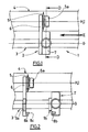
- la figure 1 représente, en vue de dessus, le boítier de coupe du massicot sur une barre de guidage selon un mode de réalisation de l'invention ;
- la figure 2 représente, en vue de dessus, le boítier de coupe du massicot de la figure 1 avec le bras portant le couteau dissocié du dispositif de déplacement;
- les figures 3 à 6 représentent le boítier de coupe de la figure 1 en coupe partielle transversale D-D selon la direction E;
- la figure 3 représente le boítier de coupe en position de changement d'outil ;
- la figure 4 représente le boítier de coupe en position de repos ;
- la figure 5 représente le boítier de coupe en position d'amortissement ;
- la figure 6 représente le boítier de coupe en position de travail ;
- la figure 7 représente un mode de réalisation préféré du boítier de coupe en position d'amortissement en coupe transversale;
- la figure 8 représente le boítier de coupe de la figure 7 en position de travail ;
- la figure 9 représente une machine à massicoter en vue de dessus ;
- la figure 10 représente la machine à massicoter de la figure 9 en coupe transversale.
- position de changement d'outil (figure 3);
- position de repos (figure 4);
- position d'amortissement (figure 5).
- usure moindre du rouleau 4 à surface lisse du fait qu'il est réalisé dans une matière plus résistante à l'usure que la matière constituant la lame du couteau 5;
- remplacement facile et rapide du couteau circulaire 5 par un couteau neuf, un couteau pour prédécouper, pour rainer, pour perforer, pour couper à mi-chair ;
- facilité de réglage de la position du boítier de coupe 2;
- découpage simultané de cartes 28 et 29 de dimensions différentes ;
- possibilité d'effectuer simultanément des découpes, des rainages, des perforations et des coupes à mi-chair.
- passage facile du boítier de coupe en position active et inactive et inversement.
Claims (10)
- Unité de façonnage et massicotage à couteaux circulaires et guillotine, pour façonner et découper une feuille (14) en matière souple, telle que du papier, du carton ou un support plastique, comprenant plusieurs boítiers de coupe (2) comportant chacun un couteau circulaire (5) pour découper ou façonner la feuille (14) en continu dans une direction parallèle à sa direction de déplacement et au moins une guillotine (27) pour découper ou façonner la feuille dans une direction transversale à sa direction de déplacement, chaque couteau circulaire (5) pouvant prendre appui sur la feuille (14) dans une zone où celle-ci est en appui sur un rouleau rotatif dont l'axe est perpendiculaire de la direction de déplacement de la feuille (14), caractérisée en ce que les boítiers de coupe (2) sont fixés de façon réglable sur une barre de guidage (3) d'étendant transversalement à la direction de déplacement de la feuille (14), et ce que les couteaux circulaires (5) sont fixés de façon amovible aux dits boítiers de coupe.
- Unité de façonnage et massicotage conforme à la revendication 1, caractérisée en ce que chaque barre de guidage (3) porte plusieurs boítiers de coupe (2).
- Unité de façonnage et massicotage conforme à l'une des revendications 1 ou 2, caractérisée en ce qu'elle comprend plusieurs barres de guidage (3) parallèles et espacées suivant la direction de déplacement de la feuille.
- Unité de façonnage et massicotage conforme à l'une des revendications 1 à 3, caractérisée en ce que chaque boítier de coupe (2) est monté sur la barre de guidage (3) de façon à pouvoir être déplacé par rotation sur cette barre, entre :une position de travail dans laquelle la lame du couteau circulaire (5) prend appui sur la feuille (14) à façonner ou à découper,une position d'inactivité dans laquelle la lame du couteau (5) n'est pas en contact avec la feuille (14).
- Unité de façonnage et massicotage selon la revendication 4, caractérisée en ce que le boítier de coupe (2) peut prendre successivement trois positions d'inactivité:une position de changement d'outil appropriée pour changer le couteau (5) du boítier de coupe (2);une position de repos ; etune position d'amortissement préalable à une position de travail.
- Unité de façonnage et massicotage selon l'une quelconque des revendications précédentes, caractérisée en ce que la barre de guidage (3) comprend au moins une rainure, permettant le blocage du boítier de coupe (2) dans une position angulaire déterminée.
- Unité de façonnage et massicotage selon l'une des revendications précédentes, caractérisée en ce qu'elle dispositif de déplacement (7) du boítier de coupe (2) comprend un moyen de blocage (10) dudit boítier dans une position angulaire déterminée.
- Unité de façonnage et massicotage selon l'une des revendications précédentes, caractérisé en ce que la barre de guidage (3) comprend trois rainures (A, B et C) et le dispositif de déplacement (7) comprend un dispositif de stabilisation (11), ledit dispositif de stabilisation comprenant un ressort (12) et une bille (13), laquelle bille est logée successivement dans l'une des trois rainures (A, B ou C) lorsque l'utilisateur fait pivoter le boítier de coupe (2) dans l'une des positions d'inactivité, le ressort (12) se comprimant lorsque la bille (13) sort d'une rainure et se détendant lorsque la bille (13) entre dans une rainure.
- Unité de façonnage et massicotage selon l'une des revendications précédentes, caractérisé en ce qu'il comprend au moins deux guillotines, l'une étant destinée à la découpe et l'autre à la perforation, le rainage ou la découpe à mi-chair.
- Machine (20), caractérisée en ce qu'elle comprend:une unité de façonnage et massicotage selon l'une quelconque des revendications précédentes ; etune unité d'impression ou de photocopie (21).
Applications Claiming Priority (2)
| Application Number | Priority Date | Filing Date | Title |
|---|---|---|---|
| FR9916388 | 1999-12-23 | ||
| FR9916388A FR2802845B1 (fr) | 1999-12-23 | 1999-12-23 | Unite de faconnage et massicotage a couteaux circulaires et guillotine |
Publications (2)
| Publication Number | Publication Date |
|---|---|
| EP1110684A1 true EP1110684A1 (fr) | 2001-06-27 |
| EP1110684B1 EP1110684B1 (fr) | 2004-07-21 |
Family
ID=9553755
Family Applications (1)
| Application Number | Title | Priority Date | Filing Date |
|---|---|---|---|
| EP20000403507 Expired - Lifetime EP1110684B1 (fr) | 1999-12-23 | 2000-12-13 | Unité de façonnage et massicotage à couteaux circulaires et guillotine |
Country Status (7)
| Country | Link |
|---|---|
| US (1) | US20010018857A1 (fr) |
| EP (1) | EP1110684B1 (fr) |
| JP (1) | JP2001225294A (fr) |
| CN (1) | CN1303763A (fr) |
| AT (1) | ATE271448T1 (fr) |
| DE (1) | DE60012294T2 (fr) |
| FR (1) | FR2802845B1 (fr) |
Cited By (2)
| Publication number | Priority date | Publication date | Assignee | Title |
|---|---|---|---|---|
| AU753136B2 (en) * | 2000-11-14 | 2002-10-10 | Chao Yi Chiu | Device for forming ventilation holes on a plastic film of a shrinking film packaging machine |
| WO2011032073A3 (fr) * | 2009-09-14 | 2011-05-05 | Primera Technology, Inc. | Système de finition d'étiquettes imprimées à l'aide de dispositifs de découpe x-y multiples |
Families Citing this family (5)
| Publication number | Priority date | Publication date | Assignee | Title |
|---|---|---|---|---|
| ITBO20030705A1 (it) * | 2003-11-21 | 2005-05-22 | Gd Spa | Metodo ed unita' per il taglio trasversale di spezzoni |
| CN105437737A (zh) * | 2015-12-23 | 2016-03-30 | 无锡群欢包装材料有限公司 | 一种带横向切割功能的印刷机的易撕口切割机构 |
| CN107322677B (zh) * | 2017-08-30 | 2022-09-09 | 北京航天拓扑高科技有限责任公司 | 一种薄膜带止裂自动散切设备 |
| CN114407126B (zh) * | 2022-03-30 | 2022-05-27 | 山东龙德复合材料科技股份有限公司 | 一种汽车滤纸裁切加工设备 |
| CN119304943B (zh) * | 2024-12-18 | 2025-03-07 | 杭州爱普医疗器械股份有限公司 | 一种医用缝合线倒刺激光辅助裁剪设备 |
Citations (6)
| Publication number | Priority date | Publication date | Assignee | Title |
|---|---|---|---|---|
| FR725242A (fr) * | 1930-10-17 | 1932-05-10 | Cisaille à couteaux circulaires avec dispositif de rainurage et d'entaillage | |
| GB1066980A (en) * | 1965-04-09 | 1967-04-26 | Berta Kampf | Web splitting apparatus |
| US3376774A (en) * | 1966-01-24 | 1968-04-09 | Adamson United Co | Slitter and adjustable edge trimmer for a continuously moving web |
| DE3023742A1 (de) * | 1980-06-25 | 1982-01-14 | Maschinenfabrik Stahlkontor Weser Lenze Kg, 3251 Aerzen | Vorrichtung zum laengsschneiden von materialbahnen |
| US5360161A (en) * | 1992-09-04 | 1994-11-01 | Agfa-Gevaert Ag | Apparatus for cutting photographic paper |
| DE19746456A1 (de) * | 1997-10-21 | 1999-04-22 | Lettershop Schonard Gmbh & Co | Digitales Drucksystem mit einer Vorrichtung zur Bearbeitung einer Materialbahn |
-
1999
- 1999-12-23 FR FR9916388A patent/FR2802845B1/fr not_active Expired - Fee Related
-
2000
- 2000-12-13 EP EP20000403507 patent/EP1110684B1/fr not_active Expired - Lifetime
- 2000-12-13 AT AT00403507T patent/ATE271448T1/de not_active IP Right Cessation
- 2000-12-13 DE DE2000612294 patent/DE60012294T2/de not_active Expired - Fee Related
- 2000-12-21 US US09/741,141 patent/US20010018857A1/en not_active Abandoned
- 2000-12-22 JP JP2000391216A patent/JP2001225294A/ja active Pending
- 2000-12-23 CN CN00137607A patent/CN1303763A/zh active Pending
Patent Citations (6)
| Publication number | Priority date | Publication date | Assignee | Title |
|---|---|---|---|---|
| FR725242A (fr) * | 1930-10-17 | 1932-05-10 | Cisaille à couteaux circulaires avec dispositif de rainurage et d'entaillage | |
| GB1066980A (en) * | 1965-04-09 | 1967-04-26 | Berta Kampf | Web splitting apparatus |
| US3376774A (en) * | 1966-01-24 | 1968-04-09 | Adamson United Co | Slitter and adjustable edge trimmer for a continuously moving web |
| DE3023742A1 (de) * | 1980-06-25 | 1982-01-14 | Maschinenfabrik Stahlkontor Weser Lenze Kg, 3251 Aerzen | Vorrichtung zum laengsschneiden von materialbahnen |
| US5360161A (en) * | 1992-09-04 | 1994-11-01 | Agfa-Gevaert Ag | Apparatus for cutting photographic paper |
| DE19746456A1 (de) * | 1997-10-21 | 1999-04-22 | Lettershop Schonard Gmbh & Co | Digitales Drucksystem mit einer Vorrichtung zur Bearbeitung einer Materialbahn |
Cited By (6)
| Publication number | Priority date | Publication date | Assignee | Title |
|---|---|---|---|---|
| AU753136B2 (en) * | 2000-11-14 | 2002-10-10 | Chao Yi Chiu | Device for forming ventilation holes on a plastic film of a shrinking film packaging machine |
| WO2011032073A3 (fr) * | 2009-09-14 | 2011-05-05 | Primera Technology, Inc. | Système de finition d'étiquettes imprimées à l'aide de dispositifs de découpe x-y multiples |
| CN102548748A (zh) * | 2009-09-14 | 2012-07-04 | 普利麦罗技术公司 | 用于使用多个x-y切割器修整印刷标签的系统 |
| US8663410B2 (en) | 2009-09-14 | 2014-03-04 | Primera Technology, Inc. | System for finishing printed labels using multiple X-Y cutters |
| CN102548748B (zh) * | 2009-09-14 | 2014-09-17 | 普利麦罗技术公司 | 用于使用多个x-y切割器修整印刷标签的系统 |
| US9199388B2 (en) | 2009-09-14 | 2015-12-01 | Primera Technology, Inc. | System for finishing printed labels using multiple X-Y cutters |
Also Published As
| Publication number | Publication date |
|---|---|
| ATE271448T1 (de) | 2004-08-15 |
| FR2802845A1 (fr) | 2001-06-29 |
| JP2001225294A (ja) | 2001-08-21 |
| DE60012294T2 (de) | 2005-06-23 |
| EP1110684B1 (fr) | 2004-07-21 |
| DE60012294D1 (de) | 2004-08-26 |
| CN1303763A (zh) | 2001-07-18 |
| FR2802845B1 (fr) | 2002-03-15 |
| US20010018857A1 (en) | 2001-09-06 |
Similar Documents
| Publication | Publication Date | Title |
|---|---|---|
| FR2551695A1 (fr) | Dispositif d'entaillage pour couper des couches selectionnees de flans de carton a epaisseurs multiples | |
| FR2538685A1 (fr) | Procede et appareil pour former des pieces de patron | |
| FR2678541A1 (fr) | Appareil de rainage et de perforation. | |
| EP2964435A1 (fr) | Procédé de réglage de l'intervalle radial entre deux outils, agencement de transformation d'un support, cassette, unité, et machine ainsi équipée | |
| EP1110684B1 (fr) | Unité de façonnage et massicotage à couteaux circulaires et guillotine | |
| FR2643586A1 (fr) | Dispositif de decalage de la position laterale d'un outil dans la station d'encochage au sein d'une machine usinant des elements en plaque | |
| NL8102301A (nl) | Machine voor het ontzwoerden of onthuiden van vlees of dergelijk materiaal. | |
| CH650968A5 (fr) | Machine pour decoupage par estampage. | |
| FR2555507A1 (fr) | Presse rotative pour l'impression de formulaires de commerce | |
| FR2797607A1 (fr) | Dispositif de creation de lignes de moindre resistance sur des materiaux en feuilles | |
| FR2494298A1 (fr) | Machine pour le refendage de peaux avec lame a ruban a tranchant en position fixe pour n'importe quelle epaisseur de coupe | |
| US693660A (en) | Paper-cutter. | |
| US337286A (en) | sandmann | |
| FR2847836A1 (fr) | Dispositif de presse multifonction | |
| NL9002208A (nl) | Ontzwoerdinrichting. | |
| US644851A (en) | Machine for pointing wooden toothpicks. | |
| BE622961A (fr) | ||
| FR2567794A1 (fr) | Procede et dispositif pour le decoupage de matieres en feuille | |
| US35639A (en) | Gkegoe teinksj op new yoek | |
| US195824A (en) | Improvement in machines for feeding and cutting paper and other materials | |
| FR2517594A1 (fr) | Procede et dispositif pour subdiviser une piece de matiere, dans un equipement de pliage d'une presse rotative pour l'impression de journaux | |
| US327993A (en) | Addressing-machine | |
| US192645A (en) | Improvement in skiving-machines | |
| US305859A (en) | Geoege w | |
| KR200248069Y1 (ko) | 라미네이팅 완성물의 절취용 세공선 성형장치 |
Legal Events
| Date | Code | Title | Description |
|---|---|---|---|
| PUAI | Public reference made under article 153(3) epc to a published international application that has entered the european phase |
Free format text: ORIGINAL CODE: 0009012 |
|
| AK | Designated contracting states |
Kind code of ref document: A1 Designated state(s): AT BE CH CY DE DK ES FI FR GB GR IE IT LI LU MC NL PT SE TR |
|
| AX | Request for extension of the european patent |
Free format text: AL;LT;LV;MK;RO;SI |
|
| 17P | Request for examination filed |
Effective date: 20010716 |
|
| AKX | Designation fees paid |
Free format text: AT BE CH CY DE DK ES FI FR GB GR IE IT LI LU MC NL PT SE TR |
|
| 17Q | First examination report despatched |
Effective date: 20030429 |
|
| GRAP | Despatch of communication of intention to grant a patent |
Free format text: ORIGINAL CODE: EPIDOSNIGR1 |
|
| GRAS | Grant fee paid |
Free format text: ORIGINAL CODE: EPIDOSNIGR3 |
|
| GRAA | (expected) grant |
Free format text: ORIGINAL CODE: 0009210 |
|
| AK | Designated contracting states |
Kind code of ref document: B1 Designated state(s): AT BE CH CY DE DK ES FI FR GB GR IE IT LI LU MC NL PT SE TR |
|
| PG25 | Lapsed in a contracting state [announced via postgrant information from national office to epo] |
Ref country code: IE Free format text: LAPSE BECAUSE OF FAILURE TO SUBMIT A TRANSLATION OF THE DESCRIPTION OR TO PAY THE FEE WITHIN THE PRESCRIBED TIME-LIMIT Effective date: 20040721 Ref country code: IT Free format text: LAPSE BECAUSE OF FAILURE TO SUBMIT A TRANSLATION OF THE DESCRIPTION OR TO PAY THE FEE WITHIN THE PRE;WARNING: LAPSES OF ITALIAN PATENTS WITH EFFECTIVE DATE BEFORE 2007 MAY HAVE OCCURRED AT ANY TIME BEFORE 2007. THE CORRECT EFFECTIVE DATE MAY BE DIFFERENT FROM THE ONE RECORDED.SCRIBED TIME-LIMIT Effective date: 20040721 Ref country code: TR Free format text: LAPSE BECAUSE OF FAILURE TO SUBMIT A TRANSLATION OF THE DESCRIPTION OR TO PAY THE FEE WITHIN THE PRESCRIBED TIME-LIMIT Effective date: 20040721 Ref country code: FI Free format text: LAPSE BECAUSE OF FAILURE TO SUBMIT A TRANSLATION OF THE DESCRIPTION OR TO PAY THE FEE WITHIN THE PRESCRIBED TIME-LIMIT Effective date: 20040721 Ref country code: CY Free format text: LAPSE BECAUSE OF FAILURE TO SUBMIT A TRANSLATION OF THE DESCRIPTION OR TO PAY THE FEE WITHIN THE PRESCRIBED TIME-LIMIT Effective date: 20040721 Ref country code: GB Free format text: LAPSE BECAUSE OF FAILURE TO SUBMIT A TRANSLATION OF THE DESCRIPTION OR TO PAY THE FEE WITHIN THE PRESCRIBED TIME-LIMIT Effective date: 20040721 Ref country code: AT Free format text: LAPSE BECAUSE OF FAILURE TO SUBMIT A TRANSLATION OF THE DESCRIPTION OR TO PAY THE FEE WITHIN THE PRESCRIBED TIME-LIMIT Effective date: 20040721 Ref country code: NL Free format text: LAPSE BECAUSE OF FAILURE TO SUBMIT A TRANSLATION OF THE DESCRIPTION OR TO PAY THE FEE WITHIN THE PRESCRIBED TIME-LIMIT Effective date: 20040721 |
|
| REG | Reference to a national code |
Ref country code: GB Ref legal event code: FG4D Free format text: NOT ENGLISH |
|
| REG | Reference to a national code |
Ref country code: CH Ref legal event code: EP |
|
| REG | Reference to a national code |
Ref country code: IE Ref legal event code: FG4D Free format text: FRENCH |
|
| REF | Corresponds to: |
Ref document number: 60012294 Country of ref document: DE Date of ref document: 20040826 Kind code of ref document: P |
|
| PG25 | Lapsed in a contracting state [announced via postgrant information from national office to epo] |
Ref country code: GR Free format text: LAPSE BECAUSE OF FAILURE TO SUBMIT A TRANSLATION OF THE DESCRIPTION OR TO PAY THE FEE WITHIN THE PRESCRIBED TIME-LIMIT Effective date: 20041021 Ref country code: SE Free format text: LAPSE BECAUSE OF FAILURE TO SUBMIT A TRANSLATION OF THE DESCRIPTION OR TO PAY THE FEE WITHIN THE PRESCRIBED TIME-LIMIT Effective date: 20041021 Ref country code: DK Free format text: LAPSE BECAUSE OF FAILURE TO SUBMIT A TRANSLATION OF THE DESCRIPTION OR TO PAY THE FEE WITHIN THE PRESCRIBED TIME-LIMIT Effective date: 20041021 |
|
| PG25 | Lapsed in a contracting state [announced via postgrant information from national office to epo] |
Ref country code: ES Free format text: LAPSE BECAUSE OF FAILURE TO SUBMIT A TRANSLATION OF THE DESCRIPTION OR TO PAY THE FEE WITHIN THE PRESCRIBED TIME-LIMIT Effective date: 20041101 |
|
| PG25 | Lapsed in a contracting state [announced via postgrant information from national office to epo] |
Ref country code: LU Free format text: LAPSE BECAUSE OF NON-PAYMENT OF DUE FEES Effective date: 20041213 |
|
| PG25 | Lapsed in a contracting state [announced via postgrant information from national office to epo] |
Ref country code: CH Free format text: LAPSE BECAUSE OF NON-PAYMENT OF DUE FEES Effective date: 20041231 Ref country code: LI Free format text: LAPSE BECAUSE OF NON-PAYMENT OF DUE FEES Effective date: 20041231 Ref country code: MC Free format text: LAPSE BECAUSE OF NON-PAYMENT OF DUE FEES Effective date: 20041231 |
|
| NLV1 | Nl: lapsed or annulled due to failure to fulfill the requirements of art. 29p and 29m of the patents act | ||
| GBV | Gb: ep patent (uk) treated as always having been void in accordance with gb section 77(7)/1977 [no translation filed] |
Effective date: 20040721 |
|
| REG | Reference to a national code |
Ref country code: IE Ref legal event code: FD4D |
|
| PLBE | No opposition filed within time limit |
Free format text: ORIGINAL CODE: 0009261 |
|
| STAA | Information on the status of an ep patent application or granted ep patent |
Free format text: STATUS: NO OPPOSITION FILED WITHIN TIME LIMIT |
|
| 26N | No opposition filed |
Effective date: 20050422 |
|
| REG | Reference to a national code |
Ref country code: CH Ref legal event code: PL |
|
| PGFP | Annual fee paid to national office [announced via postgrant information from national office to epo] |
Ref country code: DE Payment date: 20061207 Year of fee payment: 7 |
|
| PGFP | Annual fee paid to national office [announced via postgrant information from national office to epo] |
Ref country code: BE Payment date: 20070222 Year of fee payment: 7 |
|
| PG25 | Lapsed in a contracting state [announced via postgrant information from national office to epo] |
Ref country code: PT Free format text: LAPSE BECAUSE OF NON-PAYMENT OF DUE FEES Effective date: 20041221 |
|
| PGFP | Annual fee paid to national office [announced via postgrant information from national office to epo] |
Ref country code: FR Payment date: 20061229 Year of fee payment: 7 |
|
| BERE | Be: lapsed |
Owner name: *MGI Effective date: 20071231 |
|
| PG25 | Lapsed in a contracting state [announced via postgrant information from national office to epo] |
Ref country code: BE Free format text: LAPSE BECAUSE OF NON-PAYMENT OF DUE FEES Effective date: 20071231 |
|
| PG25 | Lapsed in a contracting state [announced via postgrant information from national office to epo] |
Ref country code: DE Free format text: LAPSE BECAUSE OF NON-PAYMENT OF DUE FEES Effective date: 20080701 |
|
| REG | Reference to a national code |
Ref country code: FR Ref legal event code: ST Effective date: 20081020 |
|
| PG25 | Lapsed in a contracting state [announced via postgrant information from national office to epo] |
Ref country code: FR Free format text: LAPSE BECAUSE OF NON-PAYMENT OF DUE FEES Effective date: 20071231 |