EP1110648A1 - Spannfutter für Werkzeugmaschinen - Google Patents
Spannfutter für Werkzeugmaschinen Download PDFInfo
- Publication number
- EP1110648A1 EP1110648A1 EP00124175A EP00124175A EP1110648A1 EP 1110648 A1 EP1110648 A1 EP 1110648A1 EP 00124175 A EP00124175 A EP 00124175A EP 00124175 A EP00124175 A EP 00124175A EP 1110648 A1 EP1110648 A1 EP 1110648A1
- Authority
- EP
- European Patent Office
- Prior art keywords
- chuck
- wedge
- locking
- wedge rod
- jaws
- Prior art date
- Legal status (The legal status is an assumption and is not a legal conclusion. Google has not performed a legal analysis and makes no representation as to the accuracy of the status listed.)
- Granted
Links
- 230000008878 coupling Effects 0.000 claims abstract description 7
- 238000010168 coupling process Methods 0.000 claims abstract description 7
- 238000005859 coupling reaction Methods 0.000 claims abstract description 7
- 238000006073 displacement reaction Methods 0.000 claims description 3
- 230000003993 interaction Effects 0.000 claims 1
- 230000008901 benefit Effects 0.000 description 2
- 230000015572 biosynthetic process Effects 0.000 description 1
- 238000004519 manufacturing process Methods 0.000 description 1
Images




Classifications
-
- B—PERFORMING OPERATIONS; TRANSPORTING
- B23—MACHINE TOOLS; METAL-WORKING NOT OTHERWISE PROVIDED FOR
- B23B—TURNING; BORING
- B23B31/00—Chucks; Expansion mandrels; Adaptations thereof for remote control
- B23B31/02—Chucks
- B23B31/10—Chucks characterised by the retaining or gripping devices or their immediate operating means
- B23B31/12—Chucks with simultaneously-acting jaws, whether or not also individually adjustable
- B23B31/16—Chucks with simultaneously-acting jaws, whether or not also individually adjustable moving radially
- B23B31/16045—Jaws movement actuated by screws and nuts or oblique racks
-
- B—PERFORMING OPERATIONS; TRANSPORTING
- B23—MACHINE TOOLS; METAL-WORKING NOT OTHERWISE PROVIDED FOR
- B23B—TURNING; BORING
- B23B31/00—Chucks; Expansion mandrels; Adaptations thereof for remote control
- B23B31/02—Chucks
- B23B31/10—Chucks characterised by the retaining or gripping devices or their immediate operating means
- B23B31/12—Chucks with simultaneously-acting jaws, whether or not also individually adjustable
- B23B31/16—Chucks with simultaneously-acting jaws, whether or not also individually adjustable moving radially
- B23B31/16295—Chucks with simultaneously-acting jaws, whether or not also individually adjustable moving radially with means preventing the ejection of the jaws
Definitions
- the invention relates to a chuck for Machine tools, especially lathes, with one chuck body connected to the chuck flange, with several in radial guide grooves of the chuck body arranged jaws and with the jaws driving, in the chuck body in wedge bar pockets across to the guide grooves slidable wedge rods, which for Formation of helical teeth with rows of teeth in corresponding tooth gaps of the clamping jaws engage bring are.
- the invention is therefore based on the object Train chucks of the type mentioned in such a way that a simple check is possible whether the jaws inserted sufficiently deep in the radial guide grooves are.
- This task is the beginning of a chuck mentioned type in that in the wedge rod in adjustable in the axial direction of the chuck body Control bolts and a locking bolt are stored, to their common, in the opposite direction Adjustment a coupling link is provided as well as a Adjustment of the locking pin in the direction of the guide groove effecting spring, and that in the feed flange Locking receptacle is formed, the locking bolt picks up when the control pin enters the guide groove intervenes.
- This chuck has the advantage that with one Jaw change in the absence or not inserted sufficiently deep into the guide groove Clamping jaw of the control bolt is not supported by the Clamp jaw experiences, therefore, due to the effect of The spring is advanced into the guide groove and locks it, see above that no jaws are used subsequently can, before the control pin does not come out of the Guide groove has been removed.
- the Locking pin is in the wedge rod in the Control bolt adjusted in the opposite direction and enters the snap-in receptacle formed in the feed flange a, so that in addition to the blockage of the guide groove by the Control bolt the further securing element is given, that the wedge rod is blocked and in her Wedge bar pocket can no longer be moved.
- a preferred embodiment of the invention is thereby characterized in that a reset member is provided, the when the wedge rod moves into the The position of the clamping jaw change the locking bolt the snap-in holder removed.
- the Chuck associated with chuck addressed it is no longer possible to use a jaw insert and operate the chuck. Is to first required that the wedge rod is back in the position serving to change the clamping jaw is shifted, where the rows of teeth are not in the range of Protrude guide grooves.
- Reset element provided, the simplest version by lying in the direction of movement of the locking pin Inclined surface is formed. By the forced movement the locking pin is because of the effect of the coupling link also the control pin out of the guide groove removed, which is ready for the clamping jaw stands.
- the reset element also benefits from that the reset member in a on the wedge rod trained guide receptacle is arranged, a Chamfer to interact with the locking pin has, by the force of a spring towards the wall the wedge bar pocket is adjustable, and that Reset element if the wedge rod is in the the Clamp jaw change serving position is over the Tapered bevel supports the locking pin.
- the control bolt In the The position of the wedge bar is used for changing the jaws the control bolt is not supported by a clamping jaw, so that it could adjust axially and thereby would also adjust the locking pin in the locking receptacle. This is avoided by the reset element, which in this situation is the locking pin and a Adjustment in the axial direction prevented.
- the control pin finds one Stop and adjusts itself, like the locking pin, Not. However, if the jaw is missing, it will find it Adjustment instead and the locking pin can be in the Enter snap-in, with the locking pin on the Reset element comes again to the system subsequently necessary adjustment of the wedge rod in the the position serving the jaw change to be able to effect the locking pin.
- control pin and the locking pin on the free ends of a two-armed order an axis rotatable parallel to the guide groove Lever are arranged.
- Control pin and the locking pin by two racks are formed, the one on opposite sides of a an axis rotatable parallel to the guide groove Comb gear.
- the axis is marked by an in a threaded hole in the wedge rod can be screwed in Grub screw formed.
- the chuck 1 shown in the drawing is for Operation on a not shown Machine tool, in particular a lathe, is provided and is attached to this via a chuck flange 2 attached to the machine spindle.
- the chuck 1 has one connected to the feed flange 2 Chuck body 3, in which several, usually three radial, evenly distributed over the circumference Guide grooves 4 are present in the jaws 5 can be used.
- To adjust the Clamping jaw 5 is for each clamping jaw 5 in the chuck body 3 one in a wedge bar pocket 6 transverse to the associated Guide groove 4 slidable key 7 provided to form a helical toothing with rows of teeth 8 in corresponding tooth gaps 9 of the jaw 5 in engagement bring is.
- the wedge rod 7 is in an axial Direction of the chuck body 3 adjustable Control pin 10 and one also in the axial Locking bolts 11 adjustable in the direction of the chuck body 3 stored, to their common, in opposite A coupling link 12 in the direction of adjustment is available.
- in the Chuck flange 2 is one of the locking bolts 11 in the Guide groove 4 engaging control pin 10 receiving Locking receptacle 14 formed.
- FIG. 2 is the Wedge rod 7 in the jaw change Position in the on the piston of the machine tool trained wedge tooth 15 in a on the wedge rod 7 trained groove 16 engages to move the Wedge bar 7 in the longitudinal direction of the wedge bar pocket 6 through the spline 15 an inclined to the chuck axis 17th extending first section 19 and for adjusting the Wedge rod 7 by a key holder 18 Key to be used for changing the jaws 5 one running parallel to the wedge bar pockets 6 has second section 20.
- 2 is the Wedge tooth 15 in the second section 20, so that by the Wedge rod also causes axial displacement of the piston is prevented and the machine tool by which axial position of the piston detecting limit switch against a start is blocked.
- Position of the wedge rod 7 is a removal of the Clamping jaws 5 possible, since the rows of teeth 8 are completely out the area of the guide grooves 4 are shifted.
- control pin 10 and the locking pin 11 on the free ends of a two armed to a parallel to the Guide groove 4 lying axis 27 rotatable lever 32nd arranged, the axis 27 by a in a Threaded bore 28 of the wedge rod 7 screwed Set screw 29 is formed.
- control pin 10 and the locking pin 11 by two Racks are formed on opposite sides Sides of one lying parallel to the guide groove 4 Comb axis 27 of the rotatable gear.
Landscapes
- Engineering & Computer Science (AREA)
- Mechanical Engineering (AREA)
- Gripping On Spindles (AREA)
- Milling Processes (AREA)
- Cutting Tools, Boring Holders, And Turrets (AREA)
Abstract
Description
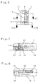
- Fig. 1
- eine Stirnansicht des Spannfutters nach der Erfindung, teilweise gebrochen dargestellt,
- Fig. 2
- der Schnitt II-II aus Fig. 1 in der dem Spannbackenwechsel dienenden Stellung der Keilstange,
- Fig. 3
- eine der Fig. 2 entsprechende Darstellung mit einer Keilstange in einer zum Beginnen der Verriegelung der Spannbacke befindlichen Position,
- Fig. 4
- eine der Fig. 2 entsprechende Darstellung mit einem vollständigen Verzahnungseingriff von Spannbacke und Keilstange,
- Fig. 5
- eine der Fig. 3 entsprechende Darstellung bei fehlender Spannbacke,
- Fig. 6
- der Schnitt VI-VI aus Fig. 4,
- Fig. 7
- der Schnitt VII-VII aus Fig. 6,
- Fig. 8
- der Schnitt VIII-VIII aus Fig. 6,
- Fig. 9
- eine der Fig. 6 entsprechende Darstellung einer Keilstange,
- Fig. 10
- der Schnitt X-X aus Fig. 9,
- Fig. 11
- der Schnitt XI-XI aus Fig. 9,
- Fig. 12
- eine Ansicht der Keilstange aus Fig. 9 aus Richtung des Pfeiles XII,
- Fig. 13
- eine Draufsicht auf den Sperrbolzen,
- Fig. 14
- eine Sicht auf den Sperrbolzen aus Richtung des Pfeiles XIV aus Fig. 13,
- Fig. 15
- eine Draufsicht auf das Rückstellglied,
- Fig. 16
- eine Sicht aus Richtung des Pfeiles XVI aus Fig. 15, und
- Fig. 17
- eine perspektivische Darstellung des Rückstellgliedes.
Claims (9)
- Spannfutter für Werkzeugmaschinen, insbesondere Drehmaschinen, mit einem mit dem Futterflansch (2) verbundenen Futterkörper (3), mit mehreren in radialen Führungsnuten (4) des Futterkörpers (3) angeordneten Spannbacken (5) und mit die Spannbacken (5) antreibenden, im Futterkörper (3) in Keilstangentaschen (6) quer zu den Führungsnuten (4) verschiebbaren Keilstangen (7), die zur Bildung einer Schrägverzahnung mit Zahnreihen (8) in entsprechende Zahnlücken (9) der Spannbacken (5) in Eingriff zu bringen sind, dadurch gekennzeichnet, daß in der Keilstange (7) in axialer Richtung des Futterkörpers (3) verstellbar ein Kontrollbolzen (10) und ein Sperrbolzen (11) gelagert sind, zu deren gemeinsamer, in entgegengesetzter Richtung erfolgender Verstellung ein Koppelglied (12) vorgesehen ist sowie eine eine Verstellung des Kontrollbolzens (10) in Richtung der Führungsnut (4) bewirkende Feder, und daß im Futterflansch (2) eine Rastaufnahme (14) ausgebildet ist, die den Sperrbolzen (11) aufnimmt, wenn der Kontrollbolzen (10) in die Führungsnut (4) eingreift.
- Spannfutter nach Anspruch 1, dadurch gekennzeichnet, daß ein Rückstellglied (21) vorgesehen ist, das bei der Bewegung der Keilstange (7) in die dem Spannbackenwechsel dienenden Stellung den Sperrbolzen (11) aus der Rastaufnahme (14) entfernt.
- Spannfutter nach Anspruch 2, dadurch gekennzeichnet, daß das Rückstellglied (21) in einer in der Keilstange (7) ausgebildeten Führungsaufnahme (22) angeordnet ist, eine Anlaufschräge zur Zusammenwirkung mit dem Sperrbolzen (11) aufweist, durch die Kraft einer Feder (24) in Richtung der Wand (30) der Keilstangentasche (6) verstellbar ist, und daß das Rückstellglied (21), wenn die Keilstange (7) sich in der dem Spannbackenwechsel dienenden Stellung befindet, über die Anlaufschräge (23) den Sperrbolzen (11) abstützt.
- Spannfutter nach Anspruch 3, dadurch gekennzeichnet, daß an dem Rückstellglied (21) eine zur Anlage an den Futterflansch (2) kommende Planfläche (31) ausgebildet ist.
- Spannfutter nach Anspruch 4, dadurch gekennzeichnet, daß die Planfläche (31) und eine an der dem Sperrbolzen (11) zugeordneten Anlaufschräge (23) zur Anlage kommende Rundfläche (25) an einem stirnseitig an dem Rückstellglied (21) angeordneten Hammerkopf (26) ausgebildet sind.
- Spannfutter nach einem der Ansprüche 1 bis 5, dadurch gekennzeichnet, daß der Kontrollbolzen (10) und der Sperrbolzen (11) an den freien Enden eines zweiarmigen, um eine parallel zur Führungsnut (4) liegende Achse (27) drehbaren Hebels (32) angeordnet sind.
- Spannfutter nach einem der Ansprüche 1 bis 6, dadurch gekennzeichnet, daß der Kontrollbolzen (10) und der Sperrbolzen (11) durch zwei Zahnstangen gebildet sind, die auf gegenüberliegenden Seiten eines um eine parallel zur Führungsnut (4) liegende Achse (27) drehbaren Zahnrades kämmen.
- Spannfutter nach Anspruch 6 oder 7, dadurch gekennzeichnet, daß die Achse (27) durch einen in eine Gewindebohrung der Keilstange (7) einschraubbaren Gewindestift (29) gebildet ist.
- Spannfutter nach einem der Ansprüche 1 bis 8, dadurch gekennzeichnet, daß an dem Kolben der Werkzeugmaschine ein Keilzahn (15) ausgebildet ist, der in eine an der Keilstange (7) ausgebildete Nut (16) eingreift, die zur Verschiebung der Keilstange (7) in Längsrichtung der Keilstangentasche (6) einen geneigt zur Futterachse (17) verlaufenden ersten Abschnitt (19) und zur Verstellung der Keilstange (7) durch einen Schlüssel zum Wechsel der Spannbacken (5) einen parallel zur Keilstangentasche (6) verlaufenden zweiten Abschnitt (20) aufweist, und daß der Keilzahn (15) sich bei in die Rastaufnahme (14) im Futterflansch (2) eingerücktem Sperrbolzen (11) zur Verhinderung einer axialen Verstellung des Kolbens in dem zweiten Abschnitt (20) befindet.
Priority Applications (1)
| Application Number | Priority Date | Filing Date | Title |
|---|---|---|---|
| EP00124175A EP1110648B1 (de) | 1999-12-24 | 2000-11-08 | Spannfutter für Werkzeugmaschinen |
Applications Claiming Priority (5)
| Application Number | Priority Date | Filing Date | Title |
|---|---|---|---|
| DE19962993A DE19962993A1 (de) | 1999-12-24 | 1999-12-24 | Spannfutter für Werkzeugmaschinen |
| DE19962993 | 1999-12-24 | ||
| EP00116929 | 2000-08-05 | ||
| EP00116929 | 2000-08-05 | ||
| EP00124175A EP1110648B1 (de) | 1999-12-24 | 2000-11-08 | Spannfutter für Werkzeugmaschinen |
Publications (2)
| Publication Number | Publication Date |
|---|---|
| EP1110648A1 true EP1110648A1 (de) | 2001-06-27 |
| EP1110648B1 EP1110648B1 (de) | 2002-07-10 |
Family
ID=26055910
Family Applications (1)
| Application Number | Title | Priority Date | Filing Date |
|---|---|---|---|
| EP00124175A Expired - Lifetime EP1110648B1 (de) | 1999-12-24 | 2000-11-08 | Spannfutter für Werkzeugmaschinen |
Country Status (5)
| Country | Link |
|---|---|
| EP (1) | EP1110648B1 (de) |
| AT (1) | ATE220358T1 (de) |
| DE (1) | DE50000268D1 (de) |
| ES (1) | ES2174791T3 (de) |
| TR (1) | TR200201161T3 (de) |
Families Citing this family (1)
| Publication number | Priority date | Publication date | Assignee | Title |
|---|---|---|---|---|
| CN109226516A (zh) * | 2018-11-23 | 2019-01-18 | 山东时风(集团)有限责任公司 | 一种汽车侧围翻边模具的整形结构 |
Citations (1)
| Publication number | Priority date | Publication date | Assignee | Title |
|---|---|---|---|---|
| DE19509976C1 (de) * | 1995-03-18 | 1996-08-08 | Smw Autoblok Spannsysteme Gmbh | Spannfutter |
-
2000
- 2000-11-08 TR TR2002/01161T patent/TR200201161T3/xx unknown
- 2000-11-08 DE DE50000268T patent/DE50000268D1/de not_active Expired - Fee Related
- 2000-11-08 EP EP00124175A patent/EP1110648B1/de not_active Expired - Lifetime
- 2000-11-08 ES ES00124175T patent/ES2174791T3/es not_active Expired - Lifetime
- 2000-11-08 AT AT00124175T patent/ATE220358T1/de not_active IP Right Cessation
Patent Citations (1)
| Publication number | Priority date | Publication date | Assignee | Title |
|---|---|---|---|---|
| DE19509976C1 (de) * | 1995-03-18 | 1996-08-08 | Smw Autoblok Spannsysteme Gmbh | Spannfutter |
Also Published As
| Publication number | Publication date |
|---|---|
| ATE220358T1 (de) | 2002-07-15 |
| EP1110648B1 (de) | 2002-07-10 |
| TR200201161T3 (tr) | 2002-06-21 |
| ES2174791T3 (es) | 2002-11-16 |
| DE50000268D1 (de) | 2002-08-14 |
Similar Documents
| Publication | Publication Date | Title |
|---|---|---|
| EP0185163B1 (de) | Bohrfutter | |
| DE3405511C1 (de) | Spannfutter,insbes.Bohrfutter | |
| DE9421725U1 (de) | Werkzeugfutter zur Ausstattung einer Drehmaschine, wie z.B. einer Bohrmaschine | |
| DE3712820C2 (de) | ||
| EP1572403B1 (de) | Kraftspannfutter und keilstange dafür | |
| DE60001337T2 (de) | Bohrfutter | |
| EP0870579B1 (de) | Spannstock | |
| CH675221A5 (de) | ||
| CH671719A5 (de) | ||
| DE19962993A1 (de) | Spannfutter für Werkzeugmaschinen | |
| EP1110648B1 (de) | Spannfutter für Werkzeugmaschinen | |
| EP0302187A1 (de) | Spanneinrichtung an Drehmaschinen mit einem Spannfutter | |
| EP1660262B1 (de) | Schnittstelle eines werkzeugs | |
| EP0195184A2 (de) | Spannbackenwechselvorrichtung | |
| DE3528943C1 (de) | Aufsatzbacke fuer Spannfutter | |
| EP0325728B1 (de) | Spannfutter für Gewindeschäfte | |
| DE3315661A1 (de) | Spannfutter fuer ein werkzeug zum schlagbohren | |
| DE1959770C3 (de) | Gewindeschneidfutter | |
| DE2736753A1 (de) | Spannfutter fuer drehmaschinen | |
| EP0612279B1 (de) | Spannvorrichtung zur verbindung von werkzeugkopf und werkzeughalter an werkzeugmaschinen | |
| DE1552207A1 (de) | Schnellspannfutter | |
| DE2916179A1 (de) | Spanneinrichtung, insbesondere maschinenschraubstock | |
| WO1993019892A1 (de) | Mehrfachaufspannvorrichtung | |
| DE10205791C1 (de) | Wechselhaltersystem für Werkzeuge | |
| DE3419154C2 (de) |
Legal Events
| Date | Code | Title | Description |
|---|---|---|---|
| PUAI | Public reference made under article 153(3) epc to a published international application that has entered the european phase |
Free format text: ORIGINAL CODE: 0009012 |
|
| AK | Designated contracting states |
Kind code of ref document: A1 Designated state(s): AT BE CH CY DE DK ES FI FR GB GR IE IT LI LU MC NL PT SE TR |
|
| AX | Request for extension of the european patent |
Free format text: AL;LT;LV;MK;RO;SI |
|
| 17P | Request for examination filed |
Effective date: 20010526 |
|
| GRAG | Despatch of communication of intention to grant |
Free format text: ORIGINAL CODE: EPIDOS AGRA |
|
| 17Q | First examination report despatched |
Effective date: 20011004 |
|
| GRAG | Despatch of communication of intention to grant |
Free format text: ORIGINAL CODE: EPIDOS AGRA |
|
| GRAH | Despatch of communication of intention to grant a patent |
Free format text: ORIGINAL CODE: EPIDOS IGRA |
|
| AKX | Designation fees paid |
Free format text: AT BE CH CY DE DK ES FI FR GB GR IE IT LI LU MC NL PT SE TR |
|
| GRAH | Despatch of communication of intention to grant a patent |
Free format text: ORIGINAL CODE: EPIDOS IGRA |
|
| GRAA | (expected) grant |
Free format text: ORIGINAL CODE: 0009210 |
|
| AK | Designated contracting states |
Kind code of ref document: B1 Designated state(s): AT BE CH CY DE DK ES FI FR GB GR IE IT LI LU MC NL PT SE TR |
|
| PG25 | Lapsed in a contracting state [announced via postgrant information from national office to epo] |
Ref country code: IE Free format text: LAPSE BECAUSE OF FAILURE TO SUBMIT A TRANSLATION OF THE DESCRIPTION OR TO PAY THE FEE WITHIN THE PRESCRIBED TIME-LIMIT Effective date: 20020710 Ref country code: GR Free format text: LAPSE BECAUSE OF FAILURE TO SUBMIT A TRANSLATION OF THE DESCRIPTION OR TO PAY THE FEE WITHIN THE PRESCRIBED TIME-LIMIT Effective date: 20020710 Ref country code: NL Free format text: LAPSE BECAUSE OF FAILURE TO SUBMIT A TRANSLATION OF THE DESCRIPTION OR TO PAY THE FEE WITHIN THE PRESCRIBED TIME-LIMIT Effective date: 20020710 Ref country code: FI Free format text: LAPSE BECAUSE OF FAILURE TO SUBMIT A TRANSLATION OF THE DESCRIPTION OR TO PAY THE FEE WITHIN THE PRESCRIBED TIME-LIMIT Effective date: 20020710 |
|
| REF | Corresponds to: |
Ref document number: 220358 Country of ref document: AT Date of ref document: 20020715 Kind code of ref document: T |
|
| REG | Reference to a national code |
Ref country code: GB Ref legal event code: FG4D Free format text: NOT ENGLISH |
|
| REG | Reference to a national code |
Ref country code: CH Ref legal event code: EP |
|
| GBT | Gb: translation of ep patent filed (gb section 77(6)(a)/1977) |
Effective date: 20020717 |
|
| REG | Reference to a national code |
Ref country code: IE Ref legal event code: FG4D Free format text: GERMAN |
|
| REF | Corresponds to: |
Ref document number: 50000268 Country of ref document: DE Date of ref document: 20020814 |
|
| PG25 | Lapsed in a contracting state [announced via postgrant information from national office to epo] |
Ref country code: PT Free format text: LAPSE BECAUSE OF FAILURE TO SUBMIT A TRANSLATION OF THE DESCRIPTION OR TO PAY THE FEE WITHIN THE PRESCRIBED TIME-LIMIT Effective date: 20021010 Ref country code: SE Free format text: LAPSE BECAUSE OF FAILURE TO SUBMIT A TRANSLATION OF THE DESCRIPTION OR TO PAY THE FEE WITHIN THE PRESCRIBED TIME-LIMIT Effective date: 20021010 Ref country code: DK Free format text: LAPSE BECAUSE OF FAILURE TO SUBMIT A TRANSLATION OF THE DESCRIPTION OR TO PAY THE FEE WITHIN THE PRESCRIBED TIME-LIMIT Effective date: 20021010 |
|
| PG25 | Lapsed in a contracting state [announced via postgrant information from national office to epo] |
Ref country code: LU Free format text: LAPSE BECAUSE OF NON-PAYMENT OF DUE FEES Effective date: 20021108 |
|
| REG | Reference to a national code |
Ref country code: ES Ref legal event code: FG2A Ref document number: 2174791 Country of ref document: ES Kind code of ref document: T3 |
|
| PG25 | Lapsed in a contracting state [announced via postgrant information from national office to epo] |
Ref country code: BE Free format text: LAPSE BECAUSE OF NON-PAYMENT OF DUE FEES Effective date: 20021130 Ref country code: CY Free format text: LAPSE BECAUSE OF FAILURE TO SUBMIT A TRANSLATION OF THE DESCRIPTION OR TO PAY THE FEE WITHIN THE PRESCRIBED TIME-LIMIT Effective date: 20021130 |
|
| NLV1 | Nl: lapsed or annulled due to failure to fulfill the requirements of art. 29p and 29m of the patents act | ||
| ET | Fr: translation filed | ||
| REG | Reference to a national code |
Ref country code: IE Ref legal event code: FD4D Ref document number: 1110648E Country of ref document: IE |
|
| PLBE | No opposition filed within time limit |
Free format text: ORIGINAL CODE: 0009261 |
|
| STAA | Information on the status of an ep patent application or granted ep patent |
Free format text: STATUS: NO OPPOSITION FILED WITHIN TIME LIMIT |
|
| BERE | Be: lapsed |
Owner name: *ROHM G.M.B.H. Effective date: 20021130 |
|
| PG25 | Lapsed in a contracting state [announced via postgrant information from national office to epo] |
Ref country code: MC Free format text: LAPSE BECAUSE OF NON-PAYMENT OF DUE FEES Effective date: 20030601 |
|
| 26N | No opposition filed |
Effective date: 20030411 |
|
| PGFP | Annual fee paid to national office [announced via postgrant information from national office to epo] |
Ref country code: FR Payment date: 20041104 Year of fee payment: 5 |
|
| PGFP | Annual fee paid to national office [announced via postgrant information from national office to epo] |
Ref country code: GB Payment date: 20041105 Year of fee payment: 5 |
|
| PG25 | Lapsed in a contracting state [announced via postgrant information from national office to epo] |
Ref country code: CH Free format text: LAPSE BECAUSE OF NON-PAYMENT OF DUE FEES Effective date: 20041130 Ref country code: LI Free format text: LAPSE BECAUSE OF NON-PAYMENT OF DUE FEES Effective date: 20041130 |
|
| REG | Reference to a national code |
Ref country code: CH Ref legal event code: PL |
|
| PG25 | Lapsed in a contracting state [announced via postgrant information from national office to epo] |
Ref country code: GB Free format text: LAPSE BECAUSE OF NON-PAYMENT OF DUE FEES Effective date: 20051108 |
|
| PGFP | Annual fee paid to national office [announced via postgrant information from national office to epo] |
Ref country code: AT Payment date: 20051130 Year of fee payment: 6 |
|
| GBPC | Gb: european patent ceased through non-payment of renewal fee |
Effective date: 20051108 |
|
| PG25 | Lapsed in a contracting state [announced via postgrant information from national office to epo] |
Ref country code: FR Free format text: LAPSE BECAUSE OF NON-PAYMENT OF DUE FEES Effective date: 20060731 |
|
| REG | Reference to a national code |
Ref country code: FR Ref legal event code: ST Effective date: 20060731 |
|
| PG25 | Lapsed in a contracting state [announced via postgrant information from national office to epo] |
Ref country code: AT Free format text: LAPSE BECAUSE OF NON-PAYMENT OF DUE FEES Effective date: 20061108 |
|
| PGFP | Annual fee paid to national office [announced via postgrant information from national office to epo] |
Ref country code: DE Payment date: 20081110 Year of fee payment: 9 |
|
| PGFP | Annual fee paid to national office [announced via postgrant information from national office to epo] |
Ref country code: ES Payment date: 20081029 Year of fee payment: 9 |
|
| PGFP | Annual fee paid to national office [announced via postgrant information from national office to epo] |
Ref country code: IT Payment date: 20081127 Year of fee payment: 9 |
|
| PG25 | Lapsed in a contracting state [announced via postgrant information from national office to epo] |
Ref country code: DE Free format text: LAPSE BECAUSE OF NON-PAYMENT OF DUE FEES Effective date: 20100601 |
|
| REG | Reference to a national code |
Ref country code: ES Ref legal event code: FD2A Effective date: 20110301 |
|
| PG25 | Lapsed in a contracting state [announced via postgrant information from national office to epo] |
Ref country code: IT Free format text: LAPSE BECAUSE OF NON-PAYMENT OF DUE FEES Effective date: 20091108 |
|
| PG25 | Lapsed in a contracting state [announced via postgrant information from national office to epo] |
Ref country code: ES Free format text: LAPSE BECAUSE OF NON-PAYMENT OF DUE FEES Effective date: 20110228 |
|
| PG25 | Lapsed in a contracting state [announced via postgrant information from national office to epo] |
Ref country code: TR Free format text: LAPSE BECAUSE OF NON-PAYMENT OF DUE FEES Effective date: 20100921 Ref country code: ES Free format text: LAPSE BECAUSE OF NON-PAYMENT OF DUE FEES Effective date: 20081109 |
|
| PGFP | Annual fee paid to national office [announced via postgrant information from national office to epo] |
Ref country code: TR Payment date: 20081031 Year of fee payment: 9 |
|
| PG25 | Lapsed in a contracting state [announced via postgrant information from national office to epo] |
Ref country code: TR Free format text: LAPSE BECAUSE OF NON-PAYMENT OF DUE FEES Effective date: 20091108 |