EP1110009B1 - Rücklaufbremse - Google Patents
Rücklaufbremse Download PDFInfo
- Publication number
- EP1110009B1 EP1110009B1 EP99946165A EP99946165A EP1110009B1 EP 1110009 B1 EP1110009 B1 EP 1110009B1 EP 99946165 A EP99946165 A EP 99946165A EP 99946165 A EP99946165 A EP 99946165A EP 1110009 B1 EP1110009 B1 EP 1110009B1
- Authority
- EP
- European Patent Office
- Prior art keywords
- braking
- brake
- friction
- expanding ring
- running
- Prior art date
- Legal status (The legal status is an assumption and is not a legal conclusion. Google has not performed a legal analysis and makes no representation as to the accuracy of the status listed.)
- Expired - Lifetime
Links
- 230000000903 blocking effect Effects 0.000 claims description 15
- 239000000463 material Substances 0.000 claims description 14
- 230000000694 effects Effects 0.000 claims description 12
- 230000008602 contraction Effects 0.000 claims description 3
- 239000013013 elastic material Substances 0.000 claims description 3
- 238000009434 installation Methods 0.000 claims description 3
- 230000003321 amplification Effects 0.000 claims 2
- 238000003199 nucleic acid amplification method Methods 0.000 claims 2
- 230000004913 activation Effects 0.000 claims 1
- 230000002441 reversible effect Effects 0.000 description 35
- 230000007480 spreading Effects 0.000 description 22
- 238000003892 spreading Methods 0.000 description 22
- 240000006829 Ficus sundaica Species 0.000 description 5
- 238000010276 construction Methods 0.000 description 4
- 241001295925 Gegenes Species 0.000 description 3
- 239000002360 explosive Substances 0.000 description 3
- 238000000034 method Methods 0.000 description 3
- 230000008569 process Effects 0.000 description 3
- 238000009423 ventilation Methods 0.000 description 3
- 238000004804 winding Methods 0.000 description 3
- 229910000831 Steel Inorganic materials 0.000 description 2
- HCHKCACWOHOZIP-UHFFFAOYSA-N Zinc Chemical compound [Zn] HCHKCACWOHOZIP-UHFFFAOYSA-N 0.000 description 2
- XAGFODPZIPBFFR-UHFFFAOYSA-N aluminium Chemical compound [Al] XAGFODPZIPBFFR-UHFFFAOYSA-N 0.000 description 2
- 229910052782 aluminium Inorganic materials 0.000 description 2
- 238000005516 engineering process Methods 0.000 description 2
- 238000001746 injection moulding Methods 0.000 description 2
- 230000007246 mechanism Effects 0.000 description 2
- 239000010959 steel Substances 0.000 description 2
- 229910052725 zinc Inorganic materials 0.000 description 2
- 239000011701 zinc Substances 0.000 description 2
- 241001136792 Alle Species 0.000 description 1
- 240000003517 Elaeocarpus dentatus Species 0.000 description 1
- 206010041953 Staring Diseases 0.000 description 1
- 230000009471 action Effects 0.000 description 1
- 238000004873 anchoring Methods 0.000 description 1
- 230000005540 biological transmission Effects 0.000 description 1
- 238000000576 coating method Methods 0.000 description 1
- 230000007423 decrease Effects 0.000 description 1
- 238000009826 distribution Methods 0.000 description 1
- 210000003746 feather Anatomy 0.000 description 1
- 239000006260 foam Substances 0.000 description 1
- 239000002655 kraft paper Substances 0.000 description 1
- 238000004519 manufacturing process Methods 0.000 description 1
- 230000036316 preload Effects 0.000 description 1
- 230000002028 premature Effects 0.000 description 1
- 238000003825 pressing Methods 0.000 description 1
- 230000002035 prolonged effect Effects 0.000 description 1
- 239000011343 solid material Substances 0.000 description 1
- 230000007704 transition Effects 0.000 description 1
- 239000002699 waste material Substances 0.000 description 1
Images



Classifications
-
- F—MECHANICAL ENGINEERING; LIGHTING; HEATING; WEAPONS; BLASTING
- F16—ENGINEERING ELEMENTS AND UNITS; GENERAL MEASURES FOR PRODUCING AND MAINTAINING EFFECTIVE FUNCTIONING OF MACHINES OR INSTALLATIONS; THERMAL INSULATION IN GENERAL
- F16D—COUPLINGS FOR TRANSMITTING ROTATION; CLUTCHES; BRAKES
- F16D51/00—Brakes with outwardly-movable braking members co-operating with the inner surface of a drum or the like
- F16D51/02—Brakes with outwardly-movable braking members co-operating with the inner surface of a drum or the like shaped as one or more circumferential band
-
- G—PHYSICS
- G05—CONTROLLING; REGULATING
- G05G—CONTROL DEVICES OR SYSTEMS INSOFAR AS CHARACTERISED BY MECHANICAL FEATURES ONLY
- G05G1/00—Controlling members, e.g. knobs or handles; Assemblies or arrangements thereof; Indicating position of controlling members
- G05G1/08—Controlling members for hand actuation by rotary movement, e.g. hand wheels
- G05G1/10—Details, e.g. of discs, knobs, wheels or handles
- G05G1/12—Means for securing the members on rotatable spindles or the like
-
- F—MECHANICAL ENGINEERING; LIGHTING; HEATING; WEAPONS; BLASTING
- F16—ENGINEERING ELEMENTS AND UNITS; GENERAL MEASURES FOR PRODUCING AND MAINTAINING EFFECTIVE FUNCTIONING OF MACHINES OR INSTALLATIONS; THERMAL INSULATION IN GENERAL
- F16D—COUPLINGS FOR TRANSMITTING ROTATION; CLUTCHES; BRAKES
- F16D51/00—Brakes with outwardly-movable braking members co-operating with the inner surface of a drum or the like
- F16D51/02—Brakes with outwardly-movable braking members co-operating with the inner surface of a drum or the like shaped as one or more circumferential band
- F16D51/04—Brakes with outwardly-movable braking members co-operating with the inner surface of a drum or the like shaped as one or more circumferential band mechanically actuated
-
- F—MECHANICAL ENGINEERING; LIGHTING; HEATING; WEAPONS; BLASTING
- F16—ENGINEERING ELEMENTS AND UNITS; GENERAL MEASURES FOR PRODUCING AND MAINTAINING EFFECTIVE FUNCTIONING OF MACHINES OR INSTALLATIONS; THERMAL INSULATION IN GENERAL
- F16D—COUPLINGS FOR TRANSMITTING ROTATION; CLUTCHES; BRAKES
- F16D59/00—Self-acting brakes, e.g. coming into operation at a predetermined speed
-
- G—PHYSICS
- G05—CONTROLLING; REGULATING
- G05G—CONTROL DEVICES OR SYSTEMS INSOFAR AS CHARACTERISED BY MECHANICAL FEATURES ONLY
- G05G1/00—Controlling members, e.g. knobs or handles; Assemblies or arrangements thereof; Indicating position of controlling members
- G05G1/08—Controlling members for hand actuation by rotary movement, e.g. hand wheels
-
- F—MECHANICAL ENGINEERING; LIGHTING; HEATING; WEAPONS; BLASTING
- F16—ENGINEERING ELEMENTS AND UNITS; GENERAL MEASURES FOR PRODUCING AND MAINTAINING EFFECTIVE FUNCTIONING OF MACHINES OR INSTALLATIONS; THERMAL INSULATION IN GENERAL
- F16D—COUPLINGS FOR TRANSMITTING ROTATION; CLUTCHES; BRAKES
- F16D69/00—Friction linings; Attachment thereof; Selection of coacting friction substances or surfaces
- F16D2069/004—Profiled friction surfaces, e.g. grooves, dimples
Definitions
- the invention relates Reverse brakes, which are also known as brake drives can be and in many areas of Technology can be used, such as. B. as adjusting and fixing devices for machines, medical devices and apparatus, sports and household appliances, Control mechanisms, for seating and other furniture, in vehicles, aircraft, Car seats etc.
- These reverse brakes can both by a handwheel 6 and a shift lever (6a in Fig. 5) or by not shown electrical, pneumatic, hydraulic or any other switching or control elements are operated.
- Previous return brakes have multi-cylindrical cylindrical brake body Coil springs that extend along a stationary drum cylinder circular pressure on one of the two spring ends in a stationary Drum cylinder (e.g. counterclockwise) from one spring turn to the other widen gradually until all turns are gradually against the stationary drum are jammed and block further twisting in the same direction.
- a circular, i.e. circular pulling force at the other end of the same brake spring understandably only with one slip compared to the previous one Circular compressive force at the other end of the spring
- the individual spring windings step by step rewound on a smaller cylinder outer diameter of the spring and that Jamming or blocking against twisting of the spring and thus one Eventual output shaft only gradually with an undesirable slip path To get picked up.
- Shoe brakes include the disadvantage that their cylindrical friction surfaces are constant rigid in diameter and in curvature with the housing inner cylinder curvature a real, full, evenly lying on the entire brake circumference, cannot achieve specific pressure force or guarantee it over a long period. Out For this reason, almost all shoe brakes need an additional, compressible one Material (the brake pads) between the shoe brake surface and the Have drum inner cylinder braking surface, even with prolonged use need to be replaced.
- a reverse brake with a a spreading ring, self-energizing brake the Blockage via a radial contraction of the expansion ring is optionally reversible, known.
- This reverse brake includes in particular a brake drum on which the spreader ring under Voltage is applied, with the expansion ring through its ends a fixed stop pressed against the brake drum becomes. By pulling the ends of the expansion ring together the braking effect or blocking of the expansion ring is released, so that the brake drum attached to a shaft is freely rotatable.
- the object of the invention is to provide return brakes that are simple and Inexpensive way due to their construction and optimal brake pressure distribution Plastic, zinc or aluminum injection molding, i.e. made of less strong material (parts 1 to 6a) can be performed and both by a handwheel (6) and by a Shift lever (6a of FIG. 5) or by not shown electrical, pneumatic, hydraulic, magnetic or any other switching or control elements from the Primary or drive side "with the drive side, e.g. shaft 3" in both directions, i.e. also against a locking or braking force, with a low star Slip between primary rotation (adjustment or actuation) and secondary Backstop or movement, e.g. on an input or output shaft 3 and can be fixed.
- each rotation of the start and Output shafts can be set as quickly and at any time depending on the design and setting severely slowed down or totally blocked and released again.
- the disadvantages or Weaknesses of reverse brakes and freewheel brakes according to the current status of Technology are avoided by the present invention.
- the reverse brake is in the free interior as an exemplary embodiment in FIGS. 1 to 4 of a usually hollow handwheel (part 6) installed, for example, too an actuation or adjustment of a car or office armchair or any Machine or any device can be mounted or with a soft one automatic, braked or blocked against reverse or rewind should be performed.
- Such a handwheel (part 6) or such an adjustment lever (part 6a in FIG. 5) or also only the brake drive alone (with or without other actuators) can be without additional ventilation of a brake or freewheel or other brake or blocking can be adjusted in both directions, taking the shaft (part 3) with it.
- the handwheel or the lever or actuating element for the anti-skid brake it automatically brakes or locks itself; i.e. driven by the Shaft 3 can be the reverse brake (depending on the setting and / or construction. Preload, material application, etc.) after releasing an adjusting force a primary adjustment (using the handwheel, lifting, etc.) is difficult or impossible braked turn back the set rotary movement retroactively.
- the reverse brake can also be used in any construction on one any point of an input or output shaft (against external torque supported by the environment or a cable, a spoke or other Anchoring) so that the primary adjustment torque e.g. by a second (not shown on an extension of the first shaft 3), not shown, on the same Axial hollow shaft or articulated at an angle to the main axis Adjustment shaft, but also e.g. through a rope spool and Bowden cables, gear or other drive mechanisms within a device, apparatus, furniture, vehicle etc. (primarily thus to adjust), with the abortionate or driven, outgoing Wave 3 can be adjusted with the primary setting. Conversely, i.e. secondary, However, this shaft 3 cannot (or depending on the setting only more or less difficult) turn this brake drive.
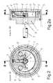
- Fig. 1 shows in section A-A through Fig. 1a, a housing 1 with a cylindrical inner surface, which as Friction (or braking) surface 5 is used and the open single expansion ring 2, its has cylindrical friction surface 5 on the outside, receives.
- the default Outside diameter of the expansion ring 2 has a larger one when not installed Outside diameter as the cylindrical inner friction surface 5 of the housing 1.
- the handwheel 6 can then reverse the blocking or braking effect Order via the expansion ring 2, the abutment part 4 ', the driver pin 4 and the Cancel wave 3 and allow all mechanics, i.e. the brake drive, the Twisting and adjustment in both directions of rotation (also against a blockage).
- Fig. 1 a shows section B-B through the center of the embodiment of FIG. 1.
- Das Circular pull handwheel 6 is slipped over the housing 1 and with molded snap-in lugs 7 secured against being pulled off.
- An embodiment not shown would be e.g. an expanding material like a rubber, Foam, a plastic, an air cushion, gas springs etc., which in the expansion ring for Increase in the spreading force can be inserted.
- Fig. 2a is also an example of a type of attachment of the entire reverse brake shown through the bottom of the housing 1 with countersunk screws 8, the Representation of wave 3 is interrupted
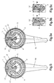
- Fig. 3 shows a further reverse brake with a double expansion ring 2, the inner ring additionally applies a spreading force to the friction surface 5.
- a and b are two examples of the design of the Friction or braking surfaces 5 shown.
- the ripple of both friction surfaces 5, for example can have the same or a different structure both on the housing 1 and on have the expansion ring 2 and be microfine or coarse and of different depths.
- the difference between the two examples is that in variant a the swell is symmetrical is even, so that when braking and when adjusting in both directions of rotation same resistance is opposed, with variant b the swell is increasing steeper than in decline, so that when braking and adjusting in one direction greater and less resistance in the other direction.
- Fig. 3 also shows brake start aids 12 and 12a, which are attached only once and only in a direction of rotation after the ventilation process, the spreading of the spreading element (like a Trim oars on ships) when they are on the other, not pushed Spread ring front side (by slightly protruding over the brake cylinder or by Special brake material).
- brake start aids 12 and 12a which are attached only once and only in a direction of rotation after the ventilation process, the spreading of the spreading element (like a Trim oars on ships) when they are on the other, not pushed Spread ring front side (by slightly protruding over the brake cylinder or by Special brake material).
- Fig. 5 shows a reverse brake with double expansion ring 2 and a despreading pivot lever 6a, which has two expansion pins 6 ', 6 "in one piece or firmly connected to it Shaft 3 has a driver 4 (connected to it in one piece or loosely for engagement), whose end engages in the opening of the expansion ring 2 and one on the shaft retroactive torque transmits to a spreading lever 10.
- the double expansion ring 2 is the two in their Distance to each other and to the swivel lift 6a, e.g. through one-piece execution of all three elements, fixed expansion pin 6 'which swivels with the swivel lever 6a and 6 "compressed to a smaller outside diameter, which increases the spreading force and Braking effect is canceled or reduced.
- the swivel lever always swings the expansion pin 6 'or 6 "as a fulcrum, which is on the same pivoting direction of the Lever sits.
- the pivot lever 6a When the pivot lever 6a is released, it spreads immediately the expansion ring 2, reinforced or not reinforced e.g. through a Expansion amplifier lever 10 and brakes or blocks, depending on the design, design, Intent, the materials used, etc., a turning back by the output shaft 3 or a counter torque.
- the pivot lever 6a can also be slipped over the entire reverse brake Handwheel 6 without lever - as shown in Figures 1 and 1a, 2 and 2a and 3 and 4 be when between the inner cylinder of the handwheel 6 and the Outer cylinder of the housing 1 enough play for easy pivoting around one of the two pins 6 'or 6 "- instead of twisting around the central center - is left.
- FIGS. 5b and 5c each show an expansion amplifier lever 10 'which is in contact with its Pivot part can rotate about its pivot point M if from the shaft 3 over their driver pin 4 presses a counter torque from the output side.
- the Spreading amplifier lever in Fig. 5b thus has e.g. already the spreading amplifier 10 ' twisted and its eccentric circle part surface also spreads the counter surface the same expansion ring 2 at the point of contact of the tangent T and presses additionally the end of the expansion ring 2 with this transmission lever 10 ' its friction surface on the housing cylinder surface.
- Fig. 5c shows that the Spreading amplifier 10 'again in the reverse order around the pivot point M is turned back when the expansion ring 2 (as described in Fig. 5a) by a Gear ratio swivel 6a despread, i.e. again to a smaller diameter is compressed.
- FIGS. 6 and 6a show an elastic expansion ring 2b made of a somewhat elastic material, its outer cylinder in diameter as in the existing spreading rings 2 and 2a the assembly is larger than the inside diameter of the cylinder of the housing 1.
- After assembly i.e. after squeezing this elastic expansion ring into the housing there is also already a "self-expansion or self-braking force", which in a Direction of rotation is smaller and much larger in the other.
- One or more on or just below Brake cylinder circumference of the elastic expansion ring 2b arranged circular shrink rings 13 can be tied together and shortened their circumference, e.g. with help of the illustrated pivot lever 6a their own diameter and Reduce the elastic expansion ring diameter. Through this is also the braking or Blocking force of the elastic expansion ring 2b reduced and an adjustment of the whole Reverse brake together with the anti-theft shaft 3 anchored in the expansion ring 2b in both Direction of rotation and also possible against the segment sections and blocking force.
- the reverse brake can be used with or without turning the spreading ring or rings in both Brakes and / or blocks the direction of rotation and only slides back even in the event of an overload but start again without a break.
- the reverse brake or only the drive shaft can be directly or indirectly through active elements lifting, tensioning, pulling, pressing, arching, adjusting other parts and everything again fix or block or block.
Landscapes
- Engineering & Computer Science (AREA)
- General Engineering & Computer Science (AREA)
- Mechanical Engineering (AREA)
- Physics & Mathematics (AREA)
- General Physics & Mathematics (AREA)
- Automation & Control Theory (AREA)
- Braking Arrangements (AREA)
Description
- Fig. 1
- ein Ausführungsbeispiel einer Rücklaufbremse im Schnitt A-A gemäß Fig. 1a,
- Fig. 1a
- das Ausführungsbeispiel gemäß Fig. 1 im Schnitt B-B der Fig. 1,
- Fig. 2
- ein weiteres Ausführungsbeispiel einer Rücklaufbremse im Schnitt A-A gemäß Fig. 2a,
- Fig. 2a
- das Ausführungsbeispiel gemäß Fig. 2 im Schnitt B-B der Fig. 2,
- Fig. 3
- ein drittes Ausführungsbeispiel einer Rücklaufbremse im Schnitt A-A der Fig. 4,
- Fig. 3 a, b
- Details aus Fig. 3 in vergrößerter Darstellung.
- Fig. 4
- das Ausführungsbeispiel gemäß Fig. 3 im Schnitt B-B der Fig. 3,
- Fig. 5 a,b,c
- ein viertes Ausführungsbeispiel einer Rücklaufbremse mit vergrößert dargestellten Details in verschiedenen Arbeitsstellungen,
- Fig. 6
- ein fünftes Ausführungsbeispiel einer Rücklaufbremse im Schnitt A-A der Fig. 6a,
- Fig. 6a
- das Ausführungsbeispiel gemäß Fig. 6 im Schnitt B-B der Fig. 6.
Claims (11)
- Rücklaufbremse mit einer mit einer Abtriebswelle versehenen Bremstrommel (1), in deren Innenraum ein vor dem Einbau im Durchmesser größerer Spreizring (2) angeordnet ist, welcher nach dem Einbau durch seine Expansionskraft an einer an seiner Außenseite vorgesehenen Reibfläche (5) eine Eigenexpansionsreibung gegenuber einer an einer Innenfläche der Bremstrommel (1) vorgesehenen weiteren Reibfläche (5) gegen Verdrehen aufweist,
wobei die Bremstrommel (1) gegen ein Verdrehen gesichert ist und wobei bei Auftreten eines Rücklaufdrehmomentes an der Abtriebswelle (3) über deren Mitnehmerzapfen (4) und dessen zirkulare Schubkraft auf eine der beiden Stimseiten des Spreizringes (2) eine zusätzliche Spreiz- und Bremsverstärkung bis zu einer eventuellen Totalsperre aufgebracht wird, die durch Verdrehen des Primärhandrades (6) oder entspreizschwenkhebels (6a) auf der Eingangsseite, mit Hilfe der beiden fest an ihnen angebrachten Entspreizzapfen (6' und 6") wieder durch eine zirkulare Zugkraft auf die gegenüberliegende Stirnseite des Spreizringes (2) diesen derart zusammenzieht, daß die Bremsreibung oder gar Blockade wieder aufgehoben und eine Verstellung sowie Fixierung der ganzen Rücklaufbremse in beiden Drehnchtungen auf der Eingangssowie Ausgangsseite jederzeit wieder möglich ist. - Rücklaufbremse nach Anspruch 1, dadurch gekennzeichnet, daß die Expansionskraft des oder mehrerer Spreizringe (2) durch kompressible Spreizmittel (9, 9', 9") verstärkt wird.
- Rücklaufbremse nach Anspruch 1 oder 2, dadurch gekennzeichnet, daß der Spreizring (2) aus zwei ineinander angeordneten Spreizringen (2, 2a) besteht.
- Rücklaufbremse nach einem der Ansprüche 1 bis 3, dadurch gekennzeichnet, daß die Reibflächen (5) zylindrisch oder kegelig ausgeführt sind.
- Rücklaufbremse nach einem der Ansprüche 1 bis 4, dadurch gekennzeichnet, daß die Reibflächen (5) in der Bremstrommei (1) und an de Außenseite des Spreizringes (2) in Drehrichtung synchron zur Erzielung eines gleichgroßen oder je nach Drehrichtung verschieden großen Brems-oder Reibwiderstands eine symmetrische bzw. asymmetrische mikro- oder makrowellenförmige Reiboberfläche aufweisen.
- Rücklaufbremse nach einem der Ansprüche 1 bis 5, dadurch gekennzeichnet, daß die Bremsflächen (5) zur Erhöhung der Bremskraft kreisrunde Keilnuten und Keilvorsprünge mit Keilnuten und kreisrunde Keilrippen aufweisen.
- Rücklaufbremse nach einem der Ansprüche 1 bis 6, dadurch gekennzeichnet, daß der Spreizring (2b) mindestens teilweise aus leicht elastischem Material mit großem Reibwiderstand hergestellt ist und/oder mit durch Einschnitte (14) und durch Verkeilen der verbleibenden Segmente zum zusätzlichen Bremsen oder Blockieren versehen ist
- Rücklaufbremse nach einem der Ansprüche 1 bis 7, dadurch gekennzeichnet, daß ein oder mehrere Teile der Spreizringreibfläche (5) durch Einschnitte (12) oder Vorsprünge gegenüber der übrigen Außenseite der Spreizrings vorstehen und zuerst bremsend wirken.
- Rücklaufbremse nach einem der bisherigen Ansprüche 1 bis 8, dadurch gekennzeichnet, daß, auch um bei kleinerer Spreizkraft eine totale Rücklaufsperre zu erreichen, die Reibfläche (5) der Bremstrommel (1) oder die Reibfläche (5) des Spreizrings (2) zur Gänze oder teilweise mit einem Material mit größerem Reibungswiderstand versehen sind.
- Rücklaufbremse nach etnem der Ansprüche 1 bis 9, dadurch gekennzeichnet, daß mit dem Handrad (6) oder dem Schwenkhebel (6a) zwei Zapfen (6'und 6") verbunden sind, obei bei Betätigung des Handrades, das mit vergrößertem Zwischenraum zur Bremstrommel (1) angeordnet ist, bzw. des Schwenkhebels (6a), diese je nach Drehrichtung um einen der beiden Zapfen (6' oder 6") derart gedreht oder geschwenkt werden, daß durch den gleichbleibenden Abstand der beiden Zapfen zwangsläufig der Spreizring (2) zusammengezogen und dadurch die Spreizkraft sowie Reibung an der Reibfiäche (5) durch Verkleinerung des Spreizringdurchmessers verringert oder aufgehoben wird.
- Rücklaufbremse nach einem der Ansprüche 1 bis 10, dadurch gekennzeichnet, daß ein zusätzlicher Spreizverstärkerhebel (10 oder 10') zur Verstärkung der Spreizkraft des Spreizringes bei Auftreten einer Rückdrehkraft durch die Welle (3) und zu einer Rücklaufbremsung, je nach Planung und Einstellung des Bremsantriebes, bis zu einer Rücklaufsperre, vorgesehen ist.
Priority Applications (1)
| Application Number | Priority Date | Filing Date | Title |
|---|---|---|---|
| AT99946165T ATE262121T1 (de) | 1998-09-11 | 1999-09-13 | Rücklaufbremse |
Applications Claiming Priority (3)
| Application Number | Priority Date | Filing Date | Title |
|---|---|---|---|
| AT153798 | 1998-09-11 | ||
| AT153798 | 1998-09-11 | ||
| PCT/EP1999/006747 WO2000015973A1 (de) | 1998-09-11 | 1999-09-13 | Bremsantrieb |
Publications (2)
| Publication Number | Publication Date |
|---|---|
| EP1110009A1 EP1110009A1 (de) | 2001-06-27 |
| EP1110009B1 true EP1110009B1 (de) | 2004-03-17 |
Family
ID=3515614
Family Applications (1)
| Application Number | Title | Priority Date | Filing Date |
|---|---|---|---|
| EP99946165A Expired - Lifetime EP1110009B1 (de) | 1998-09-11 | 1999-09-13 | Rücklaufbremse |
Country Status (11)
| Country | Link |
|---|---|
| US (2) | US6655520B2 (de) |
| EP (1) | EP1110009B1 (de) |
| JP (1) | JP2002525506A (de) |
| KR (1) | KR20010075039A (de) |
| CN (1) | CN1317076A (de) |
| AU (1) | AU760338B2 (de) |
| BR (1) | BR9913597A (de) |
| CA (1) | CA2343514A1 (de) |
| DE (1) | DE59908905D1 (de) |
| WO (1) | WO2000015973A1 (de) |
| ZA (1) | ZA200102723B (de) |
Families Citing this family (15)
| Publication number | Priority date | Publication date | Assignee | Title |
|---|---|---|---|---|
| WO2001077325A1 (fr) * | 2000-04-12 | 2001-10-18 | Takeda Chemical Industries, Ltd. | Nouvelle proteine de recepteur couple aux proteines g et adn de celle-ci |
| DE20017940U1 (de) | 2000-10-19 | 2000-12-28 | MAP Medizintechnik für Arzt und Patient GmbH & Co KG, 82152 Planegg | Atemmaske zur Zufuhr eines Atemgases zu einem Maskenanwender sowie Ableitungseinrichtung zur Ableitung von Atemgas |
| WO2003035156A2 (de) | 2001-10-22 | 2003-05-01 | Map Medizin-Technologie Gmbh | Atemmaskenanordnung sowie applikationsvorrichtung und stirnauflageeinrichtung hiervon |
| DE10151984C5 (de) | 2001-10-22 | 2008-07-17 | Map Medizin-Technologie Gmbh | Applikationsvorrichtung für eine Atemmaskenanordnung |
| DE10160684A1 (de) * | 2001-12-11 | 2003-06-18 | Bosch Gmbh Robert | Lastdrehmomentsperre |
| US7182196B2 (en) * | 2002-02-06 | 2007-02-27 | Intier Automotive Inc. | Two way locking rotary drive clutch assembly |
| DE10318894A1 (de) * | 2003-04-22 | 2004-11-11 | Brose Fahrzeugteile Gmbh & Co. Kommanditgesellschaft, Coburg | Beidseitig wirkender Antrieb |
| KR101394124B1 (ko) * | 2010-03-29 | 2014-05-14 | 주식회사 만도 | Dih 브레이크 장치 |
| US7861840B1 (en) * | 2010-08-10 | 2011-01-04 | Winzeler Gear, Inc. | Anti-back drive system |
| CN104665318A (zh) * | 2015-03-18 | 2015-06-03 | 常州市莱特气弹簧有限公司 | 升降不旋转气压棒 |
| CN104863993A (zh) * | 2015-05-20 | 2015-08-26 | 魏伯卿 | 双螺纹套筒锥面磨擦弹压自紧式紧急刹车包 |
| MX2020001803A (es) | 2017-08-21 | 2020-07-13 | Valmont Industries | Sistema y metodo para proporcionar el frenado del eje de transmision para las maquinas de riego. |
| EP3575001B3 (de) * | 2018-05-28 | 2022-09-14 | Bühler AG | Walzenpakete für vermahlungsvorrichtungen, vermahlungsvorrichtungen und verfahren |
| CN109712513B (zh) * | 2019-03-06 | 2021-02-02 | 滨州学院 | 一种地理学习用多用途地球仪 |
| JP7161625B2 (ja) | 2020-09-25 | 2022-10-26 | 有限会社T.P.P. | 摩擦クラッチのプレッシャープレート装置 |
Family Cites Families (12)
| Publication number | Priority date | Publication date | Assignee | Title |
|---|---|---|---|---|
| US905912A (en) * | 1907-03-02 | 1908-12-08 | Oscar F Ehrle | Steering-gear. |
| US2845156A (en) * | 1953-12-16 | 1958-07-29 | Gen Electric | Torque transmission and automatic braking means for clothes washers and the like |
| US3146868A (en) * | 1961-05-26 | 1964-09-01 | Bates Mfg Co | Rotary card index with brake |
| US3307663A (en) * | 1965-02-08 | 1967-03-07 | Emerson Electric Co | Anti-creep device for variable ratio transmissions or the like |
| US3447643A (en) * | 1967-11-21 | 1969-06-03 | Ingersoll Rand Co | Reversible one-way brake |
| US3587796A (en) | 1969-09-15 | 1971-06-28 | Duff Norton Co | Self-locking transmission mechanism |
| US3722641A (en) * | 1971-09-16 | 1973-03-27 | United Aircraft Corp | No back actuator system |
| FR2281519A1 (fr) | 1974-08-08 | 1976-03-05 | Tissmetal Lionel Dupont | Dispositif antiretour a double effet |
| US4591029A (en) * | 1984-08-17 | 1986-05-27 | Da Foe John P | Load actuating braking apparatus |
| SE445248B (sv) * | 1984-10-18 | 1986-06-09 | Bo Granbom | Bromsanordning vid anordningar for omvandling av en roterande rorelse till en linjer rorelse |
| US5007511A (en) * | 1989-11-02 | 1991-04-16 | Dana Corporation | Bi-directional back stopping clutch |
| US5779383A (en) * | 1996-03-28 | 1998-07-14 | Mccallum; Dennis L. | Braked mechanical joint assembly |
-
1999
- 1999-09-13 CA CA002343514A patent/CA2343514A1/en not_active Abandoned
- 1999-09-13 CN CN99810782A patent/CN1317076A/zh active Pending
- 1999-09-13 AU AU58626/99A patent/AU760338B2/en not_active Ceased
- 1999-09-13 EP EP99946165A patent/EP1110009B1/de not_active Expired - Lifetime
- 1999-09-13 JP JP2000570475A patent/JP2002525506A/ja active Pending
- 1999-09-13 KR KR1020017003132A patent/KR20010075039A/ko not_active Abandoned
- 1999-09-13 DE DE59908905T patent/DE59908905D1/de not_active Expired - Fee Related
- 1999-09-13 BR BR9913597-3A patent/BR9913597A/pt unknown
- 1999-09-13 WO PCT/EP1999/006747 patent/WO2000015973A1/de not_active Ceased
-
2001
- 2001-03-09 US US09/802,516 patent/US6655520B2/en not_active Expired - Lifetime
- 2001-04-03 ZA ZA200102723A patent/ZA200102723B/en unknown
-
2003
- 2003-10-13 US US10/684,236 patent/US20040124061A1/en not_active Abandoned
Also Published As
| Publication number | Publication date |
|---|---|
| JP2002525506A (ja) | 2002-08-13 |
| KR20010075039A (ko) | 2001-08-09 |
| BR9913597A (pt) | 2001-05-22 |
| EP1110009A1 (de) | 2001-06-27 |
| AU5862699A (en) | 2000-04-03 |
| US6655520B2 (en) | 2003-12-02 |
| DE59908905D1 (de) | 2004-04-22 |
| US20010042670A1 (en) | 2001-11-22 |
| CN1317076A (zh) | 2001-10-10 |
| CA2343514A1 (en) | 2000-03-23 |
| US20040124061A1 (en) | 2004-07-01 |
| ZA200102723B (en) | 2002-07-03 |
| WO2000015973A1 (de) | 2000-03-23 |
| AU760338B2 (en) | 2003-05-15 |
Similar Documents
| Publication | Publication Date | Title |
|---|---|---|
| DE69738614T2 (de) | Mechanische sitzblockierung | |
| DE2947472C2 (de) | ||
| DE102011102860B4 (de) | Elektromechanisch betätigbare Kraftfahrzeugbremse mit wahlweiser Selbsthemmung | |
| EP1129306B1 (de) | Elektromechanische radbremsvorrichtung | |
| EP1929170B1 (de) | Fahrzeugbremse, insbesondere sattelbremse | |
| EP1110009A1 (de) | Rücklaufbremse | |
| EP3406136B1 (de) | Rollleine zum aufrollen und abrollen einer leine | |
| DE102007046953A1 (de) | Kugelgewindetrieb für eine Kraftfahrzeugbremse und Kraftfahrzeugbremse | |
| WO2017016618A1 (de) | Bremsvorrichtung für einen elektrischen antriebsmotor | |
| EP3472086A1 (de) | Anschlagpunkt zum einsetzen in eine hinterschnittene öffnung | |
| DE69201846T2 (de) | Hebezeug. | |
| DE2852871C2 (de) | ||
| DE102019203100A1 (de) | Reibungsbremse für ein Fahrzeug | |
| EP0482430A1 (de) | Innenbackenbremse mit Nachstelleinrichtung | |
| DE1531338A1 (de) | Hochleistungsseilwinde | |
| EP0729912B1 (de) | Kettenzug mit einer durch die Bremse verstellbaren Kupplung | |
| EP1890908B1 (de) | Handverstellung für eine lordosenstütze eines fahrzeugsitzes | |
| EP1876363B1 (de) | Verstellvorrichtung für eine Bowdenzuganordnung | |
| EP1668270A1 (de) | Vorrichtung zur positionseinhaltung einer drehbar oder verschiebbar gelagerten welle | |
| DE4403719C1 (de) | Elektromechanische Zuspannvorrichtung für Reibungsbremsen | |
| DE19723031C2 (de) | Hebezeug | |
| DE3510490C2 (de) | ||
| EP1307664B1 (de) | Mittels bandbremseinrichtung betätigte scheibenbremse | |
| AT403659B (de) | Motorisch angetriebene aufstiegshilfe für tourenschiläufer | |
| EP1310703B1 (de) | Linearantrieb |
Legal Events
| Date | Code | Title | Description |
|---|---|---|---|
| PUAI | Public reference made under article 153(3) epc to a published international application that has entered the european phase |
Free format text: ORIGINAL CODE: 0009012 |
|
| 17P | Request for examination filed |
Effective date: 20010319 |
|
| AK | Designated contracting states |
Kind code of ref document: A1 Designated state(s): AT BE CH CY DE DK ES FI FR GB GR IE IT LI LU MC NL PT SE |
|
| 17Q | First examination report despatched |
Effective date: 20021104 |
|
| GRAP | Despatch of communication of intention to grant a patent |
Free format text: ORIGINAL CODE: EPIDOSNIGR1 |
|
| RTI1 | Title (correction) |
Free format text: BACK RUNNING BRAKE |
|
| GRAS | Grant fee paid |
Free format text: ORIGINAL CODE: EPIDOSNIGR3 |
|
| GRAA | (expected) grant |
Free format text: ORIGINAL CODE: 0009210 |
|
| AK | Designated contracting states |
Kind code of ref document: B1 Designated state(s): AT BE CH CY DE DK ES FI FR GB GR IE IT LI LU MC NL PT SE |
|
| PG25 | Lapsed in a contracting state [announced via postgrant information from national office to epo] |
Ref country code: NL Free format text: LAPSE BECAUSE OF FAILURE TO SUBMIT A TRANSLATION OF THE DESCRIPTION OR TO PAY THE FEE WITHIN THE PRESCRIBED TIME-LIMIT Effective date: 20040317 Ref country code: IT Free format text: LAPSE BECAUSE OF FAILURE TO SUBMIT A TRANSLATION OF THE DESCRIPTION OR TO PAY THE FEE WITHIN THE PRESCRIBED TIME-LIMIT;WARNING: LAPSES OF ITALIAN PATENTS WITH EFFECTIVE DATE BEFORE 2007 MAY HAVE OCCURRED AT ANY TIME BEFORE 2007. THE CORRECT EFFECTIVE DATE MAY BE DIFFERENT FROM THE ONE RECORDED. Effective date: 20040317 Ref country code: IE Free format text: LAPSE BECAUSE OF FAILURE TO SUBMIT A TRANSLATION OF THE DESCRIPTION OR TO PAY THE FEE WITHIN THE PRESCRIBED TIME-LIMIT Effective date: 20040317 Ref country code: GB Free format text: LAPSE BECAUSE OF FAILURE TO SUBMIT A TRANSLATION OF THE DESCRIPTION OR TO PAY THE FEE WITHIN THE PRESCRIBED TIME-LIMIT Effective date: 20040317 Ref country code: FR Free format text: LAPSE BECAUSE OF FAILURE TO SUBMIT A TRANSLATION OF THE DESCRIPTION OR TO PAY THE FEE WITHIN THE PRESCRIBED TIME-LIMIT Effective date: 20040317 Ref country code: FI Free format text: LAPSE BECAUSE OF FAILURE TO SUBMIT A TRANSLATION OF THE DESCRIPTION OR TO PAY THE FEE WITHIN THE PRESCRIBED TIME-LIMIT Effective date: 20040317 Ref country code: CY Free format text: LAPSE BECAUSE OF FAILURE TO SUBMIT A TRANSLATION OF THE DESCRIPTION OR TO PAY THE FEE WITHIN THE PRESCRIBED TIME-LIMIT Effective date: 20040317 |
|
| REG | Reference to a national code |
Ref country code: GB Ref legal event code: FG4D Free format text: NOT ENGLISH |
|
| REG | Reference to a national code |
Ref country code: CH Ref legal event code: EP |
|
| REG | Reference to a national code |
Ref country code: IE Ref legal event code: FG4D Free format text: GERMAN |
|
| REF | Corresponds to: |
Ref document number: 59908905 Country of ref document: DE Date of ref document: 20040422 Kind code of ref document: P |
|
| PG25 | Lapsed in a contracting state [announced via postgrant information from national office to epo] |
Ref country code: SE Free format text: LAPSE BECAUSE OF FAILURE TO SUBMIT A TRANSLATION OF THE DESCRIPTION OR TO PAY THE FEE WITHIN THE PRESCRIBED TIME-LIMIT Effective date: 20040617 Ref country code: GR Free format text: LAPSE BECAUSE OF FAILURE TO SUBMIT A TRANSLATION OF THE DESCRIPTION OR TO PAY THE FEE WITHIN THE PRESCRIBED TIME-LIMIT Effective date: 20040617 Ref country code: DK Free format text: LAPSE BECAUSE OF FAILURE TO SUBMIT A TRANSLATION OF THE DESCRIPTION OR TO PAY THE FEE WITHIN THE PRESCRIBED TIME-LIMIT Effective date: 20040617 |
|
| PG25 | Lapsed in a contracting state [announced via postgrant information from national office to epo] |
Ref country code: ES Free format text: LAPSE BECAUSE OF FAILURE TO SUBMIT A TRANSLATION OF THE DESCRIPTION OR TO PAY THE FEE WITHIN THE PRESCRIBED TIME-LIMIT Effective date: 20040628 |
|
| NLV1 | Nl: lapsed or annulled due to failure to fulfill the requirements of art. 29p and 29m of the patents act | ||
| REG | Reference to a national code |
Ref country code: HK Ref legal event code: WD Ref document number: 1035923 Country of ref document: HK |
|
| PG25 | Lapsed in a contracting state [announced via postgrant information from national office to epo] |
Ref country code: LU Free format text: LAPSE BECAUSE OF NON-PAYMENT OF DUE FEES Effective date: 20040913 Ref country code: AT Free format text: LAPSE BECAUSE OF NON-PAYMENT OF DUE FEES Effective date: 20040913 |
|
| GBV | Gb: ep patent (uk) treated as always having been void in accordance with gb section 77(7)/1977 [no translation filed] |
Effective date: 20040317 |
|
| PG25 | Lapsed in a contracting state [announced via postgrant information from national office to epo] |
Ref country code: MC Free format text: LAPSE BECAUSE OF NON-PAYMENT OF DUE FEES Effective date: 20040930 Ref country code: LI Free format text: LAPSE BECAUSE OF NON-PAYMENT OF DUE FEES Effective date: 20040930 Ref country code: CH Free format text: LAPSE BECAUSE OF NON-PAYMENT OF DUE FEES Effective date: 20040930 Ref country code: BE Free format text: LAPSE BECAUSE OF NON-PAYMENT OF DUE FEES Effective date: 20040930 |
|
| REG | Reference to a national code |
Ref country code: IE Ref legal event code: FD4D |
|
| PLBE | No opposition filed within time limit |
Free format text: ORIGINAL CODE: 0009261 |
|
| STAA | Information on the status of an ep patent application or granted ep patent |
Free format text: STATUS: NO OPPOSITION FILED WITHIN TIME LIMIT |
|
| EN | Fr: translation not filed | ||
| 26N | No opposition filed |
Effective date: 20041220 |
|
| BERE | Be: lapsed |
Owner name: *SCHUKRA-GERATEBAU A.G. Effective date: 20040930 |
|
| PG25 | Lapsed in a contracting state [announced via postgrant information from national office to epo] |
Ref country code: DE Free format text: LAPSE BECAUSE OF NON-PAYMENT OF DUE FEES Effective date: 20050401 |
|
| REG | Reference to a national code |
Ref country code: CH Ref legal event code: PL |
|
| BERE | Be: lapsed |
Owner name: *SCHUKRA-GERATEBAU A.G. Effective date: 20040930 |
|
| PG25 | Lapsed in a contracting state [announced via postgrant information from national office to epo] |
Ref country code: PT Free format text: LAPSE BECAUSE OF NON-PAYMENT OF DUE FEES Effective date: 20040817 |