EP1109988B1 - Jet excavating device - Google Patents
Jet excavating device Download PDFInfo
- Publication number
- EP1109988B1 EP1109988B1 EP00946519A EP00946519A EP1109988B1 EP 1109988 B1 EP1109988 B1 EP 1109988B1 EP 00946519 A EP00946519 A EP 00946519A EP 00946519 A EP00946519 A EP 00946519A EP 1109988 B1 EP1109988 B1 EP 1109988B1
- Authority
- EP
- European Patent Office
- Prior art keywords
- jet
- excavating
- excavation
- unit
- units
- Prior art date
- Legal status (The legal status is an assumption and is not a legal conclusion. Google has not performed a legal analysis and makes no representation as to the accuracy of the status listed.)
- Expired - Lifetime
Links
Images







Classifications
-
- E—FIXED CONSTRUCTIONS
- E21—EARTH OR ROCK DRILLING; MINING
- E21D—SHAFTS; TUNNELS; GALLERIES; LARGE UNDERGROUND CHAMBERS
- E21D9/00—Tunnels or galleries, with or without linings; Methods or apparatus for making thereof; Layout of tunnels or galleries
- E21D9/10—Making by using boring or cutting machines
- E21D9/1066—Making by using boring or cutting machines with fluid jets
-
- E—FIXED CONSTRUCTIONS
- E21—EARTH OR ROCK DRILLING; MINING
- E21B—EARTH OR ROCK DRILLING; OBTAINING OIL, GAS, WATER, SOLUBLE OR MELTABLE MATERIALS OR A SLURRY OF MINERALS FROM WELLS
- E21B7/00—Special methods or apparatus for drilling
- E21B7/002—Drilling with diversely driven shafts extending into the borehole
-
- E—FIXED CONSTRUCTIONS
- E21—EARTH OR ROCK DRILLING; MINING
- E21B—EARTH OR ROCK DRILLING; OBTAINING OIL, GAS, WATER, SOLUBLE OR MELTABLE MATERIALS OR A SLURRY OF MINERALS FROM WELLS
- E21B7/00—Special methods or apparatus for drilling
- E21B7/18—Drilling by liquid or gas jets, with or without entrained pellets
-
- E—FIXED CONSTRUCTIONS
- E21—EARTH OR ROCK DRILLING; MINING
- E21C—MINING OR QUARRYING
- E21C25/00—Cutting machines, i.e. for making slits approximately parallel or perpendicular to the seam
- E21C25/60—Slitting by jets of water or other liquid
-
- E—FIXED CONSTRUCTIONS
- E21—EARTH OR ROCK DRILLING; MINING
- E21D—SHAFTS; TUNNELS; GALLERIES; LARGE UNDERGROUND CHAMBERS
- E21D9/00—Tunnels or galleries, with or without linings; Methods or apparatus for making thereof; Layout of tunnels or galleries
- E21D9/04—Driving tunnels or galleries through loose materials; Apparatus therefor not otherwise provided for
-
- E—FIXED CONSTRUCTIONS
- E21—EARTH OR ROCK DRILLING; MINING
- E21D—SHAFTS; TUNNELS; GALLERIES; LARGE UNDERGROUND CHAMBERS
- E21D9/00—Tunnels or galleries, with or without linings; Methods or apparatus for making thereof; Layout of tunnels or galleries
- E21D9/10—Making by using boring or cutting machines
- E21D9/1093—Devices for supporting, advancing or orientating the machine or the tool-carrier
-
- E—FIXED CONSTRUCTIONS
- E21—EARTH OR ROCK DRILLING; MINING
- E21D—SHAFTS; TUNNELS; GALLERIES; LARGE UNDERGROUND CHAMBERS
- E21D9/00—Tunnels or galleries, with or without linings; Methods or apparatus for making thereof; Layout of tunnels or galleries
- E21D9/12—Devices for removing or hauling away excavated material or spoil; Working or loading platforms
- E21D9/13—Devices for removing or hauling away excavated material or spoil; Working or loading platforms using hydraulic or pneumatic conveying means
-
- Y—GENERAL TAGGING OF NEW TECHNOLOGICAL DEVELOPMENTS; GENERAL TAGGING OF CROSS-SECTIONAL TECHNOLOGIES SPANNING OVER SEVERAL SECTIONS OF THE IPC; TECHNICAL SUBJECTS COVERED BY FORMER USPC CROSS-REFERENCE ART COLLECTIONS [XRACs] AND DIGESTS
- Y10—TECHNICAL SUBJECTS COVERED BY FORMER USPC
- Y10S—TECHNICAL SUBJECTS COVERED BY FORMER USPC CROSS-REFERENCE ART COLLECTIONS [XRACs] AND DIGESTS
- Y10S37/00—Excavating
- Y10S37/905—Nondredge excavating by fluid contact or explosion
Definitions
- the invention relates to an excavating device for forming a channel of predetermined cross section in the ground, in an excavation direction, comprising an assembly of jet excavating units, which together define the cross section of the channel and are each provided with at least one jet device which can be operated with jet liquid.
- the jet liquid such as water, which flows out of the jet devices is directed at the relatively soft ground which is to be excavated and consists, for example, of clay, sand or peat or a combination thereof.
- the ground is broken up and mixed with the jet liquid, after which the mixture obtained can be discharged.
- EP-A-0 890 708 discloses an excavating device which has a plurality of jet excavating units adjoining one another.
- a rotating jet device is provided which sprays high-pressure jet liquid onto the ground which is to be excavated, which as a result is broken down.
- the channel behind the jet excavating unit, which is formed by the jet device is filled with a hardenable material. In this way, a wall is formed in the ground. Any desired shape can be selected for the channel to be formed in the ground, by arranging a number of jet excavating units in a desired way with respect to one another.
- the known excavating device provides considerable drawbacks in relation to the way in which the excavation is controlled. Because of the increase in earth pressure as the depth in the ground increases, the known excavating device, given a relatively homogeneous soil composition, tends to tilt forwards, since in an excavating device of this nature which extends over a depth, the lower part will be subject to a greater resistance from the soil to be excavated than the part being above it. Consequently, the displacement of the lower part tends to lag behind the displacement of the upper part.
- the rotating jet device has the drawback of comprising a plurality of moving parts, for example a motor and bearings, which are susceptible to faults and wear. Moreover, while the wall is being formed, the jet excavating device is not accessible for maintenance or repair purposes. Consequently, the excavating device is unreliable. Another complication is that under natural conditions the soil composition almost always varies in the excavation direction and/or over the cross section of the channel to be excavated, in particular when excavating under a slope, where it is highly probable that it will be necessary to cut through various soil strata.
- the jet devices of one or various jet excavating units are then simultaneously cutting through different types of soil, for example clay and sand, which exhibit different cohesion properties and thus break down under different jetting conditions.
- the variations in the nature of the soil cannot be predicted accurately, not even if an extensive and detailed soil analysis is carried out.
- the resistance to which the plurality of mutually adjacent jet excavating units are exposed by different types of soil during excavation varies, for example as a result of a first jet excavating unit excavating the soil to be excavated in front of it more quickly and more easily than a second jet excavating unit of the same excavating device. Consequently, the first jet excavating unit may excavate too much soil, with the result that the stability of the excavation front is jeopardized. Moreover, settlement occurs, leading to subsidence at ground level.
- Another drawback of the known excavating device with a plurality of mutually adjacent jet excavating units is that obstacles which are encountered during excavation (for example unexploded bombs or rocky objects which cannot be cut up) are difficult to remove. It is usually impossible to move the obstacle out of the path of the channel which is to be excavated, and consequently the excavation process has to be interrupted and the obstacle has to be dug out of the path of the channel to be excavated from ground level, since the excavation front in front of the excavating device is not accessible in any other way. This is time-consuming and expensive and also causes problems for the environment above ground level. In the particular case in which the obstacle is displaced out of the path of the channel to be excavated, this may entail high local forces which cause damage to the excavating device.
- the object of the present invention is to provide an excavating device which to a large extent eliminates the drawbacks outlined above.
- the invention provides an excavating device of the type described in the introduction to the present description, having at least one sensor which is connected to at least one of the jet excavating units, for measuring a force which is exerted on the at least one jet excavating unit by the ground substantially parallel to the excavation direction, and control means for controlling the excavation by the excavating device on the basis of the force measured by the at least one sensor.
- the excavating device has the advantage that the force from the jet excavating unit is transmitted to the particles of soil in part via water pressure and in part mechanically, rendering the use of an excavating liquid superfluous. This saves on costs for the liquid and facilities required therefor and also provides excavated soil which can be reused more easily.
- Another advantage of the invention is that the excavation process carried out by a system of jet excavating units can be successfully managed and better control of the excavating device can be obtained.
- the excavation carried out by the individual jet excavating units can be activated separately on the basis of forces measured locally in the cross section of the channel, with the result that the excavating device can move along a desired path accurately and under control, for example in order to ensure that the assembly of jet excavating units run simultaneously.
- the control means are adapted to set a flow rate of the jet liquid used in at least one of the jet devices. In this way, it is easy to set the excavation by the jet device.
- the flow rate of the at least one jet device of the jet excavating unit connected to the at least one sensor is set. This makes the control means simple to implement, since there is no need to take into account the possibility of different jet excavating units influencing one another.
- the control means are adapted to increase or reduce the flow rate of the jet liquid of the at least one jet device in the event of an increase or decrease, respectively, in the force measured by the at least one sensor.
- the resistance which the excavating device is subject to from the soil during excavation can be kept within a permitted range.
- the setting of the flow rate of the jet liquid of the at least one jet device can be varied, for example can be varied continuously or in steps, between a predetermined minimum level and a predetermined maximum level.
- control means are preferably adapted to vary, for example continuously or in steps, the flow rate of the jet liquid of the at least one jet device of at least one jet excavating unit between a predetermined minimum and a predetermined maximum level on the basis of the force measured by the at least one sensor connected to the at least one jet excavating unit.
- the control means are adapted to supply jet liquid to the at least one jet device of at least one of the jet excavating units where the force exceeds a defined level, and to restrict the supply of jet liquid to a minimum value when the force drops below said level.
- the control means determine the forces at the excavation front which occur at the location of the respective jet excavating units and use the relevant data to select the jet excavating unit or units where the force exceeds a defined level or the jet excavating unit where the force is highest. Then, only the one or more selected jet excavating units are provided with jet liquid as required, within defined limits, and the other jet excavating units are provided with only little or no jet liquid.
- a method of this nature will lead to the force falling to below a predetermined level over the course of time.
- the supply of jet liquid to the one or more selected jet excavating units is then minimized or interrupted altogether.
- the control means once again select the jet excavating unit or units where the force exceeds a defined level at that moment or the jet excavating unit where the force is highest at that moment, and only the selected one or more jet excavating units are supplied with jet liquid, and so on.
- the jet liquid is guided substantially to the one or more jet excavating units where it is most required, and no more jet liquid is supplied for any longer than is necessary on the basis of the measured force.
- the energy required for jet excavation is reduced to a minimum and is adapted to the prevailing soil conditions.
- the control means ensure that the velocity of the excavating device in the excavation direction is reduced, with the result that the amount of jet liquid required is reduced. If the total amount of jet liquid required is less than the maximum capacity of the jet liquid supply system, the velocity of the excavating device can be increased until the amount of jet liquid required is substantially equal to the maximum capacity of the jet liquid supply system.
- the jet devices are each fed, via a line in which a controllable valve is incorporated, from a jet pump which supplies a constant flow rate of jet liquid, the fraction of the jet liquid flow which is not taken up by the jet devices being supplied, via at least one system line in which a controllable valve is incorporated, to a space of the jet excavating units.
- the total flow of jet liquid which is supplied to the excavating device is not influenced by the amount of jet liquid being used by the one or more jet excavating units at any given moment.
- the flow of jet liquid/soil mixture to be discharged is also constant.
- the entire flow of jet liquid generated by the jet pump passes to the one or more jet excavating units, and there is no jet liquid flowing through the system line.
- all the flow generated by the jet pump passes via the system line to a space of the jet excavating units.
- control means are adapted to set the controllable valve in the at least one system line in such a manner that a delivery pressure set for the jet pump is marginally higher than the maximum pressure required for the jet devices. Due to the system pressure which can be varied in this way, the delivery pressure of the jet pump is not (much) higher than is strictly necessary, leading to a minimum pressure drop (and therefore a low energy consumption) across the controllable valves in the lines leading to the jet excavating units.
- the excavating device comprises a drive device for displacing the excavating device substantially in the excavation direction, which drive device is preferably controlled by the control means.
- control means are adapted to measure the current amount of jet liquid required for the assembly of jet excavating units and to adapt the velocity of the drive device to the available flow of jet liquid for the assembly of jet excavating units.
- the excavating device comprises a support structure which supports the jet excavating units, thus making the measurement of the force acting on the jet excavating units easy to carry out.
- part of the support structure can be removed for the purpose of removing at least one of the jet excavating units.
- the obstacle does not have to be displaced out of the path of the channel to be excavated or removed from ground level.
- the excavating device according to the invention simply has to be shut down and dismantled locally. The relatively small opening in the rear side of the excavating device which is caused by the local dismantling is small, so that the stability of the excavation front can be largely ensured. This leads to rapid, safe and effective removal of obstacles.
- the support structure is provided with compartments which substantially completely surround the jet excavating units. This leads to a simple structure of the jet excavating units, and the support structure can assume certain functions of the jet excavating units.
- one or more of the jet excavating units can be displaced with respect to the support structure, substantially parallel to the excavation direction, with the aid of a displacement device, in particular comprising a jack. It is thus possible for jet excavating units to be moved forwards in the excavation direction one by one or group by group with respect to the support structure and the other jet excavating units.
- the resistance presented by the soil to a single jet excavating unit or a group of jet excavating units is overcome as the jet excavating unit or units is/are moved forwards with their jet device(s) in operation, and then the resistance presented by the soil to another jet excavating unit, another group of jet excavating units and/or the support structure is overcome as it moves forwards.
- the jet excavating units can be moved separately from one another, substantially parallel to the excavation direction, over a defined distance with respect to the support structure, obstacles in the ground can be at least partially dug out by allowing the jet excavating units situated outside the area of an obstacle to adopt an advanced position with respect to the support structure and allowing the jet excavating units which are situated inside the area of the obstacle to adopt a position which is as far back as possible with respect to the support structure, until further advance of the excavating device is impeded by the obstacle. Then, the obstacle, which has already been at least partially excavated around, is removed in the manner indicated above.
- the at least one jet device of at least one jet excavating unit is adapted to expel a jet of jet liquid in a fixed direction. This measure means that the jet device does not comprise any moving parts and requires little maintenance, and little wear occurs.
- the jet of jet liquid which is expelled in a fixed direction from a jet device is oriented at an angle to the excavation direction, enabling the soil to be broken up and discharged effectively.
- the jet liquid jet expelled in a fixed direction from a jet device is inclined backwards as seen in the excavation direction and in the direction as the force of gravity (for a substantially horizontal excavation direction). This ensures that the soil is broken up and discharged effectively.
- At least one of the jet excavation units comprises a number of jet devices, the jet liquid jets from which are oriented in different, fixed directions. This makes it possible to excavate the soil over the entire cross section of the jet excavating unit.
- the jet devices of a jet excavating unit it is possible in particular for the jet devices of a jet excavating unit to be operated intermittently, and more particularly alternately, each jet device covering, for example, an area of the cross section of the jet excavating unit.
- the jet devices of different jet excavating units can be operated intermittently, and more particularly alternately. Tests have shown that jet excavation carried out intermittently does not reduce the effectiveness of the jet device compared to a jet device which expels a continuous flow of jet liquid.
- a substantial advantage of intermittent operation of jet devices is that the flow rate of jet liquid required, which can be supplied in a continuous flow and can be guided to different jet devices via controllable valves, is reduced considerably.
- At least one of the jet devices is arranged on a side wall of the at least one jet excavating unit, the jet liquid jet expelled in a fixed direction from the at least one jet device being oriented substantially transversely to the excavation direction.
- the at least one jet device of an excavating unit comprises at least one tube which extends substantially in the excavation direction and is provided on its circumference with at least one outlet opening.
- the tube is arranged centrally in the jet excavating unit and the tube comprises a number of outlet openings which are positioned at a distance from one another as seen in the longitudinal direction of the tube and at different angles as seen in the circumferential direction of the tube.
- the jet device may comprise various tubes of this nature arranged centrally in the jet excavating unit or, to achieve the same results, may comprise a single tube which is internally divided into separate ducts by means of elongate partitions, with at least one outlet opening adjoining each of the separate ducts.
- outlet openings expel jet liquid jets which are such that each jet liquid jet covers part of the cross section, as seen from the front side of the jet excavating unit, and all the jet liquid jets together cover the entire cross section, the complete cross section of the soil entering the jet excavating unit is broken up.
- the shape of the three-dimensional cutting surface may be varied in such a manner that the cutting process is made as efficient as possible.
- the capacity of the outlet opening is selected according to the size of the cross-sectional part which is to be excavated by the outlet opening in question.
- At least one jet excavating unit is provided with means in which the at least one jet device is releasably secured.
- the jet device preferably comprises a passage in a back wall of the jet excavating unit for introducing the jet device into the jet excavating unit, a closure means being provided for the purpose of bridging the pressure difference between the area in front of and behind the jet excavating unit when removing the jet device. It is then no longer necessary to even out the pressure in front of and behind the jet excavating unit before the jet device can be removed.
- the excavating device has at least one probe which is adapted to determine the nature of the soil at a distance in front of the jet excavating units, as seen in the excavation direction, during excavation.
- the probe can be arranged at various locations in the cross section of the excavator shield and it is not restricted to a single location in the excavator shield, so that it is also possible to locally anticipate variations in the soil composition.
- the excavating device comprises at least two probes for determining the nature of the soil between and around the at least two probes.
- the jet excavating units it is possible for the jet excavating units to move independently of one another and to bridge the pressure difference which prevails between the area in front of and behind the jet excavating unit, where atmospheric pressure prevails.
- the at least one sensor connected to the at least one jet excavating unit is positioned between the support structure and the at least one jet excavating unit. This arrangement makes it easy to measure the forces acting on the jet excavating units, since the sensors can be fitted on the support structure.
- the at least one sensor expediently comprises a piston-cylinder unit which can be operated by a fluid, which sensor is provided with pressure measuring means for recording a pressure of the fluid.
- the measured pressure is a measure of at least part of the force exerted on the sensor connected to the jet excavating unit or units.
- the piston-cylinder unit can also function as a displacement unit for displacing one or more jet excavating units of the excavating device substantially parallel to the excavating device with respect to the support structure.
- the at least one jet excavating unit comprises at least one plate which is arranged substantially transversely to the excavation direction, the at least one sensor connected to the at least one jet excavating unit being adapted to measure substantially the force acting on the plate in the excavation direction.
- the at least one sensor is connected, via the jet device, to the at least one plate, resulting in a functional unit which can be used in a jet excavating unit for jet excavation of the soil and measuring the force in the excavation direction at the location of the jet excavating unit.
- an excavation chamber is formed in a jet excavating unit by a space in which the at least one jet device is arranged, the excavation chamber being adjoined, on the rear side, as seen counter to the excavation direction, by, in succession, a front plate, which extends from the top side of the excavation chamber to a distance from the underside of the excavation chamber, and a back plate, which extends at a distance from the front plate, from the underside of the excavation chamber to a distance from the top side of the excavation chamber.
- the front plate and the back plate support the soil to be removed and allow controlled removal of the mixture of jet liquid and soil which is formed in the jet excavating unit.
- a mixing chamber is formed behind the back plate, by a space with an outlet opening for discharging a mixture of soil and jet liquid.
- a supply of mixing liquid which may be the same as the jet liquid, is supplied to the mixing chamber via a feed, and the outlet opening is situated in the vicinity of an underside of the mixing chamber.
- the system line from the jet pump described above may lead to the mixing chambers of the jet excavating units.
- the separation of the jet excavating unit into an excavation chamber and a mixing chamber makes it possible to set the flow rate of the jet liquid and the flow rate of the mixing liquid independently of one another.
- the flow rate of the jet liquid is determined by the resistance encountered from the soil and may vary considerably according to the soil conditions which occur.
- the flow rate of the mixing liquid for discharging the mixture of soil and jet liquid from the mixing chamber is determined by the minimum flow velocity which is required in order to entrain the soil particles multiplied by the cross section of the discharge line.
- the front plate and the back plate separate the excavation chamber and the mixing chamber from one another.
- the front plate and the back plate preferably run substantially vertically (in the direction of the force of gravity).
- the (ratio of the) dimensions of the jet excavating unit are selected in such a manner that the incoming soil is initially forced to flow horizontally. Then, the soil is forced to flow upward, counter to the force of gravity, between the front plate and the back plate.
- the weight of the column of soil between the front plate and the back plate is sufficient to stabilize the excavation front by preventing soil from spontaneously flowing into the excavation chamber.
- the soil particles have to be actively stimulated to flow over the top edge of the back plate.
- the jet(s) in the excavation chamber cause a flow of water through the pores of the soil, in the direction of the opening between the front plate and the back plate. This flow of water ensures that a flow pressure is exerted on the soil particles, so that they start to float and friction between them is eliminated (fluidization), with the result that the mixture of soil and water which has been jet-excavated flows over the back plate. If the jets in the excavation chamber are shut down, the flow of soil from the excavation chamber to the mixing chamber stops immediately, with the result that the mixing chamber remains permanently open.
- the mixing chamber comprises a space which is common to a number of jet excavating units, resulting in a simple and inexpensive structure.
- a crusher is arranged in the mixing chamber upstream of the outlet opening, which is able to crush the obstacles.
- a non-return valve is arranged between the excavation chamber and the mixing chamber, in order to allow the mixture of soil and jet liquid to pass from the excavation chamber to the mixing chamber but blocking it from passing in the opposite direction. A mixture of soil and jet liquid is thus prevented from flowing back out of the mixing chamber into the excavation chamber if the pressure in the excavation chamber is too low.
- the front plate or the back plate is connected to a grate which extends from the underside or the top side of the excavation chamber to the front plate or back plate, respectively, in such a manner that material which is retained by the grate returns under the force of gravity to an area of the jet excavating unit which is reached directly by the liquid jet from the at least one jet device.
- the front plate and the back plate provide a desired flow of a mixture of soil and jet liquid which is situated in the jet excavating unit, while the grate prevents the discharge of the mixture becoming stagnant as a result of coarse material being retained.
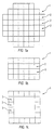
- Figs. 1a, 1b and 1c illustrate various excavating devices 1 which comprise a plurality of jet excavating units 2 which are arranged adjacent to one another, so that a desired cross section of a channel to be excavated in the soil is defined.
- the excavating device 1 shown in Fig. 1a is used to form a substantially circular cross section of the channel in the ground
- the excavating device 1 shown in Fig. 1b is used to form a substantially rectangular cross section of the channel.
- the jet excavating units 2 are in each case connected to two other jet excavating units 2, so that a rectangular cross section is enclosed.
- any other desired arrangements of jet excavating units are also possible, with corresponding cross sections of the channel to be excavated in the ground.
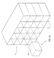
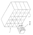
- the jet excavating units 2 comprise walls 20, and the jet excavating units 2 are pushed into compartments 8 of a support structure 7.
- the jet excavating units 2 are designed without walls.
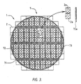
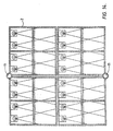
- Fig. 3 shows a rear view of an excavating device 1 according to the invention, in which a support structure 7 comprises three fixed principal bars 71, removable auxiliary bars 72 which are oriented transversely to the principal bars 71, and a support ring 73.
- the excavating device illustrated in Fig. 5 has been stopped by an obstacle 9, for example a rock-like material, so that the progress of the excavating device 1 in the ground has been blocked.
- an auxiliary bar 72a has been removed, after which two jet excavating units 2a are removed from the assembly of jet excavating units 2, so that the obstacle is accessible and can be removed easily.
- Figs. 4a and 4b show a first arrangement of jet devices 3 in a jet excavating unit 2.
- the jet excavating unit 2 may be designed both with and without walls; therefore, as in subsequent figures, the boundary of the jet excavating unit 2 is indicated by dashed lines.
- the jet devices 3 are fed with a jet liquid, such as water, from an inlet opening 12 of the jet excavating unit 2, so that jets 24 are formed.
- the jet devices 3 break up the soil to be excavated by spraying the jet liquid on to the soil at high pressure.
- the considerable turbulence which is generated while the soil is being broken up is to intimately mix the soil with the jet liquid, so that a mixture of soil and jet liquid is formed, which is easy to discharge.
- a front plate 91 and a back plate 92 serve as mechanical support if the excavation front becomes unstable and collapses.
- These plates 91, 92 also block large pieces of soil and other material which may become detached while the soil is being broken up, so that these pieces can be broken up more fully.
- a grate denoted by a dot-dashed line may be arranged between the bottom edge of the front plate 91 and the underside of the jet excavating unit 2, or between the top edge of the back plate 92 and the top side of the jet excavating unit 2, or between the front plate 91 and the back plate 92, in order to retain relatively large pieces of soil material.
- the plates 91, 92 divide the jet excavating unit at least into an excavation chamber (the space in which the jet devices 3 are arranged) and a mixing chamber 14.
- the mixing chamber 14 is provided with a supply of mixing liquid 15 and a liquid/soil outlet 13. In the case of sand, the particles have to be pushed over the edge of the back plate 92, into the mixing chamber 14.
- the jet devices 3 are too powerful, there will be an uncontrolled flow of sand into the mixing chamber 14 and the front will become unstable.
- clay the soil which enters the excavation chamber as a result of the advance of the excavating device 1 is broken up, the cohesion properties of clay, if appropriate in combination with a mixing chamber pressure, ensuring that the excavation front remains stable.
- the mixture of soil and jet liquid in the mixing chamber 14 is mixed with a mixing liquid, such as water, supplied via the mixing liquid feed 15 and is then discharged through the liquid-soil outlet 13.
- the jets 24 are directed in the same direction as the force of gravity and backwards, as seen in an excavation direction 25.
- Figs. 5a and 5b show a frontal arrangement of the jet devices 3, which are arranged on the front plate 91 and the back plate 92.
- Frontal jets 24 become more efficient as the soil penetrates further into the jet excavating unit 2, ensuring that the liquid/soil outlet 13 for the mixture of soil and jet liquid cannot become blocked and that the jet excavating unit 2 can always be blown empty.
- this arrangement of the jet devices 3 lacks a front boundary for the breaking up of the soil caused by the jet devices.
- an excessively strong jet liquid jet 24 may weaken the soil in front of the excavating device, making the excavation front unstable.
- Figs. 6a and 6b show a jet excavating unit 2 without plates and with jet devices 3 which spray jets 24 transversely with respect to the excavation direction 25 and in the same direction as the force of gravity.
- the breaking up of the soil caused by the jet devices will take place entirely within the jet excavating unit 2, so that a stable front can be ensured. It should be noted that soil which reaches behind the range of the jet devices 3 can no longer be removed from the jet excavating unit, which may cause blockage of the liquid/soil outlet 13.
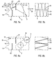
- Figs. 7a and 7b show an arrangement of the jet devices 3 which, as seen in the excavation direction 25, is directed obliquely backwards and counter to the force of gravity, which promotes the suspension of broken-up soil in the mixture of soil and jet liquid in the jet excavating unit 2.
- a non-return valve 27 which can pivot in the directions of double arrow 27a is hinged to the rear side of the front plate 91. The non-return valve 27 allows the mixture of soil and jet liquid to flow from the excavation chamber to the mixing chamber, but effectively prevents flow in the opposite direction.
- Figs. 8a and 8b show jet devices 3 arranged on the side walls of the jet excavating units 2, with the result that the soil in front of the back plate 92 is broken up successfully.
- Fig. 9 shows an excavating device 1 which comprises a number of substantially identical jet excavating units 2 as shown in Figs. 4a, 4b or Figs. 7a, 7b, which are connected, via connecting bars 10, to a support structure 7 (not shown in more detail).
- sensors 4 which measure the forces which the jet excavating units 2 are subject to during the advancement of the excavating device 1 in the base of the soil to be excavated, in the direction of arrow 25. In this case, it is ensured, in a manner not shown in more detail, for example by arranging the various jet excavating units moveably with respect to one another, that only the desired forces are measured.
- the sensors 4 are connected to control means 5 via control lines 51.
- control lines 52 run to a regulating unit 53 arranged in the jet excavating unit 2, such as for example an adjustable valve which sets the flow rate of the jet liquid flowing out of the jet devices 3.
- a regulating unit 53 arranged in the jet excavating unit 2, such as for example an adjustable valve which sets the flow rate of the jet liquid flowing out of the jet devices 3.
- the control arrangement is such that the flow rate of each of the jet devices 3 is set on the basis of the forces acting on the associated jet excavating unit 2, which are measured by the associated sensor 4. If one of the jet excavating units 2 is subject to resistance from the soil to be excavated which is above a predetermined level, which can be detected using the sensors 4, the flow rate of the jet devices 3 of the jet excavating unit 2 in question is increased.
- this jet excavating unit 2 will increase, with the result that more soil is excavated, after which the force which the soil to be excavated exerts on this jet excavating unit 2 decreases.
- the flow rate is then reduced by the regulating unit 53. In this way, the flow rate of the jet devices 3 of some or all of the jet excavating units 2 of the assembly of jet excavating units is adjusted continuously. This measurement and regulating process leads to excellent control of the excavation.
- the forces of a first jet excavating unit 2, which have been measured by the sensors 4, may be used to control the flow rate of jet devices 3 of a second jet excavating unit 2.
- one or more of the sensors 4 may also be connected to a plurality of jet excavating units 2 simultaneously, so that it is no longer the force on a single jet excavating unit 2, but rather the force on a plurality of jet excavating units 2, for example a horizontal row of such units, which is measured.
- This embodiment, which is not shown, is less finely tuned but reduces the number of sensors 4 required.
- the control unit 53 may be arranged outside the interior of the jet excavating unit 2.
- a control line 54 also runs to a drive device 6 which is connected, in a manner not shown in more detail, to the excavating device 1 for advancing the excavating device 1 in the excavation direction 25 on the basis of the forces acting on one or more of the jet excavating units 2, which have been measured by the sensors 4.
- the embodiment of the excavating device 1 illustrated in Fig. 10 comprises a support structure 7 which comprises compartments 8 which substantially completely surround the jet excavating units 2.
- the sensors 4 are arranged inside the support structure 7.
- This design of the support structure 7 allows various embodiments of the jet excavating units 2, two of which are illustrated in Figs. 2a and 2b.
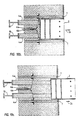
- Fig. 10a shows part of the support structure 7, in which the jet excavating unit 2 can move a short distance in the directions indicated by arrows 2b, 2c.
- the movement of the jet excavating unit 2 in the direction of the arrow 2b is limited by stops 10a.
- the jet excavating unit 2 is supported against the connecting bars 10 via sensors in the form of piston-cylinder units 4a.
- the pressures of fluids situated in the piston-cylinder units 4a are measured via lines 4b, which pressures represent a measure in particular of the force exerted on the jet excavating unit 2 in the direction of arrow 2b, provided that the jet excavating unit 2 is not bearing against one of the stops 10a.
- Figs. 10b and 10c essentially differs from that shown in Fig. 10a only in that the stroke of the piston-cylinder units 4a is selected to be considerably greater. Because of this, the piston-cylinder units 4a are not only able to function as sensors, but also can be used to displace the jet excavating unit 2 over a considerable distance. This can be seen by comparing Figs. 10b and 10c, the first of these figures showing the piston-cylinder units 4a at the beginning of their stroke, and the second of these figures showing the piston-cylinder units 4a at the end of their stroke. Thus, the jet excavating unit 2 can be moved forwards in the soil in the direction of arrow 2c independently of the support structure 7.
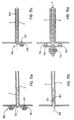
- Figs. 11a and 11b show views of another embodiment of the jet device 3 of a jet excavating unit 2.
- the jet device 3 comprises a spray head 66 and a tube piece 67 which is connected, via a closure means 16, to a feed line 68.
- the tube piece 67 is supported by attachment means 17 which are arranged on a top wall of the jet excavating unit 2.
- This embodiment of the jet device 3 allows simple installation and removal of the jet device 3, for example for maintenance purposes.
- the closure means 16 ensures that when the jet device 3 is removed, the pressure difference which prevails between the area in front of and behind a back wall 18 of the jet excavating unit 2 does not have to be evened out.
- Fig. 12 shows another embodiment of the jet devices 3 in the jet excavating unit 2.
- two series of jet devices 3 of the type described in Figs. 11a and 11b are positioned above one another.
- the jet devices 3 which are arranged substantially over half the height of the jet excavating unit are supported in attachment means 142 which are held by a transverse bar 114.
- This embodiment is beneficial in particular in the case of jet excavating units 2 which run extensively in the upward direction.
- jet excavating units 2 of this type the force of the jet liquid jets sprayed out of spray heads 66 arranged on a top wall 19 of the jet excavating unit 2 by the jet devices 3 is insufficient to break up the soil on the underside of the jet excavating unit 2, so that an additional jet device 3 is arranged closer to the underside of the jet excavating unit 2.
- jet devices 3 are possible, such as for example more than two jet devices 3 positioned above one another, jet devices 3 positioned next to one another in the excavation direction 25, jet devices 3 with jets 24 arranged at an angle to the excavation direction 25, jet devices 3 arranged on side walls of the jet excavating unit 2, jet devices 3 arranged on the top wall and the bottom wall, jet devices 3 with jets 24 which are oriented transversely to the excavation direction 25, jet devices 3 with jets 24 which are oriented parallel to the excavation direction, jet devices 3 arranged on a plate 91 or 92, jet devices 3 arranged on the back wall 18 of the jet excavating unit 2, or a combination of these options.
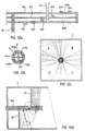
- Figs. 12a-12d show a jet liquid tube 146 which is divided into four passages 148a-148d by means of internally arranged partitions 147. Outlet openings 149 are arranged on the circumference of the tube 146, at a distance from one another in the longitudinal direction and at different angles in the circumferential direction. If it is ensured that each of the passages 148a-148d can be separately provided with jet liquid by means of a suitable valve control mechanism, jet liquid only flows out of the outlet openings 149 which correspond to the passage in question.
- Figs. 12b, 12c and 12d illustrate in particular the flow of jet liquid out of the outlet openings 149 corresponding to the passage 148a, into a sector A of a jet excavating unit 2.
- Other sectors B, C and D may be provided with jet liquid continuously or intermittently/in a pulsed supply, optionally simultaneously.
- a jet excavating unit may be provided intermittently or in a pulsed manner, optionally simultaneously, with jet liquid, it is also possible to actuate different jet excavating units, i.e. for these units to be actuated continuously or intermittently, successively or (possibly partially) simultaneously with other jet excavating units.
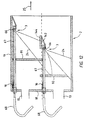
- Figs. 13a and 13b show the jet excavating unit 2 of an excavating device 1.
- a probe 11 determines the nature of the soil in front of the excavating device 1.
- the probe 11 can be used during excavation, since there are no bucket-wheel excavating devices or the like which could damage the probe 11.
- the probe 11 is supported by a frame 29, as indicated in Fig. 13b.
- the probe 11 can be arranged in the centre of the cross-sectional area of the jet excavating unit 2, but may also, for example, be arranged between jet excavating units 2, as shown in Fig. 14.
- Figs. 15a-15d show various embodiments of sealing means 150.
- a high pressure of groundwater and soil particles prevails in front of the jet excavating units 2.
- the atmospheric pressure of the inside of the channel formed in the ground prevails behind the jet excavating units 2.
- the jet excavating units 2 can in principle move independently of one another in the support structure 7, so that it is necessary to ensure a good seal for any space between the jet excavating units 2.
- the jet excavating units 2 have to be removable, so that obstacles can be removed and access can be gained to the excavation front ahead of the excavating device 1, and consequently the sealing means 150 also has to be made removable.
- This sealing means 150 can be produced in numerous different ways. Fig.
- a sealing means which comprises a deformable part 151, a rigid part 161 and a securing means 171.
- the deformable part 151 is secured over the space between the jet excavating units 2 by securing means 171, the rigid part 161 being enclosed above the deformable part and below the securing means 171.
- the securing means 171 is, for example, a screw or a bolt which can be removed from the back wall of the jet excavating unit, so that the sealing means 150 can easily be removed.
- the sealing means 150 which comprises a rigid part 162 which is arranged in the space between the side walls of two adjacent jet excavating units 2, and a deformable part 152 which is arranged on the rigid part 162 and connects the space between the rigid part 162 and the opposite side wall of an adjacent jet excavating unit 2.
- the sealing means 150 comprises a rigid part 163, a securing part 173 and a foam-like part 153.
- the rigid part 163 closes off the space between two adjacent jet excavating units 2 at the location of the back wall of the jet excavating units 2 and is secured to one of the jet excavating units 2 by the securing means 173.
- the sealing means 150 comprises deformable parts 154, angle brackets 164 and a securing means 174.
- angle brackets 164 are positioned on the wall of a compartment of the support structure 7 along which two adjacent jet excavating units 2 are arranged, both on one side and on the other side, a limb of the first angle bracket 164 being connected to the corresponding limb of the second angle bracket 164 by the securing means 174, so that the angle brackets 164 are rigidly connected to the wall of the support structure 7.
- the other limb of the angle bracket 164 is connected to the back wall of the jet excavating unit 2 via one of the deformable parts 154, so that the space between the adjacent jet excavating units 2 is sealed.
- Fig. 16 shows part of a back wall 180 of an excavating device, of which walls 182 between a jet excavating unit 184 and adjoining jet excavating units also form part.
- the jet excavating unit 184 has an excavation chamber 186 and a mixing chamber 188 which is common to various jet excavating units 184.
- In the back wall 180 there is a sealing passage 190 through which a jet liquid tube 192 can slide.
- the jet liquid tube 192 is provided with outlet openings 194, as has already been discussed in more detail above with reference to Figs. 12a-12d.
- a front plate 196 and a back plate 198 are attached to the jet liquid tube 192.
- the jet liquid tube 192 is supported on a force sensor 200 which is known per se, is not shown in detail and by means of which forces which are exerted on the plates 196 and 198 and are transmitted to the jet liquid tube 192 can be measured.
- the jet liquid tube 192 is also connected to a piston-cylinder unit 202, by means of which the jet liquid tube 192 can be displaced to the left from the position shown in Fig. 16 until the back plate 198 comes into contact with the passage 190, and vice versa.
- the piston-cylinder unit 202 can be used to measure the forces exerted on the plates 196 and 198 and transmitted to the jet liquid tube 192.
- the jet liquid tube 192 is provided with a diagrammatically illustrated controllable valve 204, the passage through which can be adjusted on the basis of the force measured by the force sensor 200 or the piston-cylinder unit 202.
- the force sensor 200 has a central jet liquid passage for the passage of jet liquid from the valve 204 to the jet liquid tube 192.
- Fig. 17 shows two jet excavating units 184 with a common mixing chamber 188.
- a pump 206 for discharging the mixture of jet liquid and soil which is situated in the mixing chamber 188 to a discharge line 208.
- Fig. 18 illustrates the way in which the jet liquid tube 192 and the plates 196, 198 connected thereto can be displaced in the direction of arrow 210 with the aid of the piston-cylinder unit 202 until the back plate 198 comes into contact with the passage 190.
- the valve 204 is closed.
- This option is advantageous in particular in order to allow an obstacle 212 situated in the excavation chamber 186 to enter the mixing chamber 188. If the dimensions of the obstacle are larger than the maximum dimensions of pieces which can be pumped through the pump 206, the obstacle 212 can be crushed in a crusher 214 and then discharged by the pump 206.
- the mixing chamber 188 could also be opened in the vicinity of its underside in order for the obstacle 212 to be removed.
- the mixing chamber is temporarily filled with a support liquid, such as bentonite, via a suitable feed opening (not shown in more detail), and is pressurized to such an extent that sufficient support is offered to the excavation front.
- a support liquid such as bentonite
- bentonite can be sprayed onto the exposed excavation front via the tube 192, and the mixing chamber 188 can be filled with pressurized air (for example if human intervention in the mixing chamber 188 should be desirable).
- Fig. 19 makes it clear that side of the jet excavating units which is to face towards the soil may be shaped in such a manner that an inclined or curved surface is formed on the front side of the excavating device, instead of a surface which is oriented transversely to the excavation direction as shown in Fig. 9.
- Fig. 19 shows a cross section through two channel walls 220, 222, with a number of jet excavating units 224 positioned in the channel wall 220.
- the jet excavating units 224 are accommodated in a support structure (not shown in more detail) and, as illustrated more clearly in Fig. 19a, each comprise a jet liquid tube 226, an excavation chamber 228, a mixing chamber 230, a front plate 232, a back plate 234, and a pump 236 for discharging a mixture of jet liquid and soil.
- Fig. 19 The option illustrated in Fig. 19 is advantageous, for example, when making transverse connections between previously dug tunnels.
- Components of the excavating device for forming the transverse connection may already be incorporated in the wall 220 of a tunnelling tube as a wall element when forming a tunnel, such as (components of) the support structure, front plates and back plates.
- the other components are arranged so as to make the excavating device operational.
- Fig. 20 shows a pump 240 with a delivery line 242 which is connected to a manifold 244. From the manifold 244, a plurality of, in this case four, lines 246, each provided with a controllable valve 248, run to jet liquid tubes 250 of jet excavating units 252. A system line 254, in which a controllable valve 255 is incorporated, also runs from the manifold 244 to a common mixing chamber 256 of the jet excavating units 252. A pump 258 discharges a mixture of jet liquid and soil which collects in the mixing chamber 256 via a line 260.
- the pump 240 supplies a constant flow rate which is adapted to the maximum amount of jet liquid required. This amount of liquid is distributed to the various jet excavating units 252 by the control means of the excavating device, with the aid of the valves 248, on the basis of the measured excavation force for each jet excavating unit 252. The remaining amount of jet liquid flows through the system line 254, via the valve 255, to the mixing chamber 256. In this way, the total amount of jet liquid supplied by the pump 240 to the excavating device is not influenced by the constantly changing jet liquid requirements of the individual jet excavating units 252, and the flow of jet liquid/soil mixture which the pump 258 has to discharge is constant.
- the valve 255 regulates the pressure, referred to here as the system pressure, upstream of the valves 248.
- This system pressure must always be at least a fraction higher than the maximum pressure required at a specific moment for the one or more jet excavating units.
- the delivery pressure of the pump 240 is no higher, or only slightly higher, than necessary, and the pressure drop across the valves 248 is minimized. As a result, the energy loss in the pump system also remains limited.
- the system pressure may also be divided into predetermined ranges, for example from 0-10 bar, from 10-30 bar, and from 30-50 bar. For example, if the maximum system pressure required at a specific moment is 17 bar, the valve 255 provides a system pressure of 30 bar, since 17 bar lies in the range from 10-30 bar.
- the excavating process can be controlled not only by measuring the forces which are exerted on the at least one jet excavating unit by the ground.
- the amount of soil collected by the one or more jet excavating units is calculated from the displacement of the jet excavating device in the excavation direction per unit time.
- the amount of soil which has been excavated by the one or more jet excavating units is determined by measuring the flow rate of the mixture which is discharged from the jet excavating unit or jet excavating units and measuring the density of this mixture.
- control means for controlling the excavation by the excavating device act on the basis of the determined soil balance, for example in order to set a flow rate of the jet liquid used in at least one of the jet devices. All of the other functions which were obtained above on the basis of a force measurement at one or more jet excavating units can also be obtained on the basis of monitoring the soil balance.
- To measure the density use is made of nuclear radiation, for which adequate protective measures are required.
- the invention is not restricted to the embodiments described above.
- one or more sensors 4 it is possible for one or more sensors 4 to be used not only for an assembly of jet excavating units 2, but also for a single jet excavating unit, in which case, although maintaining the soil balance is adequate to obtain a successfully controllable excavation process, it is less effective, simple and inexpensive than the option of using sensors to measure forces which the soil to be excavated exerts on the excavating device in order to control the excavation.
Landscapes
- Engineering & Computer Science (AREA)
- Mining & Mineral Resources (AREA)
- Geology (AREA)
- Life Sciences & Earth Sciences (AREA)
- General Life Sciences & Earth Sciences (AREA)
- Geochemistry & Mineralogy (AREA)
- Environmental & Geological Engineering (AREA)
- Physics & Mathematics (AREA)
- Fluid Mechanics (AREA)
- Mechanical Engineering (AREA)
- Consolidation Of Soil By Introduction Of Solidifying Substances Into Soil (AREA)
- Earth Drilling (AREA)
- Ultra Sonic Daignosis Equipment (AREA)
- Steroid Compounds (AREA)
- Finger-Pressure Massage (AREA)
- Centrifugal Separators (AREA)
- Preparing Plates And Mask In Photomechanical Process (AREA)
- Formation And Processing Of Food Products (AREA)
Abstract
Description
Claims (46)
- Excavating device for forming a channel of predetermined cross section in the ground, in an excavation direction, comprising
an assembly of jet excavating units (2), which together define the cross section of the channel and are each provided with at least one jet device (3) which can be operated with jet liquid, characterised in thatat least one sensor (4) connected to at least one of the jet excavating units, for measuring a force which is exerted on the at least one jet excavating unit (2) by the ground substantially parallel to the excavation direction;control means (5) for controlling the excavation by the excavating device on the basis of the force measured by the at least one sensor. - Excavating device according to claim 1, characterized in that the control means are adapted to set a flow rate of the jet liquid used in at least one of the jet devices.
- Excavating device according to claim 2, characterized in that the control means are adapted to set the flow rate of the jet liquid of the at least one jet device of the jet excavating unit which is connected to the at least one sensor.
- Excavating device according to claim 2 or 3, characterized in that the control means are adapted to increase or reduce the flow rate of the jet liquid of the at least one jet device in the event of an increase or decrease in the force measured by the at least one sensor.
- Excavating device according to any of claims 2-4, characterized in that the setting of the flow rate of the jet liquid of the at least one jet device can be varied between a predetermined minimum level and a predetermined maximum level.
- Excavating device according to any of the preceding claims, characterized in that the control means are adapted to vary the flow rate of the jet liquid of the at least one jet device of at least one jet excavating unit between a predetermined minimum and a predetermined maximum level on the basis of the force measured by the at least one sensor connected to the at least one jet excavating unit.
- Excavating device according to any of the preceding claims, characterized in that the control means are adapted to feed jet liquid to the at least one jet device of at least one of the jet excavating units where the force exceeds a defined level, and to limit the feed of jet liquid to a minimum value when the force has fallen below the said level.
- Excavating device according to any of the preceding claims, characterized in that the jet devices are each fed, via a line in which a controllable valve is incorporated, from a jet pump which supplies a constant flow rate of jet liquid, that fraction of the jet liquid flow which is not taken up by the jet devices being supplied, via at least one system line in which a controllable valve is incorporated, to a space of the jet excavating units.
- Excavating device according to claim 8, characterized in that the control means are adapted to set the controllable valve in the at least one system line in such a manner that a delivery pressure set for the jet pump is marginally higher than the maximum pressure required for the jet devices.
- Excavating device according to any of the preceding claims and also comprising a drive device for displacing the excavating device substantially in the excavation direction, characterized in that the control means are adapted to control the drive device.
- Excavating device according to claim 10, characterized in that the control means are adapted to measure the current amount of jet liquid required for the assembly of jet excavating units and to adapt the velocity of the drive device to the available flow of jet liquid for the assembly of jet excavating units.
- Excavating device according to any of the preceding claims, characterized by a support structure which supports the jet excavating units.
- Excavating device according to claim 12, characterized in that part of the support structure can be removed for the purpose of removing at least one of the jet excavating units.
- Excavating device according to any of claims 12 or 13, characterized in that the support structure is provided with compartments which substantially completely surround the jet excavating units.
- Excavating device according to claim 12, characterized in that one or more of the jet excavating units can be displaced with respect to the support structure, substantially parallel to the excavation direction, with the aid of a displacement device.
- Excavating device according to claim 15, characterized in that the displacement device comprises at least one jack.
- Excavating device according to any of the preceding claims, characterized in that the at least one jet device of at least one jet excavating unit is adapted to expel a jet of jet liquid in a fixed direction.
- Excavating device according to any of the preceding claims, characterized in that the at least one jet device of the at least one jet excavating unit is adapted to be operated intermittently.
- Excavating device according to claim 17, characterized in that the jet liquid jet which is expelled in a fixed direction from the at least one jet device of the at least one jet excavating unit is oriented at an angle to the excavation direction.
- Excavating device according to claim 19, characterized in that the jet liquid jet which is expelled in a fixed direction from the at least one jet device of the at least one jet excavating unit is inclined backwards, as seen in the excavation direction.
- Excavating device according to any of the preceding claims, characterized in that the at least one jet device comprises at least one tube which extends substantially in the excavation direction and is provided on its circumference with at least one outlet opening.
- Excavating device according to claim 21, characterized in that the tube is arranged centrally in the jet excavating unit and comprises a number of outlet openings.
- Excavating device according to claim 22, characterized in that the outlet openings are positioned at a distance from one another, as seen in the longitudinal direction of the tube.
- Excavating device according to claim 22 or 23, characterized in that the outlet openings are positioned at different angles, as seen in the circumferential direction of the tube.
- Excavating device according to claim 17, characterized in that at least one of the jet excavating units comprises a number of jet devices, the jet liquid jets from which are oriented in different, fixed directions.
- Excavating device according to claim 25, characterized in that the jet devices are operated intermittently.
- Excavating device according to claim 26, characterized in that the jet devices are operated alternately.
- Excavating device according to claim 25, characterized in that at least one of the jet devices is arranged on a side wall of the at least one jet excavating unit, and in that the jet liquid jet which is expelled in a fixed direction from the at least one jet device is oriented substantially transversely to the excavation direction.
- Excavating device according to any of the preceding claims, characterized in that at least one jet excavating unit is provided with means in which the at least one jet device thereof is releasably secured.
- Excavating device according to claim 29, characterized in that the jet device is arranged in the jet excavating unit through a passage in a rear wall of the jet excavating unit.
- Excavating device according to claim 30, characterized in that the passage comprises a closure means.
- Excavating device according to any of the preceding claims, characterized by at least one probe which is adapted to determine the nature of the soil at a distance in front of the jet excavating unit, as seen in the excavation direction, during excavation.
- Excavating device according to any of the preceding claims, characterized by at least two probes for determining the nature of the soil between and around the at least two probes.
- Excavating device according to any of the preceding claims, characterized in that there is at least one removable sealing means for sealing space between adjoining jet excavating units.
- Excavating device according to any of claims 12-34, characterized in that there is at least one removable sealing means for sealing space between a jet excavating unit and the support structure.
- Excavating device according to any of claims 12-35, characterized in that the at least one sensor connected to the at least one jet excavating unit is positioned between the support structure and the at least one jet excavating unit.
- Excavating device according to any of the preceding claims, characterized in that the at least one sensor comprises a piston-cylinder unit which can be operated by a fluid, which sensor is provided with pressure measuring means for recording a pressure of the fluid.
- Excavating device according to any of the preceding claims, characterized in that the at least one jet excavating unit comprises at least one plate which is arranged substantially transversely to the excavation direction, and in that the at least one sensor connected to the at least one jet excavating unit is adapted to measure substantially the force acting on the plate in the excavation direction.
- Excavating device according to claim 38, characterized in that the at least one sensor is connected to the at least one plate via the jet device.
- Excavating device according to any of the preceding claims, characterized in that an excavation chamber is formed in a jet excavating unit by a space in which the at least one jet device is arranged, the excavation chamber being adjoined, on the rear side, as seen counter to the excavation direction, by, in succession, a front plate, which extends from the top side of the excavation chamber to a distance from the underside of the excavation chamber, and a back plate, which extends at a distance from the front plate, from the underside of the excavation chamber to a distance from the top side of the excavation chamber.
- Excavating device according to claim 40, characterized in that a mixing chamber is formed behind the back plate, by a space with an outlet opening for discharging a mixture of soil and jet liquid.
- Excavating device according to claim 41, characterized in that the mixing chamber comprises a space which is common to a number of jet excavating units.
- Excavating device according to claim 41 or 42, characterized in that the outlet opening is situated in the vicinity of an underside of the mixing chamber.
- Excavating device according to any of claims 41-43, characterized in that a crusher is arranged in the mixing chamber, upstream of the outlet opening.
- Excavating device according to any of claims 41-44, characterized in that a non-return valve is arranged between the excavation chamber and the mixing chamber, in order to allow the mixture of soil and jet liquid to pass from the excavation chamber to the mixing chamber but blocking it from passing in the opposite direction.
- Excavating device according to claim 40, characterized in that the front plate or the back plate is connected to a grate which extends from the underside or the top side of the excavation chamber to the front plate or the back plate, respectively, in such a manner that material which is retained by the grate returns, under the force of gravity, into an area of the jet excavating unit which is directly reached by the liquid jet from the at least one jet device.
Applications Claiming Priority (7)
| Application Number | Priority Date | Filing Date | Title |
|---|---|---|---|
| NL1012505 | 1999-07-02 | ||
| NL1012505A NL1012505C2 (en) | 1999-07-02 | 1999-07-02 | Excavating device for forming channel in ground has assembly of jet excavating units defining cross section of channel, with sensor connected to at least one unit for measuring force exerted by ground |
| NL1013687 | 1999-11-28 | ||
| NL1013687A NL1013687C1 (en) | 1999-07-02 | 1999-11-28 | Excavating device for forming channel in ground has assembly of jet excavating units defining cross section of channel, with sensor connected to at least one unit for measuring force exerted by ground |
| NL1015365A NL1015365C1 (en) | 1999-07-02 | 2000-05-31 | Jet excavator. |
| NL1015365 | 2000-05-31 | ||
| PCT/NL2000/000459 WO2001002692A1 (en) | 1999-07-02 | 2000-06-30 | Jet excavating device |
Publications (2)
| Publication Number | Publication Date |
|---|---|
| EP1109988A1 EP1109988A1 (en) | 2001-06-27 |
| EP1109988B1 true EP1109988B1 (en) | 2004-02-25 |
Family
ID=27351213
Family Applications (1)
| Application Number | Title | Priority Date | Filing Date |
|---|---|---|---|
| EP00946519A Expired - Lifetime EP1109988B1 (en) | 1999-07-02 | 2000-06-30 | Jet excavating device |
Country Status (9)
| Country | Link |
|---|---|
| US (1) | US6385868B2 (en) |
| EP (1) | EP1109988B1 (en) |
| JP (1) | JP2003503618A (en) |
| AT (1) | ATE260402T1 (en) |
| DE (1) | DE60008488T2 (en) |
| DK (1) | DK1109988T3 (en) |
| ES (1) | ES2214290T3 (en) |
| NL (1) | NL1015365C1 (en) |
| WO (1) | WO2001002692A1 (en) |
Cited By (1)
| Publication number | Priority date | Publication date | Assignee | Title |
|---|---|---|---|---|
| NL1026229C2 (en) | 2004-05-19 | 2005-11-22 | Heerema Marine Contractors B V | Method for forming a channel in the ground, excavating device for forming a channel in the ground, assembly of an excavating device and a construction element. |
Families Citing this family (1)
| Publication number | Priority date | Publication date | Assignee | Title |
|---|---|---|---|---|
| CN117780426B (en) * | 2024-01-17 | 2024-09-24 | 河南理工大学 | Device and method for coal seam gas extraction and permeability enhancement |
Family Cites Families (25)
| Publication number | Priority date | Publication date | Assignee | Title |
|---|---|---|---|---|
| US2208608A (en) * | 1939-02-13 | 1940-07-23 | Alfred F Stanley | Apparatus for tunneling |
| USRE28945E (en) * | 1972-08-24 | 1976-08-31 | Marcona Corporation | Method and apparatus for excavating settled body of solids |
| GB1446464A (en) * | 1973-11-08 | 1976-08-18 | Humphreys Corp | Cutting rock material |
| US4095435A (en) * | 1975-04-08 | 1978-06-20 | Koichi Uemura | Method of advancing a plurality of longitudinally arranged movable constructional units forwardly successively in a self-running manner and apparatus for performing same |
| FR2354444A1 (en) * | 1976-06-11 | 1978-01-06 | Gaillard Rene | Tunnel driving machine structure - has head consisting of tubular components movable in relation to each other by rams |
| US4401345A (en) * | 1980-04-30 | 1983-08-30 | Flow Industries, Inc. | Hydraulic borehole mining system |
| US4863101A (en) * | 1982-12-06 | 1989-09-05 | Acb Technology Corporation | Accelerating slugs of liquid |
| US4534427A (en) * | 1983-07-25 | 1985-08-13 | Wang Fun Den | Abrasive containing fluid jet drilling apparatus and process |
| US4854770A (en) * | 1984-04-16 | 1989-08-08 | Indescor Hydrodynamics Inc. | Method and apparatus for removal of surface material |
| US4708395A (en) * | 1984-11-05 | 1987-11-24 | Conoco Inc. | Remotely sensing of excavation cavity during mining |
| US4610321A (en) * | 1985-03-25 | 1986-09-09 | Whaling Michael H | Cavitating jet device |
| JPS6255316A (en) * | 1985-09-04 | 1987-03-11 | Yuji Kaneko | Method and apparatus for forming continuous horizontal columnar wall |
| US4739841A (en) * | 1986-08-15 | 1988-04-26 | Anadrill Incorporated | Methods and apparatus for controlled directional drilling of boreholes |
| JP2619689B2 (en) * | 1988-06-03 | 1997-06-11 | 五洋建設株式会社 | Shield excavator |
| US4930586A (en) * | 1989-05-12 | 1990-06-05 | Ben Wade Oakes Dickinson, III | Hydraulic drilling apparatus and method |
| AT396505B (en) * | 1990-06-11 | 1993-10-25 | Geodrill Bohr Gmbh | METHOD AND DEVICE FOR THE UNDERGROUND PRODUCTION OF CHANNELS, TUBES OR THE LIKE. |
| JPH0460091A (en) * | 1990-06-28 | 1992-02-26 | Yoshida Tekkosho:Kk | Nonlinear type boring device |
| ATE140512T1 (en) * | 1991-04-05 | 1996-08-15 | Toda Corp | METHOD FOR PRODUCING AN ELONGATED UNDERGROUND SPACE OF SQUARE OR RECTANGULAR CROSS SECTION |
| US5771984A (en) * | 1995-05-19 | 1998-06-30 | Massachusetts Institute Of Technology | Continuous drilling of vertical boreholes by thermal processes: including rock spallation and fusion |
| GB9517378D0 (en) * | 1995-08-24 | 1995-10-25 | Sofitech Nv | Hydraulic jetting system |
| US6243625B1 (en) * | 1996-04-12 | 2001-06-05 | N E D Corp. | Automated quarry operation with communication interface |
| US5879057A (en) * | 1996-11-12 | 1999-03-09 | Amvest Corporation | Horizontal remote mining system, and method |
| EP0890707A1 (en) * | 1997-07-11 | 1999-01-13 | Heerema Ondergrondse Infrastructuren B.V. | Method, system and device for building a wall in the ground |
| IT243298Y1 (en) * | 1997-07-11 | 2002-03-04 | Mait Spa | MULTIPLE-HEAD DRILLING GROUP FOR LOOSE GROUND DRILLING MACHINES |
| US6289998B1 (en) * | 1998-01-08 | 2001-09-18 | Baker Hughes Incorporated | Downhole tool including pressure intensifier for drilling wellbores |
-
2000
- 2000-05-31 NL NL1015365A patent/NL1015365C1/en not_active IP Right Cessation
- 2000-06-30 ES ES00946519T patent/ES2214290T3/en not_active Expired - Lifetime
- 2000-06-30 AT AT00946519T patent/ATE260402T1/en not_active IP Right Cessation
- 2000-06-30 DK DK00946519T patent/DK1109988T3/en active
- 2000-06-30 WO PCT/NL2000/000459 patent/WO2001002692A1/en not_active Ceased
- 2000-06-30 EP EP00946519A patent/EP1109988B1/en not_active Expired - Lifetime
- 2000-06-30 DE DE60008488T patent/DE60008488T2/en not_active Expired - Fee Related
- 2000-06-30 JP JP2001507904A patent/JP2003503618A/en active Pending
-
2001
- 2001-03-02 US US09/796,608 patent/US6385868B2/en not_active Expired - Fee Related
Cited By (1)
| Publication number | Priority date | Publication date | Assignee | Title |
|---|---|---|---|---|
| NL1026229C2 (en) | 2004-05-19 | 2005-11-22 | Heerema Marine Contractors B V | Method for forming a channel in the ground, excavating device for forming a channel in the ground, assembly of an excavating device and a construction element. |
Also Published As
| Publication number | Publication date |
|---|---|
| ATE260402T1 (en) | 2004-03-15 |
| US20010035674A1 (en) | 2001-11-01 |
| NL1015365C1 (en) | 2001-01-03 |
| JP2003503618A (en) | 2003-01-28 |
| DE60008488D1 (en) | 2004-04-01 |
| EP1109988A1 (en) | 2001-06-27 |
| ES2214290T3 (en) | 2004-09-16 |
| DK1109988T3 (en) | 2004-06-28 |
| WO2001002692A1 (en) | 2001-01-11 |
| US6385868B2 (en) | 2002-05-14 |
| DE60008488T2 (en) | 2004-12-02 |
Similar Documents
| Publication | Publication Date | Title |
|---|---|---|
| USRE34620E (en) | Trenching apparatus and methods of forming inground retaining walls | |
| CN101501277B (en) | Adjustable weir for hydroelectric dam installations | |
| EP0889200B1 (en) | Tunnel excavation method and tunnel excavator | |
| US4896445A (en) | Method for reducing costs and environmental impact of dredging | |
| KR20110079703A (en) | Drag head for self-driving hopper dredger and dredging method for dredging using this drag head | |
| US3799614A (en) | Method and apparatus for excavating settled body of solids | |
| US6385868B2 (en) | Jet excavating device | |
| USRE28945E (en) | Method and apparatus for excavating settled body of solids | |
| US4991997A (en) | Method and apparatus for the transport of particulate solids using a submerged fluid induction device | |
| US5443305A (en) | Tunnelling machine | |
| NL1013687C1 (en) | Excavating device for forming channel in ground has assembly of jet excavating units defining cross section of channel, with sensor connected to at least one unit for measuring force exerted by ground | |
| CN117846628A (en) | Shield tunneling machine with cutter head capable of preventing mud cake from being formed | |
| JPH07173991A (en) | Pressure adjusting device for horizontal pit excavating device and pressure adjusting method therefor | |
| EP0842330B1 (en) | Method and device for burying a conduit under water | |
| KR0174725B1 (en) | Process for building a concrete structure in loose matter, from ground level and equipment for carrying out said process | |
| US3617094A (en) | Method and apparatus for handling material | |
| JP4702821B2 (en) | Solidification pile construction device and construction method | |
| NL1016952C2 (en) | Excavating device for forming channel in ground has assembly of jet excavating units defining cross section of channel, with sensor connected to at least one unit for measuring force exerted by ground | |
| ZA200510400B (en) | Method and device for extracting extraction products in underground mining | |
| NL1016917C2 (en) | Excavating device for forming channel in ground has assembly of jet excavating units defining cross section of channel, with sensor connected to at least one unit for measuring force exerted by ground | |
| JP4280889B2 (en) | Excavation soil hydraulic transportation equipment in earth pressure shield method | |
| CN222894256U (en) | Flushing system for tunnel boring machine and cutting type caisson tunnel boring machine | |
| JPH076238Y2 (en) | Tunnel excavator | |
| JP3622903B2 (en) | Soft ground improvement method and its equipment | |
| JPH06264676A (en) | Underwater drilling equipment and underwater drilling method |
Legal Events
| Date | Code | Title | Description |
|---|---|---|---|
| PUAI | Public reference made under article 153(3) epc to a published international application that has entered the european phase |
Free format text: ORIGINAL CODE: 0009012 |
|
| 17P | Request for examination filed |
Effective date: 20010220 |
|
| AK | Designated contracting states |
Kind code of ref document: A1 Designated state(s): AT BE CH CY DE DK ES FI FR GB GR IE IT LI LU MC NL PT SE |
|
| GRAP | Despatch of communication of intention to grant a patent |
Free format text: ORIGINAL CODE: EPIDOSNIGR1 |
|
| GRAS | Grant fee paid |
Free format text: ORIGINAL CODE: EPIDOSNIGR3 |
|
| GRAA | (expected) grant |
Free format text: ORIGINAL CODE: 0009210 |
|
| AK | Designated contracting states |
Kind code of ref document: B1 Designated state(s): AT BE CH CY DE DK ES FI FR GB GR IE IT LI LU MC NL PT SE |
|
| PG25 | Lapsed in a contracting state [announced via postgrant information from national office to epo] |
Ref country code: LI Free format text: LAPSE BECAUSE OF FAILURE TO SUBMIT A TRANSLATION OF THE DESCRIPTION OR TO PAY THE FEE WITHIN THE PRESCRIBED TIME-LIMIT Effective date: 20040225 Ref country code: CY Free format text: LAPSE BECAUSE OF FAILURE TO SUBMIT A TRANSLATION OF THE DESCRIPTION OR TO PAY THE FEE WITHIN THE PRESCRIBED TIME-LIMIT Effective date: 20040225 Ref country code: AT Free format text: LAPSE BECAUSE OF FAILURE TO SUBMIT A TRANSLATION OF THE DESCRIPTION OR TO PAY THE FEE WITHIN THE PRESCRIBED TIME-LIMIT Effective date: 20040225 Ref country code: FI Free format text: LAPSE BECAUSE OF FAILURE TO SUBMIT A TRANSLATION OF THE DESCRIPTION OR TO PAY THE FEE WITHIN THE PRESCRIBED TIME-LIMIT Effective date: 20040225 Ref country code: CH Free format text: LAPSE BECAUSE OF FAILURE TO SUBMIT A TRANSLATION OF THE DESCRIPTION OR TO PAY THE FEE WITHIN THE PRESCRIBED TIME-LIMIT Effective date: 20040225 |
|
| REG | Reference to a national code |
Ref country code: GB Ref legal event code: FG4D |
|
| REG | Reference to a national code |
Ref country code: CH Ref legal event code: EP |
|
| REG | Reference to a national code |
Ref country code: IE Ref legal event code: FG4D |
|
| REF | Corresponds to: |
Ref document number: 60008488 Country of ref document: DE Date of ref document: 20040401 Kind code of ref document: P |
|
| PG25 | Lapsed in a contracting state [announced via postgrant information from national office to epo] |
Ref country code: SE Free format text: LAPSE BECAUSE OF FAILURE TO SUBMIT A TRANSLATION OF THE DESCRIPTION OR TO PAY THE FEE WITHIN THE PRESCRIBED TIME-LIMIT Effective date: 20040525 Ref country code: GR Free format text: LAPSE BECAUSE OF FAILURE TO SUBMIT A TRANSLATION OF THE DESCRIPTION OR TO PAY THE FEE WITHIN THE PRESCRIBED TIME-LIMIT Effective date: 20040525 |
|
| REG | Reference to a national code |
Ref country code: DK Ref legal event code: T3 |
|
| PG25 | Lapsed in a contracting state [announced via postgrant information from national office to epo] |
Ref country code: MC Free format text: LAPSE BECAUSE OF NON-PAYMENT OF DUE FEES Effective date: 20040630 Ref country code: LU Free format text: LAPSE BECAUSE OF NON-PAYMENT OF DUE FEES Effective date: 20040630 |
|
| ET | Fr: translation filed | ||
| REG | Reference to a national code |
Ref country code: CH Ref legal event code: PL |
|
| REG | Reference to a national code |
Ref country code: ES Ref legal event code: FG2A Ref document number: 2214290 Country of ref document: ES Kind code of ref document: T3 |
|
| PLBE | No opposition filed within time limit |
Free format text: ORIGINAL CODE: 0009261 |
|
| STAA | Information on the status of an ep patent application or granted ep patent |
Free format text: STATUS: NO OPPOSITION FILED WITHIN TIME LIMIT |
|
| 26N | No opposition filed |
Effective date: 20041126 |
|
| PG25 | Lapsed in a contracting state [announced via postgrant information from national office to epo] |
Ref country code: PT Free format text: LAPSE BECAUSE OF NON-PAYMENT OF DUE FEES Effective date: 20040725 |
|
| PGFP | Annual fee paid to national office [announced via postgrant information from national office to epo] |
Ref country code: DK Payment date: 20080626 Year of fee payment: 9 |
|
| PGFP | Annual fee paid to national office [announced via postgrant information from national office to epo] |
Ref country code: BE Payment date: 20080626 Year of fee payment: 9 Ref country code: IT Payment date: 20080626 Year of fee payment: 9 |
|
| PGFP | Annual fee paid to national office [announced via postgrant information from national office to epo] |
Ref country code: DE Payment date: 20080625 Year of fee payment: 9 Ref country code: ES Payment date: 20080626 Year of fee payment: 9 Ref country code: IE Payment date: 20080526 Year of fee payment: 9 Ref country code: NL Payment date: 20080626 Year of fee payment: 9 |
|
| PGFP | Annual fee paid to national office [announced via postgrant information from national office to epo] |
Ref country code: FR Payment date: 20080626 Year of fee payment: 9 |
|
| PGFP | Annual fee paid to national office [announced via postgrant information from national office to epo] |
Ref country code: GB Payment date: 20080529 Year of fee payment: 9 |
|
| BERE | Be: lapsed |
Owner name: *HEEREMA HOLDING CONSTRUCTION INC. Effective date: 20090630 |
|
| REG | Reference to a national code |
Ref country code: DK Ref legal event code: EBP |
|
| GBPC | Gb: european patent ceased through non-payment of renewal fee |
Effective date: 20090630 |
|
| NLV4 | Nl: lapsed or anulled due to non-payment of the annual fee |
Effective date: 20100101 |
|
| REG | Reference to a national code |
Ref country code: FR Ref legal event code: ST Effective date: 20100226 |
|
| REG | Reference to a national code |
Ref country code: IE Ref legal event code: MM4A |
|
| PG25 | Lapsed in a contracting state [announced via postgrant information from national office to epo] |
Ref country code: IE Free format text: LAPSE BECAUSE OF NON-PAYMENT OF DUE FEES Effective date: 20090630 Ref country code: FR Free format text: LAPSE BECAUSE OF NON-PAYMENT OF DUE FEES Effective date: 20090630 |
|
| PG25 | Lapsed in a contracting state [announced via postgrant information from national office to epo] |
Ref country code: GB Free format text: LAPSE BECAUSE OF NON-PAYMENT OF DUE FEES Effective date: 20090630 |
|
| PG25 | Lapsed in a contracting state [announced via postgrant information from national office to epo] |
Ref country code: BE Free format text: LAPSE BECAUSE OF NON-PAYMENT OF DUE FEES Effective date: 20090630 Ref country code: DE Free format text: LAPSE BECAUSE OF NON-PAYMENT OF DUE FEES Effective date: 20100101 |
|
| PG25 | Lapsed in a contracting state [announced via postgrant information from national office to epo] |
Ref country code: NL Free format text: LAPSE BECAUSE OF NON-PAYMENT OF DUE FEES Effective date: 20100101 Ref country code: DK Free format text: LAPSE BECAUSE OF NON-PAYMENT OF DUE FEES Effective date: 20090630 |
|
| REG | Reference to a national code |
Ref country code: ES Ref legal event code: FD2A Effective date: 20090701 |
|
| PG25 | Lapsed in a contracting state [announced via postgrant information from national office to epo] |
Ref country code: ES Free format text: LAPSE BECAUSE OF NON-PAYMENT OF DUE FEES Effective date: 20090701 |
|
| PG25 | Lapsed in a contracting state [announced via postgrant information from national office to epo] |
Ref country code: IT Free format text: LAPSE BECAUSE OF NON-PAYMENT OF DUE FEES Effective date: 20090630 |