EP1109639B1 - Positioning apparatus and method for precision pouring of a liquid from a vessel - Google Patents
Positioning apparatus and method for precision pouring of a liquid from a vessel Download PDFInfo
- Publication number
- EP1109639B1 EP1109639B1 EP00944645A EP00944645A EP1109639B1 EP 1109639 B1 EP1109639 B1 EP 1109639B1 EP 00944645 A EP00944645 A EP 00944645A EP 00944645 A EP00944645 A EP 00944645A EP 1109639 B1 EP1109639 B1 EP 1109639B1
- Authority
- EP
- European Patent Office
- Prior art keywords
- rotation
- axis
- vessel
- supporting structure
- output
- Prior art date
- Legal status (The legal status is an assumption and is not a legal conclusion. Google has not performed a legal analysis and makes no representation as to the accuracy of the status listed.)
- Expired - Lifetime
Links
- 239000007788 liquid Substances 0.000 title claims description 25
- 238000000034 method Methods 0.000 title claims description 22
- 239000012530 fluid Substances 0.000 claims description 15
- 230000000712 assembly Effects 0.000 claims description 3
- 238000000429 assembly Methods 0.000 claims description 3
- 230000033001 locomotion Effects 0.000 description 36
- 238000013519 translation Methods 0.000 description 12
- 238000013459 approach Methods 0.000 description 5
- 230000008859 change Effects 0.000 description 5
- 238000012423 maintenance Methods 0.000 description 4
- 229910052751 metal Inorganic materials 0.000 description 4
- 239000002184 metal Substances 0.000 description 4
- 230000002093 peripheral effect Effects 0.000 description 4
- 230000008569 process Effects 0.000 description 4
- 238000006073 displacement reaction Methods 0.000 description 3
- 238000007789 sealing Methods 0.000 description 3
- 230000004913 activation Effects 0.000 description 2
- 238000004364 calculation method Methods 0.000 description 2
- 238000011109 contamination Methods 0.000 description 2
- 239000000498 cooling water Substances 0.000 description 2
- 230000009977 dual effect Effects 0.000 description 2
- 239000003517 fume Substances 0.000 description 2
- 239000004519 grease Substances 0.000 description 2
- 238000005461 lubrication Methods 0.000 description 2
- 230000007246 mechanism Effects 0.000 description 2
- 238000012545 processing Methods 0.000 description 2
- 230000008439 repair process Effects 0.000 description 2
- 230000003213 activating effect Effects 0.000 description 1
- 229910045601 alloy Inorganic materials 0.000 description 1
- 239000000956 alloy Substances 0.000 description 1
- 238000004458 analytical method Methods 0.000 description 1
- 230000002457 bidirectional effect Effects 0.000 description 1
- 238000009833 condensation Methods 0.000 description 1
- 230000005494 condensation Effects 0.000 description 1
- 238000004320 controlled atmosphere Methods 0.000 description 1
- 230000000881 depressing effect Effects 0.000 description 1
- 238000010586 diagram Methods 0.000 description 1
- 238000005516 engineering process Methods 0.000 description 1
- 230000007613 environmental effect Effects 0.000 description 1
- 239000007789 gas Substances 0.000 description 1
- 238000009434 installation Methods 0.000 description 1
- 239000011344 liquid material Substances 0.000 description 1
- 238000002844 melting Methods 0.000 description 1
- 230000008018 melting Effects 0.000 description 1
- 238000005272 metallurgy Methods 0.000 description 1
- 150000002739 metals Chemical class 0.000 description 1
- 239000012768 molten material Substances 0.000 description 1
- 238000012856 packing Methods 0.000 description 1
- 230000003068 static effect Effects 0.000 description 1
- 238000003860 storage Methods 0.000 description 1
- 239000003039 volatile agent Substances 0.000 description 1
Images


Classifications
-
- B—PERFORMING OPERATIONS; TRANSPORTING
- B22—CASTING; POWDER METALLURGY
- B22D—CASTING OF METALS; CASTING OF OTHER SUBSTANCES BY THE SAME PROCESSES OR DEVICES
- B22D37/00—Controlling or regulating the pouring of molten metal from a casting melt-holding vessel
Definitions
- the present invention relates to precision pouring of a liquid from a vessel into a container, particularly when the vessel and container are located inside a chamber.
- liquids such as molten metals and alloys
- processing includes the pouring of a liquid at a pre-determined rate from a vessel, such as a melting furnace, into a container such as a mold.
- a vessel generally having a pour lip and containing a liquid is tilted to establish a pour stream that is targeted at an opening in the container.
- the desired pour rate may be fixed, or it may be profiled, meaning that the desired rate varies during the course of the pour.
- the relative positions of the vessel and container must be controllable to allow the pre-determined flow rate and aim point to be maintained.
- the horizontal (or X-axis) position of the vessel and its tilt angle measured from the Y-axis must be adjustable. If it is also desired to simultaneously control the vertical distance of the pour lip above the target opening, the vertical position of the vessel must also be controlled.
- a known approach to meeting the above requirements is to mount the vessel on a manipulator, located inside the chamber.
- a manipulator is difficult to access for maintenance or repair.
- any mechanism so located is likely to be exposed to liquid splash, fume, condensation of volatiles evolved from the liquid, etc., so it is likely to need frequent maintenance or repair. Therefore, it is advantageous that essentially all of the mechanism for moving and tilting the vessel be accessibly located outside of the chamber and sealed such that it is not exposed to the atmosphere inside.
- the seal system must also maintain the integrity of the atmosphere, allowing gases to leak neither out of nor into the chamber.
- a prior art approach that achieves some of the above objectives is to mount the vessel eccentrically on a plate which is supported from the chamber wall and which rotates about the center of a circular peripheral seal.
- Rotary motion about said center is advantageous because sealing surfaces that were covered by the seal, and therefore protected from contamination prior to such rotation, remain covered and protected during and after rotation.
- Such protection from contamination such as splash, fume and condensates improves seal life.
- Rotation about this first axis which is at a relatively large vertical distance below the vessel pour lip, will move the pour lip primarily in the horizontal direction, as long as the amount of angular motion is kept small.
- Rotation about a second axis located closer to the vessel's pour lip than the first axis, tilts the vessel to assist the pouring of molten metal from the vessel.
- This approach has its own disadvantages.
- the requirement that the amount of angular motion about the first axis be kept small, means that for a given amount of traverse motion, a relatively large distance must be maintained between the pour lip and the first axis of rotation.
- This requirement makes the rotary plate relatively large in diameter. Consequently, relatively large forces are exerted on it when there is a significant differential pressure between the outside and the inside of the chamber. In such a case, which happens commonly, the plate must be built to withstand these large forces. This can make the plate relatively heavy and expensive.
- US-A-5 792 378 (Christensen Stanley E et al) is directed to a method and apparatus for pouring molten material. It relates to the relative positioning of the pouring lip with respect to the pouring target and mounts the vessel about two parallel, spaced apart, horizontal axes wherein rotation of the first axis permits positioning of the vessel along an arc and rotation of the second axis permits pouring.
- a combination of rotational movements about two offset axes can be used to achieve a truly horizontal translation of a vessel if such is desired, while a coordinated rotational movement about a third axis can be used to control the tilt angle of the vessel.
- This combination has the capability of pouring at a controlled rate, while simultaneously directing the pour stream at an aim point.
- This apparatus can be made more compact than the prior art apparatus just described, while providing equivalent or better functionality. Such compactness minimizes the above disadvantageous aspects of the prior art, while also permitting installation of the present invention on smaller chambers.
- the rotations about the three axes may be differently coordinated, to further provide an independently controllable vertical component to the motion of the vessel.
- the pour rate be maintained at a pre-selected value and the pour stream directed at the aim point as described above, but the vertical position of the pour lip can also be independently controlled.
- the present invention in one aspect, is a method for pouring liquid from a vessel by a fluid stream that flows from the vessel to a predetermined location or aim point comprising a method for pouring a liquid from a vessel by a fluid stream that flows from the vessel to a pre-setected location comprising the steps of establishing a first element in a support structure, said first element having a first axis of rotation; establishing a second element with a second axis of rotation, said second axis of rotation positioned substantially parallel to the first axis of rotation, and offset from said first axis of rotation, said second axis of rotation disposed within the periphery of the first element; characterized by establishing a third element with a third axis of rotation, said third axis of rotation positioned substantially parallel to the first and second axes of rotation and offset from said second axis of rotation, said third axis of rotation disposed within the periphery of the second element; supporting the vessel containing the liquid from said third element; and rotating said
- the equal counter-rotation of the first and second elements will translate the vessel a horizontal distance of up to four times the equal offset distance.
- the trajectory of the two dimensional translation can be anywhere within a circle centered on the axis of rotation for the first element, and having a diameter equal to four times the equal offset distance.
- the present invention is apparatus for pouring a liquid from a vessel comprising a first element rotatably connected to a fixed supporting structure, said first element having a first opening and being rotatable about a first axis of rotation; a second element rotatably connected to said first element, said second element disposed in a plane substantially parallel with the first element, the second element having a second opening and being rotatable about a second axis of rotation, said second axis of rotation passing through the first opening and being offset from the first axis of rotation; characterized by, a third element rotatably connected to said second element, said third element disposed in a plane substantially parallel with the second element, the third element being rotatable about a third axis of rotation, said third axis of rotation passing through the second opening and being offset from the second axis of rotation; and a vessel supporting structure connected to said third element, the vessel supporting structure spatially projecting from the third element, the vessel being connected to said vessel supporting structure.
- This rotation allows the vessel tift angle to change and results in fluid flow from the vessel that is independently controlled.
- Rotation of first and second elements will translate the vessel in a two-dimensional plane parallel to the planar orientation of the first, second and third elements. If the offset distance between the axes of rotation for the first and second elements, and the offset distance between the axes of rotation for the second and third elements are equal, then equal counter-rotation of the first and second elements will translate the vessel a horizontal distance of up to four times the equal offset distance.
- the trajectory of the two dimensional translation can be any where within a circle centered on the axis of rotation for the first element, and having a diameter equal to four times the equal offset distance.
- the rotation about the third axis allows the vessel tilt angle to change and results in fluid flow from the vessel that is independently controlled, Rotation of the first and second elements will translate the vessel in a two-dimensional plane parallel to the planar orientation of the first, second and third elements. If the offset distance between the axes of rotation for the first and second elements is equal to the offset distance between the axes of rotation for the second and third elements, then equal counter-rotation of the first and second elements will translate the vessel a horizontal distance of up to four times the equal offset distance. With equal offset distances and without equal counter-rotation, the trajectory of the two dimensional translation can be anywhere within a circle centered on the axis of rotation for the first element, and having a diameter equal to four times the equal offset distance.
- the means for rotatably connecting the first, second and third elements to the wall, first element and second element, respectively can be ball bearing assemblies.
- the sealing of the first, second and third elements to the wall, first element and second element respectively, can be accomplished using circular dynamic seals, such as O-rings.
- drives can be provided to achieve the rotation of the first, second and third elements. With appropriate power and control, the drives can be used to provide manual or automatic bidirectional rotation of first, second and third elements.
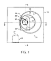
- FIG. 1 through 3 a positioning apparatus 10 mounted on the wall 16 of a chamber 15 for pouring a liquid from a vessel 20 into a container 25 with a target or aim point 27 for the liquid stream, the vessel, container and pour stream all being inside the chamber.
- FIG. 1. is a view of the positioning apparatus 10 from outside the chamber. Consequently, container 25 and vessel 20 are shown in phantom in FIG. 1.
- chamber 15 is shown as an enclosed box for convenience of depicting one type of chamber that could be used, rather than limiting the configuration of the chamber.
- Container 25 can be any type of receptacle having an opening for receiving the fluid stream.
- the receptacle may be a mold, with aim point 27 being the center of the mold's pour cup. It should be appreciated that the aim point 27 generally represents the center of a fluid stream since the stream will pass through a defined area, rather than a point.
- Vessel 20 generally has a pour lip 22 over which the fluid flows when the vessel is tilted.
- the pour lip can also be a spout or other element that provides a flow path for molten metal out of the vessel when the vessel is tilted.
- Vessel 20 may be a furnace, ladle, or other apparatus known in the art of processing molten or other liquid materials.
- First element 30 is disposed to cover an opening 31 in the wall 16 of chamber 15.
- First element 30, rotatable about a first axis of rotation 32, is mounted on wall 16 and is peripherally sealed to the wall by a circular, substantially gas-tight dynamic seal such as an elastomeric O-ring, which is substantially concentric with the first axis of rotation 32.
- first element 30 has an opening 41 to allow for the passage of vessel mounting structure 60 through first element 30.
- Second element 40 is rotatably attached and similarly peripherally sealed to first element 30, covering the opening 41 in first element 30.
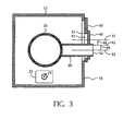
- Second element 40 is rotatable about a second axis of rotation 42, which is substantially parallel to first axis of rotation 32. As shown in the figures, second element 40 has an opening to allow for the passage of vessel mounting structure 60 through second element 40. For clarity, rotational means, bearings and seals for second circular element 40 are not shown in FIG. 1 through 3. As shown in FIG. 3, axes of rotation 32 and 42 are separated by a first offset distance 48.
- first and second elements 30 and 40 may be circular metal plates, with appropriate openings, supported by peripherally located roller, plain or other bearings.
- Vessel mounting structure 60 is a hollow tube in the shape of a circular cylinder.
- the first open base of the cylindrical mounting structure 60 defines a third element 50, as shown in the figures.
- the end of the cylindrical mounting structure 60 opposite the first open base provides a point of connection to vessel 20.
- mounting structure 60 is rotatably disposed in an opening in the second circular plate 40 and peripherally sealed to it.
- Third element 50 is rotatable about a third axis of rotation 52, which is substantially parallel to second axis of rotation 42. As shown in FIG. 3 , axes of rotation 52 and 42 are separated by second offset distance 49.
- first and second offset distances 48 and 49 are substantially equal.
- vessel mounting structure 60 is shown in the drawings as a hollow circular cylinder, other configurations are also satisfactory as long as the structure is used to mount vessel 20 so that the vessel can be rotated about the third axis of rotation 52 located as described above. Consequently, rotation of the mounting structure 60 about the third axis of rotation 52 will also result in corresponding rotation of the connected vessel 20.
- vessel 20 is in the zero degree tilt position (angle of vertical centerline of the vessel from the vertical Y-axis).
- a hollow cylinder is not a necessity, but if the vessel 20 is a furnace which requires cables and tubing to supply electrical power and cooling water, the bore of a hollow cylinder provides a convenient path for routing such cables and tubing.
- bearings, seals and rotational components for first and second elements, 30 and 40, and for vessel mounting structure 60 can be made in many ways, particular components are described below.
- first and second offset distances 48 and 49 are equal (equal offset distance)
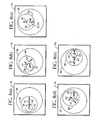
- rotation of first element 30 and second element 40 through equal angles in opposite directions about their respective axes of rotation 32 and 42 will result in a horizontal translation of the vessel as shown in FIG. 4(a) through 4(e).
- a simultaneous coordinated rotation of vessel mounting structure 60 about the third axis of rotation 52 permits the vessel to be positioned at any desired vessel tilt angle for any horizontal position.
- first and second elements 30 and 40 can be used to establish a selected pour profile of liquid over the pour lip so that the liquid stream has a desired rate of flow and its center is continually directed to the predetermined aim point 27.
- the present invention provides for an equivalent range of horizontal movement in less space.
- coordinated varying rotation of first and second elements 30 and 40 can be used to move the third axis of rotation 52 along a trajectory that lies anywhere within a circle 68 shown in phantom in Fig.1.
- Circle 68 is concentric with first element 30 and has a diameter equal to four times the equal offset distance.
- Selection of a trajectory having appropriate vertical, horizontal and vessel tilt components can provide uncoupled, independent control of not only the pour rate and fluid stream aiming, but also the height of the vessel's lip above the aim point.
- the availability of independent vertical, horizontal and tilting motions can also be useful for other purposes, such as positioning the vessel for filling or maintenance.
- first, second and third elements, 30,40 and 50 (and the vessel 20 and mounting structure 60 by connection to third element 50) is used to indicate angular position of the rotating components, as they move through their complete range of horizontal motion.
- the vessel remains at zero tilt angle throughout this sequence; though it should be appreciated that, at any horizontal location, third element 50 and connected mounting structure 60 may be rotated to tilt the connected vessel, and to thereby obtain a liquid pour stream with a desired flow rate.
- first element 30 is peripherally connected to a fixed supporting structure, which can be the wall 16 of a chamber 15.
- the peripheral connection between the first element 30 and the fixed supporting structure is such that the first element 30 can be rotated about its axis of rotation 32.
- Second element 40 is peripherally connected to the first element 30 in a manner such that the second element 40 can rotate about its axis of rotation 42.
- the second axis of rotation 42 is located within the periphery of the first element 30.
- Third axis of rotation 52 is locate within the periphery of the second element 40.
- vessel supporting structure 60 is a structure projecting from the perimeter of the third element 50. The supporting structure passes through openings in the first and second elements.
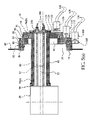
- Fig. 5(a) shows in cross sectional view one preferred arrangement of the bearings, seals and drive means of the present invention.
- first element 30 has been rotated 90 degrees clockwise from the position shown in FIG. 1 through 3.
- vessel mounting structure 60 has been rotated 90 degrees counter clockwise, to keep the vessel at zero tilt angle.
- Fig. 5(a) thereby illustrates the vessel at maximum translation in the upwards, or Y direction.
- the chamber has a circular opening in its wall 16 that is bounded by a chamber structural supporting ring 17.
- Chamber structural supporting ring 17 is integrally connected to the wall of the chamber.
- Adapter ring 82 is connected to chamber structural supporting ring 17.
- the interface for the adapter ring and chamber structural supporting ring is environmentally sealed by static O-ring 84.
- the chamber structural supporting ring 17 and adapter ring 82 can be integral with the wall 16 of the chamber.
- Adapter ring 82 supports first peripheral ball bearing assembly 88, which provides the rotational support for first element 30.
- First element 30 is connected to and supported by ball bearing assembly 88 as shown in FIG. 5(a).
- O-ring seals 86 are located concentric with ball bearing assembly 88 in adjacent grooves in first element 30 as shown in detail in FIG. 5(b).
- One or more O-rings can be provided. The preferred embodiment with two O-ring seals 86 is shown in the figures.
- the space between the two O-rings is preferably filled with an oil or grease to provide lubrication for these O-rings, which dynamically seal first element 30 to the adjacent surface of adapter ring 82.
- Ball bearing assembly 88 has radially-oriented gear teeth 89 disposed around its outer periphery.
- First pinion gear 102 driven by first hydraulic motor 100, engages teeth 89.
- Motor 100 is attached by conventional mounting means not shown in the drawings to the wall 16 of the chamber 15. This arrangement allows motor 100 to rotate first element 30 relative to wall 16.
- first element 30 supports ball bearing assembly 90, which provides the rotational means for second element 40.
- Second element 40 is connected to and supported by ball bearing assembly 90 as best shown in FIG. 5(b).
- 0-ring seals 92 are located concentric with ball bearing assembly 90 in adjacent groves in second element 40 as shown in detail in FIG. 5(b).
- One or more O-rings can be provided.
- the preferred embodiment with two O-ring seals 92 is shown in the figures.
- the space between the two O-rings is preferably filled with an oil or grease to provide lubrication for these O-rings, which dynamically seal second element 40 to the adjacent surface of first element 30.
- Ball bearing assembly 90 has radially-oriented gear teeth 91 disposed around its outer periphery.
- Second pinion gear 112 driven by second hydraulic motor 110, engages teeth 91.
- Motor 110 is attached by conventional mounting means not shown in the drawings to first element 30. This arrangement allows motor 110 to rotate second element 40 relative to first element 30.
- vessel mounting structure 60 is supported from a tubular extension 45 of second element 40 by dual co-axial ball bearing assemblies 96a and 96b.
- Dynamic sealing of vessel mounting structure 60 to second element 40 is by dual lubricated O-ring seals 94 between the tubular extension 45 of second element 40 and the vessel supporting structure as best shown in FIG. 5(c).
- One or more O-ring seals can be provided.
- third element 50 is defined as the first open base of the cylindrical vessel mounting structure 60 adjacent to ball bearing assembly 96(b) .
- Rotation of vessel mounting structure 60 relative to second element 40 is performed by a sprocket drive.
- Third hydraulic motor 120 has first sprocket 122 attached to its output shaft.
- Second sprocket 126 is radially attached to the exterior of the first base of vessel mounting structure 60.
- the links of chain 124 are engaged by sprockets 122 and 126 to rotate vessel mounting structure 60.
- Motor 120 is attached by conventional mounting means not shown in the drawings to second element 40.
- first and second elements 30 and 40 are circular plates with openings and fastener means for connection to components in the positioning system 10.
- Circular packing elements 270 provide closure for the open base of the vessel mounting structure and transit openings for cables 280 that transport electrical power and cooling water to vessel 20.
- hydraulic fluid supply and return lines 128 connect motors 100, 110 and 120 to a hydraulic power and control system further described below.
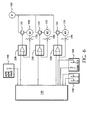
- a preferred method for controlling the rotational positions of the first and second elements 30 and 40 and vessel mounting structure 60 of the present invention is shown schematically in Fig. 6 .
- Hydraulic fluid from a pressurized source 160 such as a hydraulic pump, flows to first hydraulic motor 100, which is bi-directional, via first four-way hydraulic valve 130.
- the flow of hydraulic fluid through valve 130 is controlled by the output signal from first position error amplifier 200.
- This error amplifier receives a position command signal from a system controller 230, and a position feedback signal from first potentiometer 170, which indicates the angular position of first element 30 relative to the wall 16 of chamber 15.
- the wiper arm of potentiometer 170 is connected to first element 30 and the potentiometer's resistive element is attached to the wall of chamber in suitable fashion so that angular rotation of first element 30 will result in a change of the potentiometer's resistance that will be proportional to the degree of angular rotation of first element 30.
- Error amplifier 200 is designed such that any difference between the desired position of first element 30, represented by a command signal from system controller 230, and the actual angular position of first element 30, represented by the signal from potentiometer 170, causes an output signal to be produced. This signal causes valve 130 to open such that the resulting flow of oil from pressurized source 160 to motor 100 causes motor 100 to rotate.
- Motor 100 mounted on chamber 15 and having an output shaft that is rotationally coupled to first element 30, causes first element 30 and the wiper of potentiometer 170 to rotate in a direction which reduces the above difference.
- valve 130 closes and motor 100 stops.
- First element 30 is therefore continuously driven by this hydraulic position control loop to the angular position commanded by system controller 230.
- valve 130 is preferably a servo or proportioning type valve in which the opening of the valve is proportional to the signal received from position error amplifier 200.
- System controller 230 preferably comprises a digital storage and computing device, capable of storing a series of values for the desired position of first element 30 and outputting these as command signals in a timed sequence during a pour or other vessel motion.
- the rotational position of second element 40 relative to first element 30, as indicated by second potentiometer 180 is controlled at a second angular position commanded by system controller 230 by a second hydraulic position control loop that includes second four-way hydraulic valve 140, second position error amplifier 210 and second (bi-directional) hydraulic motor 110.
- the rotational position of vessel mounting structure 60 relative to second element 40 is controlled at a third angular position commanded by system controller 230 by a third hydraulic position control loop that includes third four-way hydraulic valve 150, third position error amplifier 220 and third (bi-directional) hydraulic motor 120.
- potentiometers used in the preferred embodiment are one type of angular position transducer sensors known in the art. Other position sensors are readily adaptable to the present invention.
- the four-way hydraulic valves 130,140 and 150 will be understood to be drive controllers for controlling the speed and direction of the position outputs of the appropriate rotational means that replace the hydraulic motors 100, 110, and 120.
- System controller 230 is preferably a digital computer, programmable logic controller or 3-axis digital motion controller.
- Error amplifiers 200, 210 and 220 may advantageously be of the Proportional Integral Derivative (PID) type well known to those skilled in the closed-loop-position-control art.
- PID Proportional Integral Derivative
- Commercially available digital motion controllers often include such amplifiers, implemented partially in software.
- system controller 230 is preferably also programmed with an algorithm that converts any desired position of the vessel, expressed in the form of X and Y coordinates, or components in another coordinate system, plus the vessel's tilt angle relative to the wall 16 of chamber 15, into the corresponding rotational angles of first, second and third elements, 30, 40 and 50 (and vessel mounting structure 60 by connection to element 50).
- system controller 230 continuously maintains master position values for the desired X and Y coordinates of the vessel, together with its tilt angle.
- the algorithm described above converts these values to corresponding rotational position commands for the three hydraulic positioning loops, as previously described.
- system controller 230 converts a stored sequence of X, Y and tilt angle positions into a corresponding series of rotational position commands for the three hydraulic position control loops. If the vessel motion is for an automated pour, this causes rotational motion about the three axes such that the pour rate of the fluid from the vessel follows a desired flow rate profile, the position of the terminal end of the pour stream is maintained at the aim point 27 and, optionally, the vertical position of the pour lip of the vessel relative to the aim point is also controlled.
- One way to generate the required list of master positions is by a process in which a skilled operator makes a manually controlled vessel movement and the system controller 230 records the resulting master positions at frequent intervals as the vessel motion proceeds.
- the preferred control system includes joysticks 250 and 260.
- Other types of input devices are also suitable.
- Joystick 250 has a spring-centered handle movable in two directions, X and Y. The displacement of joystick 250 in each direction produces a proportional output signal on a corresponding potentiometer. Signals from these potentiometers are read by system controller 230 as representing a desired velocity of vessel 20 in the corresponding X and Y directions.
- joystick 250 is preferably mounted such that movement of the joystick handle in a particular direction results in vessel motion in the same direction, be it X, Y or any combination of the two.
- joystick 260 is similar to 250 but has a single potentiometer representing the desired tilt velocity.
- Operation of the system in the manual control mode is as follows. Manual displacement of any joystick handle away from its spring-centered position causes system controller 230 to increment or decrement the corresponding master position value, i.e., X-position, Y-position, tilt angle or any combination of these three values. The rate at which each of the master values is changed is made proportional to the corresponding joystick handle displacement. At frequent intervals, the newly calculated master position values are converted to position values for each of the three hydraulic positioning loops by the algorithm previously mentioned, and outputted as position commands. The hydraulic servo positioning loops cause the vessel 20 to move as directed by system controller 230. New loop position commands are preferably generated by system controller 230 sufficiently frequently that the resulting vessel motion takes place smoothly.
- any manually controlled movement operation may be recorded.
- pushbutton activation causes the ensuing sequence of master position commands to be stored by system controller 230 as a profile that may be re-called and re-played at any later time.
- System controller 230 is preferably able to store a number of such profiles.
- the operator Prior to activating such a pre-recorded movement, the operator would indicate to system controller 230, by means of a keyboard or other input device not shown in Fig 6 , which of the pre-stored motion profiles is to be used.
- the corresponding vessel motion would thereafter commence upon a command, such as activation of pushbutton 240.
- Such a pre-recorded vessel motion may be used to perform a pour operation, or to achieve any other vessel re-positioning that may be repetitively required during the course of operation or maintenance.
- the list of mastervessel positions required for a motion profile may also be obtained by pre-calculation from the geometry and dynamics of the system. Such calculations may be performed by system controller 230, or by another computing device, the resulting sequence of master vessel positions being communicated to system controller 230.
- a pour profile comprising a manually or automatically generated motion profile resulting from rotational movements of the first and second elements 30 and 40, either separately or coordinately, and a manually or automatically generated rotation of the third element 50, with attached vessel 20 and supporting structure 60, can be executed to pour liquid from the vessel to a predetermined location or aim point 27.
- the pouring apparatus and process disclosed in the present invention is particularly applicable to technologies using chambers that operate under internal vacuum or internal positive pressure. It may also be used for applications that use a controlled atmosphere at ambient atmospheric pressure. Furthermore, two synchronously driven sets of the mechanical parts of the apparatus disclosed in the present invention, can be located on opposite sides of a large vessel to provide two-sided support for such a vessel.
Landscapes
- Engineering & Computer Science (AREA)
- Mechanical Engineering (AREA)
- Devices For Dispensing Beverages (AREA)
- Control Of Position Or Direction (AREA)
- Loading And Unloading Of Fuel Tanks Or Ships (AREA)
- Feeding, Discharge, Calcimining, Fusing, And Gas-Generation Devices (AREA)
Applications Claiming Priority (3)
| Application Number | Priority Date | Filing Date | Title |
|---|---|---|---|
| US337058 | 1999-06-21 | ||
| US09/337,058 US6168053B1 (en) | 1999-06-21 | 1999-06-21 | Positioning apparatus and method for precision pouring of a liquid from a vessel |
| PCT/US2000/016071 WO2000078481A1 (en) | 1999-06-21 | 2000-06-12 | Positioning apparatus and method for precision pouring of a liquid from a vessel |
Publications (3)
| Publication Number | Publication Date |
|---|---|
| EP1109639A1 EP1109639A1 (en) | 2001-06-27 |
| EP1109639A4 EP1109639A4 (en) | 2005-03-16 |
| EP1109639B1 true EP1109639B1 (en) | 2007-01-03 |
Family
ID=23318940
Family Applications (1)
| Application Number | Title | Priority Date | Filing Date |
|---|---|---|---|
| EP00944645A Expired - Lifetime EP1109639B1 (en) | 1999-06-21 | 2000-06-12 | Positioning apparatus and method for precision pouring of a liquid from a vessel |
Country Status (7)
| Country | Link |
|---|---|
| US (1) | US6168053B1 (https=) |
| EP (1) | EP1109639B1 (https=) |
| JP (1) | JP2003502228A (https=) |
| AU (1) | AU5871100A (https=) |
| CA (1) | CA2341252C (https=) |
| DE (1) | DE60032719T2 (https=) |
| WO (1) | WO2000078481A1 (https=) |
Families Citing this family (4)
| Publication number | Priority date | Publication date | Assignee | Title |
|---|---|---|---|---|
| DE10065401A1 (de) * | 2000-12-27 | 2003-03-06 | Siemens Ag | Automatisierungssystem |
| US20070272012A1 (en) * | 2006-05-25 | 2007-11-29 | Subnick Howard D | Portable Liquid Gauge |
| US7469584B1 (en) | 2007-08-10 | 2008-12-30 | Subnick Howard D | Adjustable liquid gauge |
| CN109986065A (zh) * | 2019-04-28 | 2019-07-09 | 莱州市电子仪器有限公司 | 可控制倾倒流速的装置 |
Family Cites Families (13)
| Publication number | Priority date | Publication date | Assignee | Title |
|---|---|---|---|---|
| GB590202A (en) * | 1945-01-05 | 1947-07-10 | Edward Spurr | Improvements in or relating to compound eccentric mountings |
| US2892225A (en) | 1954-06-23 | 1959-06-30 | Buhrer Erwin | Process and means for casting system for operating pouring ladles |
| GB809683A (en) * | 1956-04-10 | 1959-03-04 | Peter Dunsforth Matterson | Improvements in mountings for shafts, axles and other elements |
| US3856183A (en) | 1974-03-25 | 1974-12-24 | Nl Industries Inc | Tilting molten metal dispenser with constant liquid head control |
| DE3532763A1 (de) * | 1984-09-15 | 1986-03-27 | Gebr. Wöhr GmbH und Co KG, 7080 Aalen | Verfahren und vorrichtung zum automatischen vergiessen von fluessigem metall |
| DE3524858A1 (de) | 1985-07-12 | 1987-01-22 | Leybold Heraeus Gmbh & Co Kg | Anordnung fuer die steuerung des kippvorgangs eines schmelztiegels |
| JPH0625933B2 (ja) * | 1986-10-02 | 1994-04-06 | 科学技術庁航空宇宙技術研究所長 | 複合偏心型回転子による電動直接駆動位置決め装置 |
| JPH0653354B2 (ja) * | 1987-11-11 | 1994-07-20 | 科学技術庁航空宇宙技術研究所長 | 複合偏心型回転体による電動直接駆動位置決め装置 |
| FR2631266B1 (fr) * | 1988-05-13 | 1990-09-14 | Detalle Edouard | Obturateur de coulee a deplacement lineaire et symetrie axiale |
| JPH04367367A (ja) * | 1991-06-11 | 1992-12-18 | Nkk Corp | ロータリノズル |
| DE59307156D1 (de) | 1992-10-07 | 1997-09-25 | Mezger Ag Maschf Giesserei | Verfahren und Vorrichtung zur Bewegungssteuerung einer Giesspfanne in einer Giessanlage |
| DE19500012A1 (de) * | 1995-01-02 | 1996-07-04 | Didier Werke Ag | Regel- und Verschlußeinrichtung für ein metallurgisches Gefäß |
| US5792378A (en) | 1996-08-02 | 1998-08-11 | Lockheed Martin Advanced Environmental Systems, Inc. | Method and apparatus for controlling the flow rate and aiming when pouring molten material from a container |
-
1999
- 1999-06-21 US US09/337,058 patent/US6168053B1/en not_active Expired - Lifetime
-
2000
- 2000-06-12 EP EP00944645A patent/EP1109639B1/en not_active Expired - Lifetime
- 2000-06-12 JP JP2001504529A patent/JP2003502228A/ja active Pending
- 2000-06-12 AU AU58711/00A patent/AU5871100A/en not_active Abandoned
- 2000-06-12 CA CA002341252A patent/CA2341252C/en not_active Expired - Fee Related
- 2000-06-12 DE DE60032719T patent/DE60032719T2/de not_active Expired - Lifetime
- 2000-06-12 WO PCT/US2000/016071 patent/WO2000078481A1/en not_active Ceased
Also Published As
| Publication number | Publication date |
|---|---|
| DE60032719T2 (de) | 2007-05-16 |
| WO2000078481B1 (en) | 2001-03-08 |
| CA2341252C (en) | 2009-09-15 |
| DE60032719D1 (de) | 2007-02-15 |
| AU5871100A (en) | 2001-01-09 |
| EP1109639A1 (en) | 2001-06-27 |
| US6168053B1 (en) | 2001-01-02 |
| EP1109639A4 (en) | 2005-03-16 |
| CA2341252A1 (en) | 2000-12-28 |
| JP2003502228A (ja) | 2003-01-21 |
| WO2000078481A1 (en) | 2000-12-28 |
Similar Documents
| Publication | Publication Date | Title |
|---|---|---|
| EP0066393B1 (en) | Multiarm robot | |
| US4300198A (en) | Robot with light-weight, inertia-free programming device | |
| US4595334A (en) | Robotic apparatus with improved positioning accuracy | |
| US4543033A (en) | Industrial robot | |
| EP0418388A1 (en) | Horizontal articulated robot | |
| EP1109639B1 (en) | Positioning apparatus and method for precision pouring of a liquid from a vessel | |
| US4030615A (en) | Manipulator for movement of articles in a controlled environment chamber, especially a high vacuum chamber | |
| JPS60255381A (ja) | マニピユレータ装置 | |
| KR20200000356A (ko) | 기판 배치대 및 성막 장치 | |
| EP0019596B1 (en) | Robot with light-weight, inertia-free programming device | |
| KR100382847B1 (ko) | 유체 처리 장치 | |
| EP1019885B1 (en) | Motion-imparting apparatus | |
| US5792378A (en) | Method and apparatus for controlling the flow rate and aiming when pouring molten material from a container | |
| FR2825445A1 (fr) | Procede d'orientation d'une tourelle hexapode | |
| JP4393583B2 (ja) | 溶融物質を注ぐ方法および装置 | |
| CN120228379B (zh) | 一种建筑自动化电弧焊机器人手臂 | |
| US4820900A (en) | Vacuum plasma spray system with sealed manipulator | |
| US4085952A (en) | Flexible stem valve | |
| US4781520A (en) | Polar-coordinate manipulator for vacuum application | |
| US4901627A (en) | Hydraulic idling-regulating valve | |
| US4177644A (en) | Apparatus for controlling and taking up axial displacement in machinings on large diameter cylinders | |
| CN222332136U (zh) | 用于分子束外延及晶体生长的装置 | |
| JP3232400U (ja) | 粉粒体処理装置 | |
| JPH0756078B2 (ja) | 固体の厚さプロフィルを変更するためのプログラムされたプラズマエッチング装置の運動装置 | |
| JPH0333037Y2 (https=) |
Legal Events
| Date | Code | Title | Description |
|---|---|---|---|
| PUAI | Public reference made under article 153(3) epc to a published international application that has entered the european phase |
Free format text: ORIGINAL CODE: 0009012 |
|
| 17P | Request for examination filed |
Effective date: 20010221 |
|
| AK | Designated contracting states |
Kind code of ref document: A1 Designated state(s): AT BE CH CY DE DK ES FI FR GB GR IE IT LI LU MC NL PT SE |
|
| AX | Request for extension of the european patent |
Free format text: AL;LT;LV;MK;RO;SI |
|
| RBV | Designated contracting states (corrected) |
Designated state(s): DE FR GB |
|
| A4 | Supplementary search report drawn up and despatched |
Effective date: 20050128 |
|
| RIC1 | Information provided on ipc code assigned before grant |
Ipc: 7B 65B 1/04 B Ipc: 7C 21C 5/42 B Ipc: 7B 65B 3/04 B Ipc: 7F 27B 14/08 B Ipc: 7F 27D 3/14 B Ipc: 7B 22D 37/00 A Ipc: 7F 27B 14/02 B |
|
| 17Q | First examination report despatched |
Effective date: 20050422 |
|
| GRAP | Despatch of communication of intention to grant a patent |
Free format text: ORIGINAL CODE: EPIDOSNIGR1 |
|
| GRAS | Grant fee paid |
Free format text: ORIGINAL CODE: EPIDOSNIGR3 |
|
| GRAA | (expected) grant |
Free format text: ORIGINAL CODE: 0009210 |
|
| AK | Designated contracting states |
Kind code of ref document: B1 Designated state(s): DE FR GB |
|
| REG | Reference to a national code |
Ref country code: GB Ref legal event code: FG4D |
|
| REF | Corresponds to: |
Ref document number: 60032719 Country of ref document: DE Date of ref document: 20070215 Kind code of ref document: P |
|
| ET | Fr: translation filed | ||
| PLBE | No opposition filed within time limit |
Free format text: ORIGINAL CODE: 0009261 |
|
| STAA | Information on the status of an ep patent application or granted ep patent |
Free format text: STATUS: NO OPPOSITION FILED WITHIN TIME LIMIT |
|
| 26N | No opposition filed |
Effective date: 20071005 |
|
| REG | Reference to a national code |
Ref country code: FR Ref legal event code: PLFP Year of fee payment: 16 |
|
| PGFP | Annual fee paid to national office [announced via postgrant information from national office to epo] |
Ref country code: GB Payment date: 20150610 Year of fee payment: 16 Ref country code: DE Payment date: 20150609 Year of fee payment: 16 |
|
| PGFP | Annual fee paid to national office [announced via postgrant information from national office to epo] |
Ref country code: FR Payment date: 20150608 Year of fee payment: 16 |
|
| REG | Reference to a national code |
Ref country code: DE Ref legal event code: R119 Ref document number: 60032719 Country of ref document: DE |
|
| GBPC | Gb: european patent ceased through non-payment of renewal fee |
Effective date: 20160612 |
|
| REG | Reference to a national code |
Ref country code: FR Ref legal event code: ST Effective date: 20170228 |
|
| PG25 | Lapsed in a contracting state [announced via postgrant information from national office to epo] |
Ref country code: FR Free format text: LAPSE BECAUSE OF NON-PAYMENT OF DUE FEES Effective date: 20160630 Ref country code: DE Free format text: LAPSE BECAUSE OF NON-PAYMENT OF DUE FEES Effective date: 20170103 |
|
| PG25 | Lapsed in a contracting state [announced via postgrant information from national office to epo] |
Ref country code: GB Free format text: LAPSE BECAUSE OF NON-PAYMENT OF DUE FEES Effective date: 20160612 |